2. The OSI Model and the TCP/IP Protocol Suite
The layered model that dominated data communication and networking literature before 1990 was the Open Systems Interconnection (OSI) model. Everyone believed that the OSI model would became the ultimate standard for data communications-- but this did not happen. The TCP/IP Protocol suite became the dominant commercial architecture, because it was used and tested extensively in the Internet; the OSI model was never fully implemented.
In this chapter, we first briefly discuss the OSI model and then we concentrate on TCP/IP as a protocol suite.
OBJECTIVES
The chapter has several objectives:
- To discuss the idea of multiple layering in data communication and networking and interrelationship between layers.
- To discuss and the OSI model and its layer architecture and to show the interface between the layers.
- To briefly discuss the functions of each layer in the OSI model.
- To introduce the TCP/IP protocol suite and compare its layers with the ones in the OSI model.
- To show the functionality of each layer in the TCP/IP protocol with some example.
- To discuss the addressing mechanism used in some layers of the TCP/IP protocol suite for the delivery of a message from the source to destination.
2.1 Protocol Layers
In Chapter 1, we discussed that a protocol is required when two entities need to communicate. When communication is not simple, we may divide the complex task of communication into several layers. In this case, we may several protocols, one for each layer.
Let us use a scenario in communication in which the role of protocol layering may be better understood. We use two examples. In the first example, communication is so simple that it can occur in only one layer. In the second example, we need three layers.
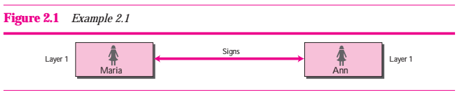
Example 2.1
Assume Maria and Ann are neighbors with a lot of common ideas. However, Maria speeks only Spanish, and Ann speeks only English. Since both have learned the sign language in their childhood, they enjoy meeting in a cafe a couple of days per week and exchange their ideas using signs. Occasionally, they also use a bilingual dictionary. Communication is face to face and happens in one layer as shown in Figure 2.1.
Example 2.2
Now assume that Ann has to move to another town because of her job. Before she moves, the two meet for the last time in the same cafe. Although both are sad, Maria surprises Ann when she open a packet that contains two samll machines. The first machine can scan and transform a letter in English to a secret code or vice versa. The other machine can scan and translate a letter in Spanish to the same code or vice versa. Ann takes the first machine; ,Maria keeps the second one. The two friends can still communicate using the secret code, as shown in Figure 2.2.
Communication between Maria and Ann happens as follows. At the third layer, Maria writes a letter in spanish, the language she is comfortable with. She then uses the translator machine that scans the letter and creates a letter in the secret code. Maria then puts the letter in an envelop and drops it to the post office box. The letter is carried by the post office truck to the post office of the city where Ann lives now. In the post office, the letter is delivered to the Ann residence. Ann uses her own machine to change the secret code to a letter in the English. The communication from Ann to Maria uses the same process, but in the reverse direction. The communication in both directions is carried in the secret code, a language that neither Maria nor Ann understands, but through the layered communication, they can exchange ideas.
Figure 2.2 Example 2.2
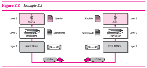
Hierarchy
Using Example 2.2, there are three different activities at the sender site and another three activities at the receiver site. The task of transporting the letter between the sender and the receiver is done by the carrier. Something that is not obvious immediately is that the tasks must be done in the order given in the hierarchy. At the sender site, the letter must be written, translated to secret code, and dropped in the mailbox before being picked up by the letter carrier and delivered to the post office. At the receiver site, the letter must be dropped in the recipient mailbox before being picked up and read by the recipient.
Services
Each layer at the sending site uses the services of the layer immediately below it. The sender at the layer uses the services of the middle layer. The middle layer uses the services of the lower layer. The lower laye uses the services of the carriers.
2.2 The OSI Model
Established in 1947, the International Standards Organization(ISO) is a multinational body dedicated to worldwide agreement on international standards. Almost three-fourths of countries in the world are represented in the ISO. An ISO standard that covers all aspects of network communications is the Open Systems Interconnection (OSI) model. It was first introduced in the late 1970s.
ISO is the organization; OSI is the model.
An open system is a set of protocols that allows any two different systems to communication regardless of their underlying architecture. The purpose of the OSI model is to show to facilitate communication between different systems without requiring changes to the logic of the underlying hardware and software. The OSI model is not a protocol; it is a model forunderstanding and designing a network architecture that is flexible, robust, and interoperable. The OSI model was intended to be the basis for the creation of the protocols in the OSI stack.
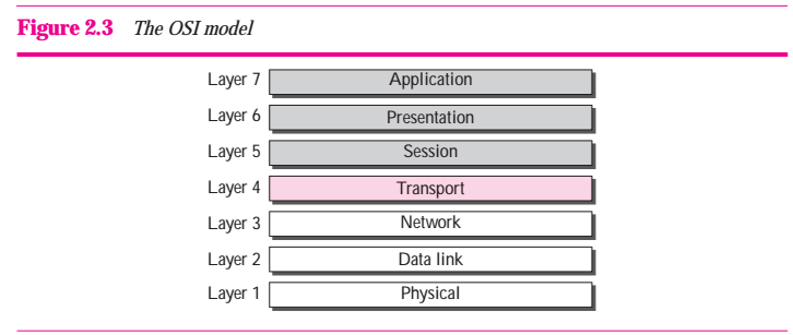
The OSI model is a layered framework for the design of network systems that allows communication between all types of computer systems. It consists of seven separate but related layers, each of which defines a part of the process of moving information provides a solid basis for exploring data communications.
Figure 2.3 The OSI model
Layered Architecture
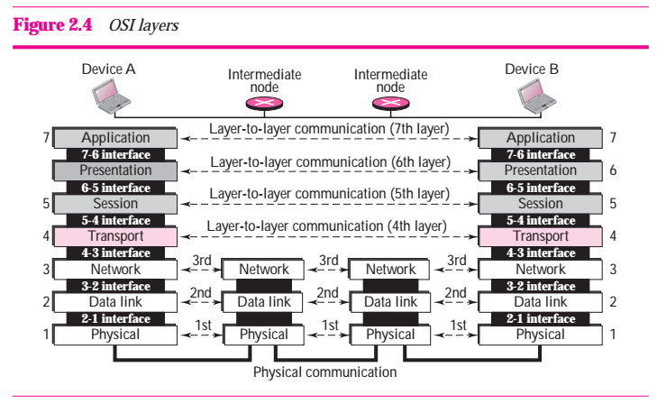
The OSI model is composed of seven ordered layers: physical (layer 1), data link (layer 2), network(layer 3), transport (layer 4), session (layer 5), presentation (layer 6), and application (layer7). Figure 2.4 shows the layers involved when a message is sent from device A to device B. As the message travels from A to B, it may pass through many intermediate nodes. These intermediate nodes usually involve only the first three layers of the OSI model.
In developing the model, the designers distilled the process of transmitting data to its most fundamental elements. They identified which networking functions had related uses and collected those functions into discrete groups that because the layers. Each layer defines a family of functions distinct from those of the other layers. By defining and localizing functionality in this fashion, the designers created an architecture that is both comprehensive and flexible. Most important, the OSI model allows complete interoperability between otherwise incompatible systems.
Within a single machine, each layer calls upon the services of the layer just below it. Layer 3, for example, uses the services provided by layer 2 and provides services for layer 4. Between machines, layer x on one machine logically communicates with layer x on another machine. This communication is governed by an agreed-upon series of rules and conventions called protocols.
Layer-to-layer Communication
In Figure 2.4, device A sends a message to device B (through intermediate nodes). At the sending site, the message is moved down layer 7 to layer 1 . At layer 1 the entrie package is converted to a form that can be transferred to the receiving site. At the receiving site, the message is moved up from layer1 to layer 7.
Interfaces between Layers
The passing of the data and network information down through the layers of the sending device and back up through the layers of the receiving device is made possible by an interface between each pair of adjacent layers. Each interface defines what information and services a layer must provide for the layer above it. Well-defined interfaces and layer functions provide modularity to a network. As long as a layer provides the expected services to the layer above it, the specific implementation of its functions can be modified or replaced without requiring changes to the surrounding layers.
Organization of the Layers
The seven layers can be thought of as belonging to three subgroups. Layers 1, 2, and 3 --physical, data link, and network-- are the network support layer; they deal with the physical aspects of moving data from one device to another (such as electrical specifications, physical connections, physical addressing, and transport timing and reliability). Layers 5 , 6, and 7 --- seesion, presentation, and application-- can be throught of as the user support layers; they allow interoperability among unrelated software systems. Layer 4 , the transport layer, links the two subgroups and ensures that what the lower layers have transmitted is in a form that the upper layers can use. The upper OSI layers are almost always implemented in software; lower layers are a combination of hardware and software, expect for the physical layer, which is mostly hardware.
In Figure 2.5, which gives an overall view of the OSI layers, D7 data means the data unit at layer 7, D6 data means the data unit at layer 6, and so on. The process starts at layer 7 (the application layer), then moves from layer to layerin descending, sequential order. At each other, a header can be added to the data unit. At layer 2, a trailer may also be added. When the formatted data unit passes through the physical layer (layer 1), it is changed into an electromagnetic signal and transported along a physical link.
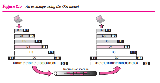
Upon reaching its destination, the signal passes into layer 1 and is transformed back into digital form. The data units then move back up through the OSI layers. As each block of data reaches the next higher layer, the headers and trailers atteched to it at the corresponding sending layer are removed, and actions appropriate to that layer are taken. By the time it reaches layer 7, the message is again in a form appropriate to the application and is made available to the recipient.
Encapsulation
Figure 2.5 reveals another aspect of data communication in the OSI model: encapsulation. A packet at level 7 is encapsulated in the packet at the level 6. The whole packet at level 6 is encapsulated in a packet at level 5, and so on.
In other words, the data part of a packet at level N is carrying the whole packet (data and overhead) from level N+1. The concept is called encapsulation because level N is not aware what part of the encapsulated packet is data and what part is the header or trailer. For level N, the whole packet coming from N+1 is treated as one integral unit.
Layers in the OSI Model
In this section we briefly describe the functions of each layer in the OSI model.
Physical Layer
The physical layer coordinates the functions to carry a bit stream over a physical medium. It also define the procedures and funcations that physical devices and interfaces have to perform for transmission to occur.
The physical layer is responsible for moving individual bits from one (node) to the next.
The physical layer is also concerned with the following.
- Physical characteristic interfaces and media. The physical layer defines the characteristics of the interface between the devices and the transmission media. It also defines the type of transmission media (See Chapter 3).
- Representation of bits. The physical layer data consists of a stream of bits (sequence of 0s and 1s) with no interpretation. To be transmitted. To be transmitted, bits must be encoded into singals -- electrical or optical. The physical layer defines the type of encoding ( how 0s and 1s are changed to signals).
- Data rate. The transmission rate-- the number of bits sent each second-- is also defined by the physical layer. In other words, the physical layer defines the duration of a bit, which is how long it lasts.
- Synchronization of bis. The sender and receiver must be only use the same bit rate but also be synchronized at the bit level. In other words, the sender and the receiver clocks must be synchronized.
- Line configuration. The physical layer is concerned with the connection of devices to the media. In a point-to-point configuration, two devices are connected together through a dedicated link. In a multipiont configuration, a link is shared between several devices.
- Physical topology. The physical topology defines how devices are connected to make a netwrok. Devices can be connected using a mesh topology (every device connected to every other device), a star topology (devices are connected through a central device), a ring topology (each device is connected to the next, forming a ring), or a bus topology (every device on a common link)
- Transmission mode. The physical layer also defines the direction of transmission between two devices: simplex, half-duplex, or full-duplex. In the simplex mode, only one between can send; the other can only receive. The simplex mode is a one-way communication. In the half-duplex mode, two devices can send and receive, but not at the same time. In a full-duplex (or simply duplex) mode, two devices can send and receive at the same time.
Data Link layer
The data link layer transforms the physical layer, a raw transmission facility, to a reliable link. It makes the physical layer appear error-free to the upper layer (network layer). Other responsibilities of the data link layer include the following:
- Framing. The data link layer divides the stream of bits received from the network layer into manageable data units called frames.
- Physical addressing. If frames are to be distributed to different systems on the network, the data link layer adds a header to the frame to define the sender and /or receiver of the frame. If the frame is intended for a system outside the sender's network, the receiver address is the address is the address of the connecting device that connects the network to the next one.
- Flow control. If the rate at which the data is absorbed by the receiver is less than the rate produced at the sender, the data link layer imposes a flow control mechanism to prevent overwheling receiver.
- Error control. The data link layer adds reliability to the physical layer by adding mechanisms to detect and retransmit damaged or lost frames. It also uses a mechanism to recognize duplicate frames. Error control is normally achieved through a trailer added to the end of the frame.
- Access control. When two or more devices are connected to the same link, data link layer protocols are necessary to determine which device has control over the link at any given time.
Network play
The network layer is responsible for the source-to-destination delivery of a packet, possibly acroee multiple networks (links). Whereas the data link layer oversees the delivery of the packet between two systems on the same network (link), the network layer ensures that each packet gets from its point of origin to its final destination.
If two systems are connected to the same link, there is usually no need for a network layer. However, if the two systems are attached to different network (links) with connecting devices between the networks (links), there is often a need for the network layer to accomplish source-to-destination delivery. Other responsibilities of network layer include the following:
- Logical addressing. The physical addressing implemented by the data link layer handles the addressing problem locally. If a packet passes the network boundary, we need another addressing system to help distinguish the source and destination systems.The network layer adds a header to the packet coming from the upper layer that, among other things, includes the logical addresses of the sender and receiver.
- Routing. When independent networks or links are connected togther to create interworks (network of network) or a large ntwork, the connecting devices (called routes or switches) route or switch the packets to their final destination. One of the functions of the network layer is to provide this mechanism.
Transport Layer
The transport layer is responsible for process-to-process delivery of the entire message. A process is an application program running on the host. Whereas the network layer oversees source-to-destination delivery of individual packets, it does not recognize any relationship between those packets. It treats each one independently, as though each piece belonged to a separate message. Whether or not it does. The transport layer, on the other hand, ensures that the whole message arrives intact and in order, overseeing both error control and flow control at the source-to-destination level. Other responsibilities of the transport layer include the following:
- Service-point addressing. Computers often runn several programs at the same time. For this reason, source-to-destination delivery means delivery not only from one computer to the next but also from a specific process (running program) on one computer to a specific process (running program) on the other. The transport layer header must therefore include a type of address called a service-point address (or port address). The network layer gets each packet to the correct computer; the transport layer gets the entire message to the correct process on that computer.
- Segmentation and reassembly. A message is divided into transmittable segments, with each segment containning a sequence number. These numbers enable the transport layer to reassemble the message correctly upon arriving at the destination and to identify and replace packets that were lost in transmission.
- Connection control. The transport layer can be either connectionless or connection-oriented. A connectionless transport layer treats each segment as an independent packet and delivers it to the transport layer at the destination machine. A connection-oriented transport layer makes a connection with the transport layer at the destination machine first before delivering the packets. After all the data are transferred, the connection is terminated.
- Flow control. Like the data link layer, the transport layer is reponsible for error control. However, error control at this layer is performed process-to-process rather than across a single link. The sending transport layer makes sure that the entire message arrives at the receiving transport layer with error (damage, loss, or duplication). Error correction is usually achieved through retansmission.
Session layer
The service provided by the first four layers (physical, data link, network and transport) are not sufficient for some processes. The session layer is the network dialog controller. It establishes, maintains, and synchronizes the interaction between communicating systems. Specific responsibilities of the session layer include the following:
- Dialog control. The session layer allows two systems to enter into a dialog. It allows the communication between two processes to take place in either half-duplex (one way at one time) or full-duplex (two ways at a time) mode.
- Synchronization. The session layer allows a process to add checkpoints (synchronization points) into a stream of data. For example, if a system is sending a file of 2,000 pages, it is advisable to insert checkpoints after every 100 pages to ensure that each 100-page unit is received and acknowledge independently. In this case, if a crash happens during the transmission of page 523, the only pages that need to be resent after system recovery are pages 501 to 523. Pages previous to 501 need not resent .