班级:计网........
姓名:张...........
学号:20200...............
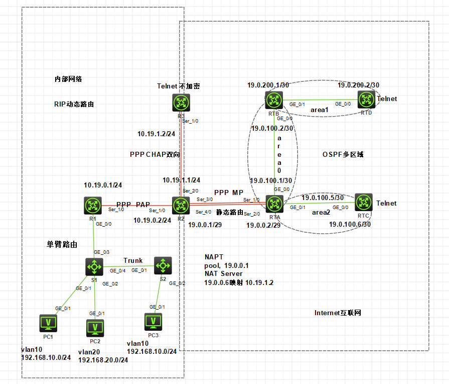
项目拓扑图:

在S1与S2之间运行Trunk协议使PC1与PC3通信
(PC1与PC3处于同一VLAN)。
注:两台交换机之间需要配置Trunk才能实现不同交换机下的同一个VLAN互相访问。
S1:
[H3C]sysname S1
[S1]vlan 10
[S1-vlan10]port g1/0/1
[S1-vlan10]vlan 20
[S1-vlan20]port g1/0/2
[S1-vlan20]int g1/0/4
[S1-GigabitEthernet1/0/4]port link-type trunk
[S1-GigabitEthernet1/0/4]port trunk permit vlan all
[S1-GigabitEthernet1/0/4]int g1/0/3
[S1-GigabitEthernet1/0/3]port link-type trunk
[S1-GigabitEthernet1/0/3]port trunk permit vlan all
[S1-GigabitEthernet1/0/3]qu
S2:
[H3C]sysname S2
[S2]vlan 10
[S2-vlan10]port g1/0/2
[S2-vlan10]qu
[S2]int g1/0/1
[S2-GigabitEthernet1/0/1]port link-type trunk
[S2-GigabitEthernet1/0/1]port trunk permit vlan all
在R1做单臂路由使PC1与PC2通信。
注:单臂路由就是在路由器以太网接口下配置若干个子接口,每个子接口对应一个VLAN,这样当路由器的以太网口连接到一个划分VLAN的二层交换机时,可以通过路由器的以太网口,实现二层交换机上多个VLAN之间的互通。而三层交换机的VLAN之间互通,则不需要路由器的配合,可在三层交换机上直接配置VLAN虚接口,每个VLAN一个虚接口,并指定IP,通过VLAN虚接口实现交换机各个VLAN之间的互通。
R1:
[R1]int g0/0.1
[R1-GigabitEthernet0/0.1]vlan-type dotlq vid 10
[R1-GigabitEthernet0/0.1]ip add 192.168.10.254 24
[R1-GigabitEthernet0/0.1]qu
[R1] int g0/0.2
[R1-GigabitEthernet0/0.2]vlan-type dotlq vid 20
[R1-GigabitEthernet0/0.2]ip add 192.168.20.254 24
[R1-GigabitEthernet0/0.2]qu
测试:

R1与R2之间运行PPP协议采用PAP认证;
注:PPP协议是一种点到点在串行链路上传输IP数据包的方法。MP可以增加设备之间的互联带宽,增加设备之间的链路可靠性,提高数据转发的效率。
R1:
[R1]int s1/0
[R1-Serial1/0]ip address 10.19.0.1 24
[R1-Serial1/0]local-user papr2 class network
New local user added.
[R1-luser-network-papr2]password simple 666
[R1-luser-network-papr2]service-type ppp
[R1-luser-network-papr2]qu
[R1]int s1/0
[R1-Serial1/0]ppp authentication-mode pap
R2:
[R2]int s1/0
[R2-Serial1/0]
[R2-Serial1/0]
[R2-Serial1/0]ip add 10.19.0.2 24
[R2-Serial1/0]ppp pap local-user papr2 password simple 666
[R2-Serial1/0]dis int s1/0
Serial1/0
Current state: UP
Line protocol state: UP
Description: Serial1/0 Interface
Band 64 kbps
Maximum transmission unit: 1500
Hold timer: 10 seconds, retry times: 5
Internet address: 10.19.0.2/24 (primary)
Link layer protocol: PPP
LCP: opened, IPCP: opened
Output queue - Urgent queuing: Size/Length/Discards 0/100/0
Output queue - Protocol queuing: Size/Length/Discards 0/500/0
Output queue - FIFO queuing: Size/Length/Discards 0/75/0
Last link flapping: 0 hours 5 minutes 25 seconds
Last clearing of counters: Never
Current system time:2021-03-14 13:39:57
Last time when physical state changed to up:2021-03-14 13:34:32
Last time when physical state changed to down:2021-03-14 13:34:27
R2与R3运行PPP协议采用CHAP双向认证;
R2:
[R2]local-user r3 class network
New local user added.
[R2-luser-network-r3]password simple 666
[R2-luser-network-r3]service-type ppp
[R2-luser-network-r3]qu
[R2]int s2/0
[R2-Serial2/0]ip add 10.19.1.1 24
[R2-Serial2/0]ppp authentication-mode chap
[R2-Serial2/0]ppp chap user r2
[R2-Serial2/0]
R3:
[H3C]sysname R3
[R3]local-user r2 class network
New local user added.
[R3-luser-network-r2]password simple 666
[R3-luser-network-r2]service-type ppp
[R3-luser-network-r2]qu
[R3]int s1/0
[R3-Serial1/0]ip add 10.19.1.2 24
[R3-Serial1/0]ppp chap user r3
[R3-Serial1/0]dis int s1/0
Serial1/0
Current state: UP
Line protocol state: UP
Description: Serial1/0 Interface
Band 64 kbps
Maximum transmission unit: 1500
Hold timer: 10 seconds, retry times: 5
Internet address: 10.19.1.2/24 (primary)
Link layer protocol: PPP
LCP: opened, IPCP: opened
Output queue - Urgent queuing: Size/Length/Discards 0/100/0
Output queue - Protocol queuing: Size/Length/Discards 0/500/0
Output queue - FIFO queuing: Size/Length/Discards 0/75/0
Last link flapping: 0 hours 5 minutes 36 seconds
Last clearing of counters: Never
Current system time:2021-03-14 13:53:35
Last time when physical state changed to up:2021-03-14 13:47:59
Last time when physical state changed to down:2021-03-14 13:47:54
为了加大带宽R2与RTA之间采用PPP MP捆绑:
R2:
[R2]int mp-group 1
[R2-MP-group1]ip address 19.0.0.1 29
[R2-MP-group1]qu
[R2]int s3/0
[R2-Serial3/0]ppp mp mp-group 1
[R2-Serial3/0]int s4/0
[R2-Serial4/0]ppp mp mp-group 1
[R2-Serial4/0]qu
RTA:
[RTA]int mp-group 1
[RTA-MP-group1]ip add 19.0.0.2 29
[RTA-MP-group1]int s1/0
[RTA-Serial1/0]ppp mp MP-group 1
[RTA-Serial1/0]int s2/0
[RTA-Serial2/0]ppp mp mp-group 1
[RTA]dis int mp-group 1
MP-group1
Current state: UP
Line protocol state: UP
Description: MP-group1 Interface
Band 128 kbps
Maximum transmission unit: 1500
Hold timer: 10 seconds, retry times: 5
Internet address: 19.0.0.2/29 (primary)
Link layer protocol: PPP
‘’’’’’’’’’’’’’’’’’’’’’’’’’’’’’略
内部网络采用RIP动态路由使内部网络互通;
注:OSPF多区域有利于改善网络的可扩展性,快速收敛。loopback地址叫回环地址,为了方便管理,会为每一台路由器创建一个loopback接口,并在该接口上单独指定一个IP地址作为管理地址,管理员使用该地址对路由器远程登录。
R1:
[R1]rip 10
[R1-rip-10]
[R1-rip-10]network 10.19.0.0 0.0.0.255
[R1-rip-10]network 192.168.10.0
[R1-rip-10]network 192.168.20.0
R2:
[R2]rip 10
[R2-rip-10]network 10.19.0.0 0.0.0.255
[R2-rip-10]network 10.19.1.0 0.0.0.255
R3:
[R3]rip 10
[R3-rip-10]network 10.19.1.0 0.0.0.255
RTA,RTB,RTC,RTD之间采用OSPF多区域路由配置loopback地址并宣告:
RTA:
<RTA>sys
System View: return to User View with Ctrl+Z.
[RTA]int g0/0
[RTA-GigabitEthernet0/0]ip add 19.0.100.1 30
[RTA-GigabitEthernet0/0]qu
[RTA]int loopback 0
[RTA-LoopBack0]ip add 1.1.1.1 32
[RTA-LoopBack0]qu
[RTA]int g0/1
[RTA-GigabitEthernet0/1]ip add 19.0.100.5 30
[RTA-GigabitEthernet0/1]qu
[RTA]
RTB:
[RTB]int g0/0
[RTB-GigabitEthernet0/0]ip add 19.0.100.2 30
[RTB-GigabitEthernet0/0]int g0/1
[RTB-GigabitEthernet0/1]ip add 19.0.200.1 30
[RTB-GigabitEthernet0/1]qu
[RTB]int loopback 0
[RTB-LoopBack0]ip add 1.1.1.2 32
[RTB-LoopBack0]qu
[RTB]
RTC:
[RTC]int g0/0
[RTC-GigabitEthernet0/0]ip add 19.0.100.6 30
[RTC-GigabitEthernet0/0]qu
[RTC]int loopback 0
[RTC-LoopBack0]ip add 1.1.1.3 32
[RTC-LoopBack0]qu
RTD:
[RTD]int g0/0
[RTD-GigabitEthernet0/0]ip add 19.0.200.2 30
[RTD-GigabitEthernet0/0]qu
[RTD]int loopback 0
[RTD-LoopBack0]ip add 1.1.1.4 32
[RTD-LoopBack0]qu
[RTD]
添加ospf:
RTA:
[RTA]ospf 100
[RTA-ospf-100]area 0
[RTA-ospf-100-area-0.0.0.0]network 1.1.1.1 0.0.0.0
[RTA-ospf-100-area-0.0.0.0]network 19.0.100.1 0.0.0.3
[RTA-ospf-100-area-0.0.0.0]qu
[RTA-ospf-100]area 2
[RTA-ospf-100-area-0.0.0.2]network 19.0.100.5 0.0.0.3
RTB:
[RTB]ospf 100
[RTB-ospf-100]area 0
[RTB-ospf-100-area-0.0.0.0]network 1.1.1.2 0.0.0.0
[RTB-ospf-100-area-0.0.0.0]network 19.0.100.2 0.0.0.3
[RTB-ospf-100-area-0.0.0.0]qu
[RTB-ospf-100]area 1
[RTB-ospf-100-area-0.0.0.1]network 19.0.200.1 0.0.0.3
[RTB-ospf-100-area-0.0.0.1]qu
RTC:
[RTC]
[RTC]ospf 100
[RTC-ospf-100]area 2
[RTC-ospf-100-area-0.0.0.2]network 1.1.1.3 0.0.0.0
[RTC-ospf-100-area-0.0.0.2]network 19.0.100.6 0.0.0.3
RTD:
[RTD]ospf 100
[RTD-ospf-100]area 1
[RTD-ospf-100-area-0.0.0.1]network 1.1.1.4 0.0.0.0
[RTD-ospf-100-area-0.0.0.1]network 19.0.200.2 0.0.0.3
[RTD-ospf-100-area-0.0.0.1]qu
R2与RTA之间运行静态路由:
RTA:
[RTA]ip route-static 10.19.0.0 255.255.0.0 19.0.0.1
[RTA]ospf 100
[RTA-ospf-100]import-route static
[RTA-ospf-100]import-route direct
[RTA-ospf-100]
R2:
[R2]ip route-static 0.0.0.0 0.0.0.0 19.0.0.2
R1:
[R1]ip route-static 0.0.0.0 0.0.0.0 10.19.0.2
R3:
[R3]ip route-static 0.0.0.0 0.0.0.0 10.19.1.1
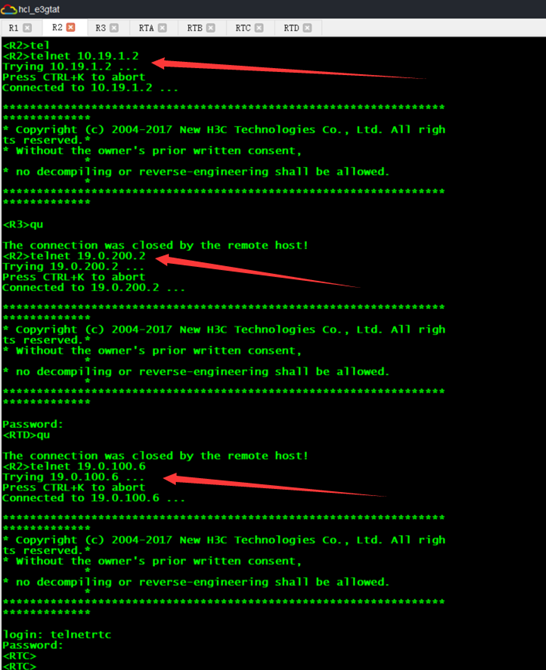
在R3上配置telnet服务不加密认证;在RTD上配置telnet服务并设置密码认证;在RTC上配置telnet服务并设置用户认证。
R3:
[R3]telnet server enable
[R3]line vty 0
[R3-line-vty0]authentication-mode none
[R3-line-vty0]
RTD:
[RTD]telnet server enable
[RTD]line vty 0
[RTD-line-vty0]authentication-mode password
[RTD-line-vty0]set authentication password simple 666
[RTD-line-vty0]user-role telnet-admin
[RTD-line-vty0]
RTC:
[RTC]telnet server enable
[RTC]line vty 0
[RTC-line-vty0]authentication-mode scheme
[RTC-line-vty0]qu
[RTC]local-user telnetrtc
New local user added.
[RTC-luser-manage-telnetrtc]password simple 666
[RTC-luser-manage-telnetrtc]service-type telnet
[RTC-luser-manage-telnetrtc]authorization-attribute user-role telnet-admin
测试:

在R2上做NAT服务使内部网络访问Internet;
注:NAT网络地址转换,实现内网的IP地址与公网的地址之间的相互转换,将大量的内网IP地址转换为一个或少量的公网IP地址,在一个局域网内,只需要一台计算机连接上Internet,就可以利用NAT共享Internet连接,使局域网内其他计算机也可以上网。使用NAT协议,局域网内的计算机可以访问Internet上的计算机,但Internet上的计算机无法访问局域网内的计算机。一方面减少对公网IP地址的占用,同时隐藏了内部网络结构,降低内部网络受到攻击的风险。
R2:
[R2]acl basic 2000
[R2-acl-ipv4-basic-2000]rule 0 permit source 192.168.0.0 0.0.255.255
[R2-acl-ipv4-basic-2000]rule 1 permit source 10.19.0.0 0.0.255.255
[R2-acl-ipv4-basic-2000]qu
[R2]nat address-group 1
[R2-address-group-1]address 19.0.0.3 19.0.0.6
[R2-address-group-1]qu
[R2]int mp-group 1
[R2-MP-group1]nat outbound 2000 address-group 1
[R2-MP-group1]qu
[R2]
在R2上配置NAT Server服务使RTD能正常访问R3的telnet服务:
[R2]interface mp-group 1
[R2-MP-group1]nat server protocol tcp global 19.0.200.2 telnet inside 10.19.1.3 telnet
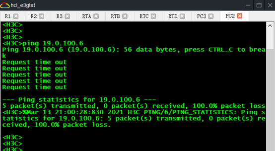
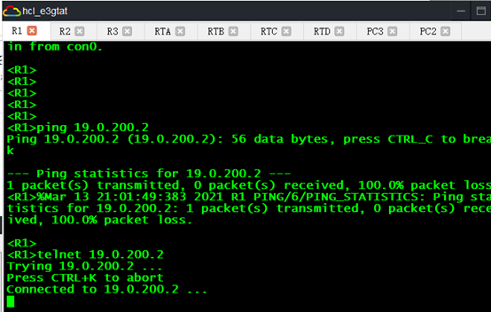
使用ACL访问控制列表实现:
访问控制列表(ACL)是应用在路由器接口的指令列表(即规则),这些指令列表用来告诉路由器,那些数据包可以接受,那些数据包需要拒绝。ACL使用包过滤技术,在路由器上读取OSI七层模型的第3层和第4层包头中的信息。如源地址、目标地址、源端口、目标端口等,根据预先定义好的规则对包进行过滤,从而达到访问控制的目的。
[R2]acl advanced 3000
[R2-acl-ipv4-adv-3000]rule deny ip source 192.168.10.1 0.0.0.0 destination 19.0.200.2 0.0.0.0
[R2-acl-ipv4-adv-3000]no rule 0
[R2-acl-ipv4-adv-3000]rule 0 deny ip source 192.168.20.1 0.0.0.0 destination 19.0.100.6 0.0.0.0
[R2-acl-ipv4-adv-3000]rule 1 deny 23 source 10.19.0.1 0.0.0.0 destination 19.0.200.2 0.0.0.0
[R2-acl-ipv4-adv-3000]qu
[R2]int s1/0
[R2-Serial1/0]packet-filter 3000 inbound
[R2-Serial1/0]qu
[R2]
禁止PC2访问RTC的所有服务:

禁止R1访问RTD的telnet服务:
 .
.
如有错误请大佬指正