Layer 2 Forwarding
Both store-and-forward and cut-through Layer 2 switches base their forwarding decisions on the destination MAC address of data packets. They also learn MAC addresses as they examine the source MAC (SMAC) fields of packets as stations communicate with other nodes on the network.
When a Layer 2 Ethernet switch initiates the forwarding decision, the series of steps that a switch undergoes to determine whether to forward or drop a packet is what differentiates the cut-through methodology from its store-and-forward counterpart.
Whereas a store-and-forward switch makes a forwarding decision on a data packet after it has received the whole frame and checked its integrity, a cut-through switch engages in the forwarding process soon after it has examined the destination MAC (DMAC) address of an incoming frame.
In theory, a cut-through switch receives and examines only the first 6 bytes of a frame, which carries the DMAC address. However, for a number of reasons, as will be shown in this document; cut-through switches wait until a few more bytes of the frame have been evaluated before they decide whether to forward or drop the packet.
Characteristics of Store-and-Forward Ethernet Switching
This section provides an overview of the functions and features of store-and-forward Ethernet switches.
Error Checking
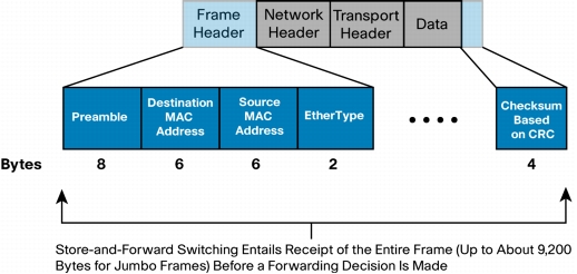
Figure 1 shows a store-and-forward switch receiving an Ethernet frame in its entirety. At the end of that frame, the switch will compare the last field of the datagram against its own frame-check-sequence (FCS) calculations, to help ensure that the packet is free of physical and data-link errors. The switch then performs the forwarding process.
Whereas a store-and-forward switch drops invalid packets, cut-through devices forward them because they do not get a chance to evaluate the FCS before transmitting the packet.
Automatic Buffering
The process of storing and then forwarding allows the switch to handle a number of networking conditions simply by the way it operates.
The ingress buffering process that a store-and-forward switch performs provides the flexibility to support any mix of Ethernet speeds, starting with 10 Mbps. For example, handling an incoming frame to a 1-Gbps Ethernet port that needs to be sent out a 10-Gbps interface is a fairly straightforward process. The forwarding process is made easier by the fact that the switch's architecture stores the entire packet.
Access Control Lists
Because a store-and-forward switch stores the entire packet in a buffer2, it does not have to execute additional ASIC or FPGA code to evaluate the packet against an access control list (ACL). The packet is already there, so the switch can examine the pertinent portions to permit or deny that frame.
Characteristics of Cut-Through Ethernet Switching
This section explores cut-through Ethernet switching. Because cut-through switching is not as well understood as store-and-forward switching, it is described in more detail than the store-and-forward technology.
Invalid Packets
Unlike store-and-forward switching, cut-through switching flags but does not get a chance to drop invalid packets. Packets with physical- or data-link-layer errors will get forwarded to other segments of the network. Then, at the receiving end, the host invalidates the FCS of the packet and drops the packet.
Timing of Cut-Through Forwarding
In theory, as indicated in Figure 2, a cut-through switch can make a forwarding decision as soon as it has looked up the DMAC address of the data packet. The switch does not have to wait for the rest of the packet to make its forwarding decision.
However, newer cut-through switches do not necessarily
take this approach. A cut-through switch may parse an incoming packet until it
has collected enough information from the frame content. It can then make a
more sophisticated forwarding decision, matching the richness of
packet-handling features that store-and-forward switches have offered over the
past 15 years.

EtherType Field
In preparation for a forwarding decision, a cut-through switch can fetch a predetermined number of bytes based on the value in EtherType field, regardless of the number of fields that the switch needs to examine. For example, upon recognizing an incoming packet as an IPv4 unicast datagram, a cut-through switch checks for the presence of a filtering configuration on the interface, and if there is one, the cut-through switch waits an additional few microseconds or nanoseconds to receive the IP and transport-layer headers (20 bytes for a standard IPv4 header plus another 20 bytes for the TCP section, or 8 bytes if the transport protocol is UDP). If the interface does not have an ACL for traffic to be matched against, the cut-through switch may wait for only the IP header and then proceed with the forwarding process. Alternatively, in a simpler ASIC implementation, the switch fetches the whole IPv4 and transport-layer headers and hence receives a total of 54 bytes up to that point, irrespective of the configuration. The cut-through switch can then run the packet through a policy engine that will check against ACLs and perhaps a quality-of-service (QoS) configuration.
Wait Time
With today's MAC controllers, ASICs, and ternary content addressable memory (TCAM), a cut-through switch can quickly decide whether it needs to examine a larger portion of the packet headers. It can parse past the first 14 bytes (the SMAC, DMAC, and EtherType) and handle, for example, 40 additional bytes in order to perform more sophisticated functions relative to IPv4 Layer 3 and 4 headers. At 10 Gbps, it may take approximately an additional 100 nanoseconds to receive the 40 bytes of the IPv4 and transport headers. In the context of a task-to-task (or process-to-process or even application-to-application) latency requirement that falls in a broad range, down to a demanding 10 microseconds for the vast majority of applications, that additional wait time is irrelevant. ASIC code paths are less complex when IP frames are parsed up to the transport-layer header with an insignificant latency penalty.
Multipath Distribution
Some sophisticated Layer 2 switches use fields beyond just the source and destination MAC addresses to determine the physical interface to use for sending packets across a PortChannel.
Cut-through switches fetch either only the SMAC and DMAC values or the IP and transport headers to generate the hash value that determines the physical interface to use for forwarding that frame across a PortChannel.
It is important to understand the level of PortChannel support in a given switch. Well-designed cut-through switches should be able to incorporate IP addresses and transport-layer port numbers to provide more flexibility in distributing packets across a PortChannel.
IP ACLs
A well-designed cut-through Ethernet switch should support ACLs to permit or deny packets based on source and destination IP addresses and on TCP and UDP source and destination port numbers. Even though the switch is operating at Layer 2, it should be able to filter packets based on Layers 3 and 4 of the Open System Interconnection (OSI) Protocol stack.
With ASIC abilities to, in a few nanoseconds, parse packets and execute a number of instructions in parallel or in a pipeline, the application of an input or output ACL for a particular interface should not exact a performance penalty. In fact, given more flexible and simpler ASIC code paths, an IPv4 or IPv6 packet will have a predetermined number of bytes submitted to the policy engine to evaluate extremely quickly the results of any ACL configurations.
With or without ACLs, in a configuration that does or does not have a PortChannel, cut-through switching has a latency advantage over store-and-forward switching if the packet sizes are several thousand bytes. Otherwise, cut-through and store-and-forward switching can provide very similar performance characteristics.
Ethernet Speeds
If a switch uses a fabric architecture, ports running at 1 Gbps are considered slow compared with that fabric, which expects to handle a number of higher-speed interfaces typically at wire rate. In addition, well-designed switch fabrics offer a "speedup" function into the fabric to reduce contention and accommodate internal switch headers. For example, if a switch fabric is running at 12 Gbps, the slower 1-Gbps ingress port will typically buffer an incoming frame before scheduling it across the fabric to the proper destination port(s). In this scenario, the cut-through switch functions like a store-and-forward device.
Furthermore, if the rate at which the switch is receiving the frame is not as fast as or faster than the transmit rate out of the device, the switch will experience an under-run condition, whereby the transmitting port is running faster than the receiver can handle. A 10-Gbps egress port will transmit 1 bit of the data in one-tenth the time of the 1-Gbps ingress interface. The transmit interface has to wait for nine bit-times (0.9 nanoseconds) before it sees the next bit from the 1-Gbps ingress interface. So to help ensure that no bit "gaps" occur on the egress side, a whole frame must be received from a lower-speed Ethernet LAN before the cut-through switch can transmit the frame.
In the reverse situation, whereby the ingress interface is faster than the egress port, the switch can still perform cut-through switching, by scheduling the frame across the fabric and performing the required buffering on the egress side.
Egress Port Congestion
Some congestion conditions also cause the cut-through switch to store the entire frame before acting on it. If a cut-through switch has made a forwarding decision to go out a particular port while that port is busy transmitting frames coming in from other interfaces, the switch needs to buffer the packet on which it has already made a forwarding decision. Depending on the architecture of the cut-through switch, the buffering can occur in a buffer associated with the input interface or in a fabric buffer. In this case, the frame is not forwarded in a cut-through fashion.
In a well-designed network, access-layer traffic coming in from a client does not usually exceed the capacity of an egress port or PortChannel going out to a server. The more likely scenario where port contention may occur is at the distribution (aggregation) layer of the network. Typically, an aggregation switch connects a number of lower-speed user interfaces to the core of the network, where an acceptable oversubscription factor should be built into the network's design. In such cases, cut-through switches function the same way as store-and-forward switches.
IEEE 802.1D Bridging Specification
Although cut-through switching may violate the IEEE 802.1D bridging specification when not validating the frame's checksum, the practical effect is much less dramatic, since the receiving host will discard that erroneous frame, with the host's network interface card (NIC) hardware performing the discard function without affecting the host's CPU utilization (as it used to do, in the 1980s). Furthermore, with modern Ethernet wiring and connector infrastructures installed over the past 5 years or more, hosts should not find many invalid packets that they need to drop.
From a network monitoring perspective, Layer 2 cut-through switches keep track of Ethernet checksum errors encountered.
In comparison, Layer 3 IP switching cannot violate IP routing requirements, as specified in RFC 1812, since it modifies every packet it needs to forward. The router must make the necessary modifications to the packet, or else every frame that the router sends will contain IP-level as well as Ethernet-layer errors that will cause the end host to drop it.