B4及之后:为谷歌软件定义WAN的可用性和扩展管理层次化、划分和不对称
本文为SIGCOMM 2018会议论文,由谷歌提供。
笔者翻译了该论文。由于时间仓促,且笔者英文能力有限,错误之处在所难免;欢迎读者批评指正。
本文及翻译版本仅用于学习使用。如果有任何不当,请联系笔者删除。
ABSTRACT (摘要)
Private WANs are increasingly important to the operation of enterprises, telecoms, and cloud providers. For example, B4, Google’s private software-defned WAN, is larger and growing faster than our connectivity to the public Internet. In this paper, we present the five-year evolution of B4. We describe the techniques we employed to incrementally move from offering best-effort content-copy services to carrier-grade availability, while concurrently scaling B4 to accommodate 100x more traffic. Our key challenge is balancing the tension introduced by hierarchy required for scalability, the partitioning required for availability, and the capacity asymmetry inherent to the construction and operation of any large-scale network. We discuss our approach to managing this tension: i) we design a custom hierarchical network topology for both horizontal and vertical software scaling, ii) we manage inherent capacity asymmetry in hierarchical topologies using a novel traffic engineering algorithm without packet encapsulation, and iii) we re-architect switch forwarding rules via two-stage matching/hashing to deal with asymmetric network failures at scale.
私有广域网对企业、电信和云提供商的运维来说正变得越来越重要。例如,谷歌的私有软件定义广域网B4的连接规模和增长速度超过其到公共因特网的连接。本文中,我们介绍了B4系统的5年演进过程。我们描述了提供由尽力而为的内容拷贝服务到电信级可用性逐渐转变的技术,同时B4系统扩展到适应100倍以上的通信量。我们的关键挑战是均衡以下因素导致的矛盾:可扩展性要求的层次化、可用性要求的网络划分以及任何大规模网络构建和运维所固有的容量不对称。我们讨论了解决这一矛盾的方法:1)我们为水平和垂直软件扩展设计了一种定制的层次化网络拓扑,2)我们在层次化拓扑中使用一种创新的无需数据包封装的流量工程算法来解决固有的容量不对称,和3)我们通过两阶段匹配/哈希重构了交换机转发规则,以解决一定规模下的不对称网络故障问题。
1 Introduction (引言)
B4 [18] is Google’s private backbone network, connecting data centers across the globe (Figure 1). Its software-defned network control stacks enable flexible and centralized control, offering substantial cost and innovation benefts. In particular, by using centralized traffic engineering (TE) to dynamically optimize site to site pathing based on utilization and failures, B4 supports much higher levels of utilization and provides more predictable behavior.
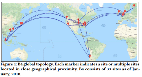
图1: B4全球拓扑。每个标记点表明单个站点或多个地理位置接近的站点。截止到2018年1月,B4包含33个站点。
B4[18]是谷歌用来连接其全球数据中心的私有骨干网络(见图1)。它所采用的软件定义网络控制栈具有灵活的和集中的网络管理能力,带来极大的成本和革新效益。具体地讲,使用集中式流量工程(TE)基于利用率和故障动态优化站间选路,B4支持更高级别的利用率,提供更具预测性地行为。
B4’s initial scope was limited to loss-tolerant, lower availability applications that did not require better than 99% availability, such as replicating indexes across data centers. However, over time our requirements have become more stringent, targeting applications with service level objectives (SLOs) of 99.99% availability. Specifcally, an SLO of X% availability means that both network connectivity (i.e., packet loss is below a certain threshold) and promised bandwidth [25] between any pair of datacenter sites are available X% of the minutes in the trailing 30-day window. Table 1 shows the classifcation of applications into service classes with the required availability SLOs.
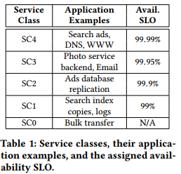
表1:服务等级及他们对应的应用示例,以及为他们分配的可用性SLO。
B4的初始范围只限于容丢失的低可用性应用,这些应用不需要高于99%的可用性(如跨数据中心索引复制)。然而,随着时间的迁移,我们的需求变得更为严格,以服务水平目标(SLOs)为99.99%可用性的应用为目标。具体地,SLO为X%可用性指的是任意一对数据中心站点间的网络连通性(即,数据丢包低于某一阈值)和许诺带宽[25]在30天的时间窗口内的可用分钟数达到X%[笔者注:30天包含43200分钟,则10%的可用性要求可用分钟数达到4320分钟]。表1给出应用到服务等级的分类,这些服务等级具有指定的可用性SLO。
Matching the reported availability of carrier-grade networks initially appeared daunting. Given the inherent unreliability of long-haul links [17] as well as unavoidable downtime associated with necessary management operations [13], conventional wisdom dictates that this level of availability requires substantial over-provisioning and fast local failure recovery, e.g., within 50 milliseconds [7].
初看起来,匹配电信级网络的可用性是令人畏惧的。考虑长距离传输链路的固有不可靠性[17]和不可避免的与必要的管理操作相关的宕机[13],传统的知识认为达到这一等级的可用性(电信级可用性)需要大量的超额配置和快速本地故障恢复(如50毫秒内[7])。
Complicating our push for better availability was the exponential growth of WAN traffic; our bandwidth requirements have grown by 100x over a fve year period. In fact, this doubling of bandwidth demand every nine months is faster than all of the rest of our infrastructure components, suggesting that applications derive signifcant benefts from plentiful cluster to cluster bandwidth. This scalability requirement spans multiple dimensions, including aggregate network capacity, the number of data center sites, the number of TE paths, and network aggregate prefixes. Moreover, we must achieve scale and availability without downtime for existing traffic. As a result, we have had to innovate aggressively and develop novel point solutions to a number of problems.
广域网流量的指数增长使我们对更高可用性的努力复杂化;我们的带宽需求在5年期间增长了100倍。事实上,带宽需求每九个月翻一番的速度比其它基础设施组件更快,表明应用可以从大量的集群到集群带宽中显著受益。可扩展性需求包含多个维度,包括聚合网络容量、数据中心站点数目、TE路径数量和网络聚合前缀。此外,我们必须在不导致现有数据流中断的情形下获得扩展性和可用性。因此,我们需要激进地革新并研发解决多个问题的创新点方案。
In this paper, we present the lessons we learned from our fve-year experience in managing the tension introduced by the network evolution required for achieving our availability and traffic demand requirements (§2). We gradually evolve B4 into a hierarchical topology (§3) while developing a decentralized TE architecture and scalable switch rule management (§4). Taken together, our measurement results show that our design changes have improved availability by two orders of magnitude, from 99% to 99.99%, while simultaneously supporting an increase in traffic scale of 100x over the past fve years (§6)
本文中,我们介绍了过去5年在解决网络演进导致的矛盾方面的经验教训;网络演进是取得我们可用性和流量需求所必须的(第二部分)。我们将B4逐渐演化为一种层次化拓扑(第三部分),同时研发了一种去中心化的TE架构和可扩展交换机规则管理方法(第四部分)。总体来看,实验结果表明我们的设计改变将可用性提升了两个量级(由99%提高到99.99%),同时在过去5年支持了100倍的流量增长(第6部分)。
2 BACKGROUND AND MOTIVATION (背景和动机)
In this section, we present the key lessons we learned from our operational experience in evolving B4, the motivating examples which demonstrate the problems of alternative design choices, as well as an outline of our developed solutions.
本节,我们给出B4演进过程中运维方面的经验教训,展示其它设计选择问题的动机性实例,以及我们设计方案的概要。
2.1 Flat topology scales poorly and hurts availability (扁平拓扑扩展性差且损害可用性)
We learned that existing B4 site hardware topologies imposed rigid structure that made network expansion difficult. As a result, our conventional expansion practice was to add capacity by adding B4 sites next to the existing sites in a close geographical proximity. However, this practice led to three problems that only manifested at scale. First, the increasing site count signifcantly slowed the central TE optimization algorithm, which was operated at site-level topology. The algorithm run time increased super-linearly with the site count, and this increasing runtime caused extended periods of traffic blackholing during data plane failures, ultimately violating our availability targets. Second, increasing the site count caused scaling pressure on limited space in switch forwarding tables. Third, and most important, this practice complicated capacity planning and confused application developers. Capacity planning had to account for inter-site WAN bandwidth constraints when compute and storage capacity were available in the close proximity but behind a different site. Developers went from thinking about regional replication across clusters to having to understand the mapping of cluster to one of multiple B4 sites.
现有的B4站点硬件拓扑使用刚性结构,导致网络难于扩展。其结果是,我们传统的扩展方法是通过增加B4站点的方式增加容量;增加的B4站点与现有站点在地理位置邻近。然而,这种方法导致三个问题,这些问题只在一定规模后才会呈现。首先,站点数量的增加导致集中TE优化算法(在站点级拓扑下运行)显著变慢。随着站点数量的增加,算法的运行时间超线性增长;运行时间的增长导致数据平面故障期间数据流黑洞的时间延长,最终违反我们的可用性目标。其次,站点数量的增加导致有限交换机转发表空间方面的扩展压力。最后,最重要的是,这种方法使容量规划复杂化并混淆应用开发者。当计算和存储容量在邻近点(一个不同的站点之后)可用时,容量规划必须考虑站点间的WAN带宽约束。开发者由考虑跨集群的区域复制转变到必须理解集群到多个B4站点中一个站点的映射。
To solve this tension introduced by exponentially increasing bandwidth demands, we redesign our hardware topology to a hierarchical topology abstraction (details in Figure 4 and §3). In particular, each site is built with a two-layer topology abstraction: At the bottom layer, we introduce a “supernode” fabric, a standard two-layer Clos network built from merchant silicon switch chips. At the top layer, we loosely connect multiple supernodes into a full mesh topology to manage incremental expansion and inherent asymmetries resulting from network maintenance, upgrades and natural hardware/software failures. Based on our operational experience, this two-layer topology provides scalability, by horizontally adding more supernodes to the top layer as needed without increasing the site count, and availability, by vertically upgrading a supernode in place to a new generation without disrupting existing traffic.
为了解决带宽需求指数增长引入的矛盾,我们重新设计了硬件拓扑为层次化拓扑抽象(细节见图4和第三部分)。具体地讲,每个站点构建为2层拓扑抽象:在底层,我们引入"超级节点”结构(由商用硅交换芯片构建的标准两层Clos网络);在上层,我们松散的链接多个超级节点构成一个全mesh拓扑,以解决增量扩展和网络维护、升级及软硬件故障导致的固有不对称。基于我们的运维经验,这种两层拓扑提供了可扩展性(按需向上层水平增加更多的超级节点,而不需要增加站点数量)和可用性(垂直就地升级超级节点为新一代设备,而无需打断现有流量)。
2.2 Solving capacity asymmetry in hierarchical topology (解决层次化拓扑中的容量不对称)
The two-layer hierarchical topology, however, also causes challenges in TE. We fnd that capacity asymmetry is inevitable at scale due to inherent network maintenance, operation, and data plane device instability. We design our topology to have symmetric WAN capacity at the supernode level, i.e., all supernodes have the same outgoing confgured capacity toward other sites. However, Figure 2 shows that 6-20% of the site-level links in B4 still have > 5% capacity asymmetry. We defne capacity asymmetry of a site-level link as (avg∀i(Ci) - min∀i(Ci))/avg∀i(Ci), where Ci is the total active capacity of each supernode i toward next site.
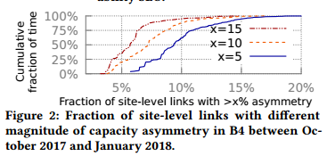
图2: 2017年10月到2018年1月,B4中具有不同量级容量不对称的站点级链路的比例。
然而,2层层次化拓扑给TE带来挑战。我们发现,由于固有的网络维护、运维和数据平面设备的不稳定,在一定规模下容量不对称问题是不可避免的。我们设计的拓扑在超级节点级具有对称的WAN容量,即所有的超级节点具有相同的向其它站点的出口容量。然而,图2表明B4中6-20%的站点级链路仍然具有大于5%的容量不对称。我们定义站点级链路的容量不对称为(avg∀i(Ci) - min∀i(Ci))/avg∀i(Ci),这里Ci表示超级节点i向其它相邻站点的总活跃流量。
Moreover, we fnd that capacity asymmetry signifcantly impedes the efficiency of our hierarchical topology—In about 17% of the asymmetric site-level links, we have 100% site level abstraction capacity loss because at least one supernode completely loses connectivity toward another site. To understand why capacity asymmetry management is critical in hierarchical topologies, we frst present a motivating example. Figure 3a shows a scenario where supernodes A1 and A2 respectively have 10 and 2 units of active capacity toward site B, resulting from network operation or physical link failure. To avoid network congestion, we can only admit 4 units of traffic to this site-level link, because of the bottlenecked supernode A2 which has lower outgoing capacity. This indicates that 8 units of supernode-level capacity are wasted, as they cannot be used in the site-level topology due to capacity asymmetry.
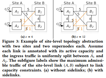
图3: 包含2个站点且每个站点包含2个超级节点的站点级拓扑示例。每条链路上的标注表示该链路的有效容量,入口流量在A1和A2之间平均分配。子图给出受限于链路容量,站点级链路(A,B)的最大准入流量。(a)没有旁路;(b)包含旁路。
此外,我们发现容量不对称显著抑制了层次化拓扑的效率—在约17%的不对称站点级链路中,具有100%的站点级抽象容量损失,这是因为至少一个超级节点完全失去到另一个站点的链接。为了理解层次化次拓扑中容量不对称管理的重要性,我们首先给出一个动机性实例。图3a中超级节点A1和A2到站点B分别有10和2个单位的有效容量,这是由网络运维或物理链路故障导致的。由于瓶颈超级节点A2具有更低的出口容量,为了避免网络拥塞,此站点级链路仅允许4个单位的流量。这表明有8个单位的超级节点级容量是浪费的,因为容量不对称导致他们无法在站点级拓扑中使用。
To reduce the inefficiency caused by capacity asymmetry, we introduce sidelinks, which interconnect supernodes within a site in a full mesh topology. Figure 3b shows how the use of sidelinks increases admissible traffic volume by 3x in this example. The central controller dynamically rebalances traffic within a site to accommodate asymmetric WAN link failures using these sidelinks. Since supernodes of a B4 site are located in close proximity, sidelinks, like other datacenter network links, are much cheaper and signifcantly more reliable than long-haul WAN links. Such heterogeneous link cost/reliability is a unique WAN characteristic which motivates our design. The flexible use of sidelinks with supernode level TE not only improves WAN link utilization but also enables incremental, in-place network upgrade, providing substantial up-front cost savings on network deployment. Specifcally, with non-shortest-path TE via sidelinks, disabling supernode-level links for upgrade/maintenance does not cause any downtime for existing traffic—It merely results in a slightly degraded site-level capacity.
为了减少容量不对称导致的低效问题,我们引入了旁路(sidelink)的概念;旁路互连同一站点中的超级节点构成全mesh拓扑。图3b展示了如何通过使用旁路将本例中的准入流量增加3倍。集中控制器利用旁路动态重均衡站点内的数据流以适应不对称WAN链路故障。由于B4站点内的超级节点的位置是邻近的,与其他数据中心网络链路类似,旁路的价格更为低廉且比长传输距离的WAN链路更为可靠。这种异构链路的成本/可靠性是驱动我们设计的独特WAN特征。旁路的灵活使用配合超级节点级TE不仅提高了WAN链路的利用率,并且使得增量式就地网络升级成为可能,极大地降低了网络部署的预付成本。具体地,使用旁路的非最短路径TE,因升级/维护而断掉超级节点级链路不会导致任何现有流量的中断。即,仅导致站点级容量的轻微退化。
Evolving the existing site-level TE to a hierarchical TE (site-level, and then supernode-level) turned out to be challenging. TE typically requires tunnel encapsulation (e.g., via MPLS label [34], IP-in-IP encapsulation [30], or VLAN tag [3]), while off-the-shelf commodity switch chips can only hash on either the inner or outer layer packet header. With two layers of tunnel encapsulation, the packet header in both the inner and outer layer has very low entropy, making it impossible to enforce traffic splits. Another option is to overwrite the MAC address on each packet as a tag for supernode-level TE. However, we already reserve MAC addresses for more efficient hashing (§5). To solve this, we design and implement a novel intra-site TE algorithm (§4) which requires no packet tagging/encapsulation. Moreover, we fnd that our algorithm is scalable, by taking 200-700 milliseconds to run at our target scale, and effective, by reducing capacity loss due to topology abstraction to 0.6% on a typical site-level link even in the face of capacity asymmetry.
将现有的站点级TE演化为层次化TE(站点级,其后是超级节点级)证明是具有挑战性的。TE通常需要隧道封装(如,MPLS标签[34],IP-in-IP封装[30]或VLAN标签[3]),然而商用交换机芯片只能依据数据包内部或者外部报头进行哈希计算。使用两层隧道封装,内部和外部数据报头均只有非常低的熵值,导致无法实施流量切分。另一种可选方案是重写每个数据包的MAC地址作为超级节点级TE的标签。然而,我们已经保留MAC地址以实行更有效的哈希计算(第五部分)。为了解决这个问题,我们设计和实现了新型站点内TE算法(第四部分),该算法不需要数据包打标/封装。此外,该算法是可扩展的,在目标规模下运行时间为200-700毫秒;该算法是高效的,在典型站点级链路上,即使在容量不对称问题存在时也可减少拓扑抽象导致的容量损失到0.6%。
A further challenge is that TE updates can introduce routing blackholes and loops. With pre-installed tunnels, steering traffic from one tunnel to another is an atomic operation, as only the ingress source node needs to be updated to encapsulate traffic into a different tunnel. However, removing tunnel encapsulation complicates network updates. We fnd that applying TE updates in an arbitrary order results in more than 38% packet blackholing from forwarding loops in 2% of network updates (§6.3). To address this issue, earlier work enables loop-free update with two-phase commit [31] and dependency tree/forest based approach [28]. More recently, Dionysus [21] models the network update as a resource scheduling problem and uses critical path scheduling to dynamically find a feasible update schedule. However, these efforts assume tunneling/version tagging, leading to the previously described hashing problem for our hierarchical TE. We develop a simple dependency graph based solution to sequence supernode-level TE updates in a provably blackhole/loop free manner without any tunneling/tagging (§4.4).
另一个挑战是TE升级可能会引入路由黑洞和环路。使用预设隧道,由于只有入口源节点需要更新从而将流量封装到一个不同的隧道,将流量由一个隧道导向另一个隧道是的过程是原子操作。然而,移除隧道封装使网络更新复杂化。我们发现,以任意顺序应用TE更新导致2%的网络更新的前向环路中有多达38%的数据包黑洞(见6.3节)。为了解决这个问题,前期工作采用两阶段提交[31]和基于依赖树/森林的方法[28]实现无环更新。最近,Dionysus[21]将网络更新建模为资源调度问题,并使用关键路径调度来动态搜索可行的更新调度方法。然而,这些工作假设隧道/版本打标,对我们的层次化TE来说,导致前文所描述的哈希问题。我们开发了一种简单的基于依赖图的方法,排定超级节点级TE更新操作的顺序,其是可证明无黑洞/环路的,而且不需要任何隧道/标签(见4.4节)。
2.3 Efcient switch rule management (高效交换机规则管理)
Merchant silicon switches support a limited number of matching and hashing rules. Our scaling targets suggested that we would hit the limits of switch matching rules at 32 sites using our existing packet forwarding pipeline. On the other hand, hierarchical TE requires many more switch hashing entries to perform two-layer, fne-grained traffic splitting. SWAN [16] studied the tradeoffs between throughput and the switch hashing rule limits and found that dynamic tunneling requires much fewer hashing rules than a fxed tunnel set. However, we fnd that dynamic tunneling in hierarchical TE still requires 8x more switch hashing rules than available to achieve maximal throughput at our target scale.
商用硅交换机支持有限数量的匹配和哈希规则。使用我们现有的包转发流水线,在32个站点时,我们将达到交换机匹配规则的数量限制。另一方面,层次化TE需要更多的交换机哈希项来执行两层的细粒度流量划分。SWAN[16]研究了吞吐量和交换机哈希规则限制之间的权衡,发现动态隧道化比静态隧道集合需要更少的哈希规则。然而,我们发现在层次下TE下采用动态隧道化仍然需要比达到目标规模下的最大吞吐量所需要的交换机哈希规则多8倍以上。
We optimize our switch forwarding behavior with two mechanisms (§5). First, we decouple flow matching rules into two switch pipeline tables. We fnd this hierarchical, two-phase matching mechanism increases the number of supported sites by approximately 60x. Second, we decentralize the path split rules into two-stage hashing across the edge and the backend stage of the Clos fabric. We fnd this optimization is key to hierarchical TE, which otherwise would offer 6% lower throughput, quite substantial in absolute terms at our scale, due to insufficient traffic split granularity.
我们使用两种机制优化交换机转发行为(第五部分)。首先,我们将流匹配规则分解到两个交换机流水表。我们发现这种层次化的两阶段匹配机制将支持的站点数目增加了接近60倍。其次,我们将路径分割规则去中心化为跨Clos设施边缘和后端阶段的2阶段哈希。我们发现这种优化方法是层次化TE的关键,将吞吐量提升6%(在我们的规模下,就绝对值来说是非常大的),这是因为不采用这种优化方法导致流量划分粒度不足。
3 SITE TOPOLOGY EVOLUTION (站点拓扑演化)
Table 2 summarizes how B4 hardware and the site fabric topology abstraction have evolved from a flat topology to a scalable two-stage hierarchy over the years. We next present Saturn (§3.1), our frst-generation network fabric, followed by Jumpgate (§3.2), a new generation of site network fabrics with improved hardware and topology abstraction.
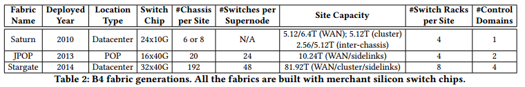
表2:B4设施代次。所有的设施均有常用硅交换芯片构建。
表2总结了B4硬件和站点设施拓扑如何由扁平拓扑逐年演化为可扩展的两阶段层次化拓扑。我们接下来讨论我们第一代网络设施Saturn(见3.1节),接着讨论新一代站点网络设施Jumpgate(见3.2节);jumpgate提升了硬件和拓扑结构。
3.1 Saturn
Saturn was B4’s frst-generation network fabric, deployed globally in 2010. As shown in Figure 4, the deployment consisted of two stages: A lower stage of four Saturn chassis, offering 5.12 Tbps of cluster-facing capacity, and an upper stage of two or four Saturn chassis, offering a total of 3.2 Tbps and 6.4 Tbps respectively toward the rest of B4. The difference between cluster and WAN facing capacity allowed the fabric to accommodate additional transit traffic. For availability, we physically partitioned a Saturn site across two buildings in a datacenter. This allowed Saturn sites to continue operating, albeit with degraded capacity, if outages caused some or all of the devices in a single building to become unreachable. Each physical rack contained two Saturn chassis, and we designed the switch to rack mapping to minimize the capacity loss upon any single rack failure.
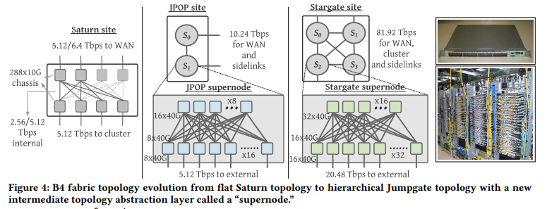
图4:B4设施由扁平Saturn拓扑到层次化Jumpgate拓扑的演化;Jumpgate包含一个称为超级节点的抽象层。
Saturn是B4的第一代网络设施,2010年在全球部署。如图4所示,部署包括两个步骤:4个Saturn底架构成的底层,提供5.12Tbps的面向集群的容量;由2个或4个底架构成的上层,向B4的其他部分分别提供3.2 Tbps和6.4 Tbps的容量。面向集群和WAN的容量的差异使得设施可以提供额外的中转流量。针对可用性,我们将单一Saturn的站点从物理上划分到数据中心的两个建筑。这使得Saturn站点可以在容量降低的情形下仍然工作(单一建筑中的某些或者所有设备不可达)。每个物理机架包含2个Saturn底架,我们设计交换机到机架映射使得任意单机架故障情形下容量损失最小化。
3.2 Jumpgate
Jumpgate is an umbrella term covering two flavors of B4 fabrics. Rather than inheriting the topology abstraction from Saturn, we recognize that the flat topology was inhibiting scale, and so we design a new custom hierarchical network topology in Jumpgate for both horizontal and vertical scaling of site-level capacity without impacting the scaling requirements of control software. As shown in Figure 4, we introduce the concept of a supernode as an intermediate topology abstraction layer. Each supernode is a 2-stage folded-Clos network. Half the ports in the lower stage are external-facing and can be flexibly allocated toward peering B4 sites, cluster fabrics, or other supernodes in the same site. We then build a Jumpgate site using a full mesh topology interconnecting supernodes. These intra-site links are called sidelinks. In addition, B4’s availability in Saturn was signifcantly reduced by having a single control domain per site. We had a number of outages triggered by a faulty domain controller that caused widespread damage to all trafc passing through the affected site. Hence, in Jumpgate we partition a site into multiple control domains, one per supernode. This way, we improve availability by reducing the blast radius of any domain controller fault to traffic transiting a single supernode.
Jumpgate是覆盖两种B4设施特点的涵盖性术语。与其继承Saturn的拓扑结构,我们意识到扁平拓扑会限制扩展性,因此我们在Jumpgate中设计了一种新的定制的层次化网络拓扑;Jumpgate为站点级容量提供水平和垂直扩展,而不影响控制软件的扩展需求。如图4所示,我们引入超级节点作为中间拓扑抽象层。每个超级节点是一个2阶段folded-Clos网络。底层的一半端口是面向外部的,可以灵活地分配给对等B4站点、集群设施或者同一站点内其它的超级节点。接着,我们使用互连超级节点的全mesh拓扑构建Jumpgate站点。这些互连链路称为旁路。此外,由于每个站点只有一个控制域,Saturn中B4的可用性显著降低。我们观察到大量的由域控制器故障导致的中断,这会广泛损害所有途径受影响站点的数据流。因此,Jumpgate中将站点划分为多个控制域,每个超级节点一个控制域。采用这种方式,通过减少任意域控制器故障的爆炸半径到途径单一超级节点的数据流,提升了B4的可用性。
We present two generations of Jumpgate where we improve availability by partitioning the site fabric into increasingly more supernodes and more control domains across generations, as shown in Figure 4. This new architecture solves the previously mentioned network expansion problem by incrementally adding new supernodes to a site with flexible sidelink reconfgurations. Moreover, this architecture also facilitates seamless fabric evolution by sequentially upgrading each supernode in place from one generation to the next without disrupting traffic in other supernodes.
我们展示了两代Jumpgate,不同代次间站点划分为更多的超级节点和控制域,从而提升了可用性,如图4所示。这种新型架构解决了先前提到的网络扩展问题;解决方案是使用灵活的旁路重配和增量增加站点内的超级节点数量。此外,这种架构通过依次升级每个超级节点(由某一代到下一代)为无缝设施演进提供了便利,并且无需干扰其他超级节点的流量。
Jumpgate POP (JPOP): Strategically deploying transitionly sites improves B4’s overall availability by reducing the network cable span between datacenters. Transit sites also improve site-level topology “meshiness,” which improves centralized TE’s ability to route around a failure. Therefore, we develop JPOP, a low-cost confguration for lightweight deployment in the transit POP sites supporting only transit traffic. Since POP sites are often constrained by power and physical space, we develop JPOP with high bandwidth density 16x40G merchant silicon (Figure 4), requiring a smaller number of switch racks per site.
JPOP:通过减少数据中心间网络线缆的跨度,战略性部署中转站点提升了B4的总可用性。中转站点同时提高了站点级拓扑的“meshiness”,进而提升了集中TE绕过故障的能力。因此,我们开发了JPOP,一种用于只支持中转流量的中转POP站点轻量级部署的低成本配置方案。由于POP站点通常受到电源和物理空间的限制,我们使用高带宽密度16x40G商用硅(图4)构建JPOP,因此每个站点只需要少量的交换机机架。
Stargate: We globally deprecate Saturn with Stargate, a large network fabric to support organic WAN traffic demand growth in datacenters. A Stargate site consists of up to four supernodes, each a 2-stage folded-Clos network built with 32x40G merchant silicon (Figure 4). Stargate is deployed in datacenters and can provide up to 81.92 Tbps site-external capacity that can be split among WAN, cluster and sidelinks. Compared with Saturn, Stargate improves site capacity by more than 8x to keep up with growing traffic demands. A key for this growth is the increasing density of forwarding capacity in merchant silicon switch chips, which enables us to maintain a relatively simple topology. The improved capacity allows Stargate to subsume the campus aggregation network. As a result, we directly connect Stargate to Jupiter cluster fabrics [32], as demonstrated in Figure 5. This architecture change simplifes network modeling, capacity planning and management.

图5:Stargate纳入园区汇聚网络。
Stargate: 我们在全球范围内使用Stargate替代Saturn。Stargate是一种支持数据中心WAN流量需求增长的大型网络设施。Stargate站点由多达4个超级节点构成,每个超级节点由32x40G商用硅(图4)构建成2阶段folded-Clos网络。Stargate部署于数据中心,可以提供高达81.92 Tbps的站点到外部容量,这些容量可以在WAN、集群和旁路间划分。与Saturn相比,Stargate将站点容量提升了8倍以上,从而满足增长的流量需求;这种增长的关键是商用硅交换芯片中转发容量密度的增长,使得我们可以维护相对简单的拓扑。容量的提升使得Stargate可以纳入园区汇聚网络。其结果是,我们可以直接将Stargate链接到Jupiter集群设施[32],如图5所示。架构改变简化了网络建模、容量规划和管理。
4 HIERARCHICAL TRAFFIC ENGINEERING (层次化流量工程TE)
In this section, we start with two straw-man proposals for the capacity asymmetry problem (§4.1). We solve this problem by evolving from flat TE into a hierarchical TE architecture (§4.2) where a scalable, intra-site TE algorithm is developed to maximize site-level link capacity (§4.3). Finally, we present a dependency-graph based algorithm to sequence the supernode-level rule updates (§4.4). Both algorithms are highly scalable, blackhole and loop free, and do not require packet encapsulation/tagging.
本节,我们以两个解决容量不对称问题的稻草人方案为起始(见4.1节):我们通过扁平化TE演化为层次化TE架构解决这个问题(见4.2节),开发了一种可扩展的站内TE算法,最大化站点间链路容量(见4.3节)。最后,我们给出了基于依赖图的超级节点级规则升级序列算法(见4.4节)。这些算法均是可扩展,无黑洞和环路的,并且不需要数据包封装/打标。
4.1 Motivating Examples (驱动性示例)
Managing capacity asymmetry in hierarchical topologies requires a supernode-level load balancing mechanism to maximize capacity at the site-level topology abstraction. Additionally, we need the solution to be fast, improving availability by reducing the window of blackholing after data plane failures, and efficient, achieving high throughput within the hardware switch table limits. Finally, the solution must not require more than one layer of packet encapsulation. We discuss two straw-man proposals:
在层次化拓扑中管理容量不对称需要一种超级节点级负载均衡机制,以最大化站点级拓扑容量。此外,我们需要解决方案快速(通过减少数据平面故障后黑洞窗口时间提高可用性)和高效(在硬件交换机表约束下取得高吞吐量)。最后,该解决方案不能使用多于一层的数据包封装。我们讨论两种稻草人方案:
Flat TE on supernodes does not scale. With a hierarchical topology, one could apply TE directly to the full supernodelevel topology. In this model, the central controller uses IP-in-IP encapsulation to load balance traffic across supernodelevel tunnels. Our evaluation in indicates that supporting high throughput with this approach leads to prohibitively high runtime, 188x higher than hierarchical TE, and it also requires a much larger switch table space (details in §6). This approach is untenable because the complexity of the TE problem grows super-linearly with the size of the topology. For example, suppose that each site has four supernodes, then a single site-to-site path with three hops can be represented by 4^3 = 64 supernode-level paths.
超级节点上的扁平化TE无法扩展。使用层次化拓扑,可以直接将TE应用于全部超级节点拓扑。这种模型中,集中控制器使用IP-in-IP封装在超级节点隧道间均衡负载。我们的评估表明采用这种方法来支持高吞吐量会导致过高的运行时间(比层次化TE高188倍),并且需要更多的交换机表空间(详见第6部分)。由于TE问题的复杂度随着拓扑大小超线性增长,这种方法是不可行的。例如,假设每个站点包含4个超级节点,那么单条三跳的站点-站点路径可以由4^3=64条超级节点级路径表示。
Supernode-level shortest-path routing is inefficient against capacity asymmetry. An alternative approach combines site-level TE with supernode-level shortest path routing. Such two-stage, hierarchical routing achieves scalability and requires only one layer of encapsulation. Moreover, shortest path routing can route around complete WAN failure via sidelinks. However, it does not properly handle capacity asymmetry. For example, in Figure 3b, shortest path routing cannot exploit longer paths via sidelinks, resulting in suboptimal site-level capacity. One can tweak the cost metric of sidelinks to improve the abstract capacity between site A and B. However, changing metrics also affects the routing for other site-level links, as sidelink costs are shared by tunnels towards all nexthop sites.
超级节点级最短路径路由因容量不对称问题而不高效。一种可选择的方案是结合站点级TE和超级节点级最短路径路由。这种两阶段的层次化路由是可扩展的,并且只需要一层封装。此外,最短路径路由可以通过旁路完全绕开WAN故障。然而,这种方法无法有效的应对容量不对称。例如,图3b中,最短路径路由无法利用通过旁路的长路径,导致站点级容量不理想。可以微调旁路的代价度量提升站点A和站点B之间的容量。然而,由于旁路的代价由所有到下一跳站点的隧道共享,改变度量值同样会影响其他站点级链路的路由。
4.2 Hierarchical TE Architecture (层次化TE架构)
Figure 6 demonstrates the architecture of hierarchical TE. In particular, we employ the following pathing hierarchy:
图6给出层次化TE的架构。具体地,我们采用下述选路层次:
Flow Group (FG) specifes flow aggregation as a ⟨Source Site, Destination Site, Service Class⟩ tuple, where we currently map the service class to DSCP marking in the packet header. For scalability, the central controller allocates paths for each FG.
流分组(FG)将流聚合作为元组(源站点、目标站点、服务等级),当前,我们将服务等级映射为数据包头中的DSCP标记。为了扩展性,集中控制器为每个FG分配路径。
Tunnel Group (TG) maps an FG to a collection of tunnels (i.e., site-level paths) via IP-in-IP encapsulation. We set the traffic split with a weight for each tunnel using an approximately max-min fair optimization algorithm (§4.3 in [18]).
隧道分组(TG)通过IP-in-IP封装将FG映射到隧道集合(即,站点级路径)。我们使用一种近似的最大-最小公平优化算法为每个隧道的流量划分设置权重值([18]的4.3节)。
Tunnel Split Group (TSG), a new pathing abstraction, specifes traffic distribution within a tunnel. Specifcally, a TSG is a supernode-level rule which controls how to split traffic across supernodes in the self-site (other supernodes in the current site) and the next-site (supernodes in the tunnel’s next site).
隧道划分组(TSG),一种新的选路抽象,指明某一隧道中的流量分布。具体地,TSG是一种超级节点级规则,用于控制如何在自站点(当前站点中的其他超级节点)和下一站点(隧道另一站点的超级节点)间划分流量。
Switch Split Group (SSG) specifes traffic split on each switch across physical links. The domain controller calculates SSGs.
交换机划(SSG)分组:指明在交换机上跨物理链路的流量划分。域控制器计算SSG。
We decouple TG and TSG calculations for scalability. In particular, the TG algorithm is performed on top of a site-level abstract topology which is derived from the results of TSG calculations. TSG calculation is performed using only topology data, which is unaffected by TG algorithm results. We outline the hierarchical TE algorithm as following steps. First, the domain controller calculates supertrunk (supernode-level link) capacity by aggregating the capacity of active physical links and then adjusting capacity based on fabric impairments. For example, the supernode Clos fabric may not have full bisection bandwidth because of failure or maintenance. Second, using supertrunk capacities, the central controller calculates TSGs for each outgoing site-level link. When the outgoing site-level link capacity is symmetric across supernodes, sidelinks are simply unused. Otherwise, the central controller generates TSGs to rebalance trafc arriving at each site supernode via sidelinks to match the outgoing supertrunk capacity. This is done via a fair-share allocation algorithm on a supernode-level topology including only the sidelinks of the site and the supertrunks in the site-level link (§4.3). Third, we use these TSGs to compute the effective capacity for each link in the site-level topology, which is in turn consumed by TG generation (§4.3 in [18]). Fourth, we generate a dependency-graph to sequence TE ops in a provably blackhole-free and loop-free manner (§4.4). Finally, we program FGs, TGs, and TSGs via the domain controllers, which in turn calculate SSGs based on the intradomain topology and implement hierarchical splitting rules across two levels in the Clos fabric for scalability (§5).
为了可扩展性,我们解耦TG和TSG计算。具体地,TG算法运行于站点级拓扑之上,且基于TSG的计算结果。TSG的计算只使用拓扑数据,并且不受TG运算结果的影响。我们以如下步骤简述层次化TE算法。首先,域控制器通过聚合有效物理链路的容量计算超级干线(超级节点级链路)的容量,然后基于设施损害调整容量。例如,由于故障或者维护,超级节点Clos设施可能没有全折半带宽。其次,使用超级干线容量,中央控制器计算每个出口站点级链路的TSG。当入口站点级链路的容量在超级节点间是对称的,旁路不被使用。否则,集中控制器生成TSG通过旁路重新均衡到达每个站点超级节点的流量,以匹配出口超级干线容量;这是通过超级节点级拓扑(只包含站点的旁路和站点级链路的超级干线)上的公平共享算法实现的。第三,我们使用TSG计算站点级拓扑中每条链路的有效容量,结果接着由TG生成所消耗(见[18]中4.3节)。第四,我们生成依赖图以序列化TE操作,使得其是无黑洞和环路的(见4.4节)。最后,我们通过域控制器编排FG,TG和TSG;根据域内拓扑计算SSG,跨Clos设施的两层实现层次化划分规则以达到可扩展性(第5部分)。

图6: 层次化TE示例;超级节点级TE为新开发的组件以通过旁路应对容量不对称。
4.3 TSG Generation (TSG生成)
Problem statement: Supposing that the incoming traffc of a tunnel is equally split across all supernodes in the source site, calculate TSGs for each supernode within each site along the tunnel such that the amount of traffic admitted into this tunnel is maximized subject to supertrunk capacity constraints. Moreover, an integer is used to represent the relative weight of each outgoing supertrunk in the TSG split. The sum of the weights on each TSG cannot exceed a threshold, T , because of switch hashing table entry limits.
问题声明:假设某隧道的输入流量在源站点的所有超级节点间均匀划分,在该隧道途径的每个站点内计算每个超级节点的TSG使得该隧道的准入流量总量最大(受限于超级干线约束)。此外,以整数表示该TSG划分中每个出口超级干线的相对权重。每个TSG中的权重总和不能超过阈值T,这是因为交换机哈希表项的限制。
Examples: We first use examples of TSG calculations for fine-grained traffic engineering within a tunnel. In Figure 7a, traffic to supernodes Bi is equally split between two supernodes to the next tunnel site, C1 and C2. This captures a common scenario as the topology is designed with symmetric supernode-level capacity. However, capacity asymmetry may still occur due to data-plane failures or network operations. Figure 7b demonstrates a failure scenario where B1 completely loses connectivity to C1 and C2. To route around the failure, the TSG on B1 is programmed to only forward to B2. Figure 7c shows a scenario where B2 has twice the capacity toward C relative to B1. As a result, the calculated TSG for B1 has a 2:1 ratio for the split between the next-site (C2) and self-site (B2). For simplicity, the TSG at the next site C does not rebalance the incoming traffic.
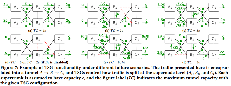
图7:不同故障场景下TSG功能示例。此处展示的流量封装为A->B->C的隧道,TSG控制流量如何在超级节点级划分(Ai,Bi和Ci)。每个超级干线的容量为C,标记TC表明给定TSG配置下的最大隧道容量。
示例:我们首先使用TSG计算的例子,用于计算某一隧道内细粒度流量工程。图7a中,到超级节点Bi的流量在两个到下一隧道站点的超级站点间均匀划分(C1和C2)。由于拓扑设计为对称超级节点级容量,图7a展示了常见场景。然而,由于数据平面故障和网络操作,容量不对称仍有可能发生。图7b展示了一种故障场景,其中B1完全失去与C1和C2的链接。为了绕过故障,B1上的TSG编排为仅转发到B2。图7c展示了B2相对于B1有两倍到C的容量的场景。其结果是,计算出的B1的TSG在下一站点(C2)和自站点(B2)间划分的比例为2:1。简化起见,下一站点C的TSG不需要重新均衡入口流量。
We calculate TSGs independently for each site-level link. For our deployments, we assume balanced incoming traffc across supernodes as we observed this assumption was rarely violated in practice. This assumption allows TSGs to be reused across all tunnels that traverse the site-level link, enables parallel TSG computations, and allows us to implement a simpler solution which can meet our switch hardware limits. We discuss two rare scenarios where our approach can lead to suboptimal TSG splits. First, Figure 7d shows a scenario where B1 loses connectivity to both next site and self site. This scenario is uncommon and has happened only once, as the sidelinks are located inside a datacenter facility and hence much more reliable than WAN links. In this case, the site-level link (B,C) is unusable. One could manually recover the site-level link capacity by disabling B1 (making all its incident links unusable), but it comes at the expense of capacity from B1 to elsewhere. Second, Figure 7e shows a scenario with two consecutive asymmetric site-level links resulting from concurrent failure. Because TSG calculation is agnostic to incoming traffic balance at site B, the tunnel capacity is reduced to 9c/4, 25% lower than the optimal splitting where B1 forwards half of its traffic toward self-site (B2) to accommodate the incoming trafc imbalance between B1 and B2, as shown in Figure 7f. Our measurements show that this failure pattern happens rarely: to only 0.47% of the adjacent site-level link pairs on average. We leave more sophisticated per-tunnel TSG generation to future work.
我们单独为站点级链路计算TSG。对于我们的部署来说,我们假设超级节点间的入口流量是均衡的;实践中,我们发现很少出现违反这一假设的情形。这一假设允许TSG在途径站点级链路的所有隧道间被重用,使得并行TSG计算成为可能,并且允许我们实现一种简单的方案满足硬件限制。我们讨论两种很少出现的场景,这些场景中我们的解决方案可能导致TSG划分不理想。首先,图7d展示了一种场景,其中B1失去子站点和下一站点的链接。这种场景并不常见,且只发生了一次,这是因为旁路在同一数据中心中,因此比WAN链路更为可靠。这种情形下,站点级链路(B,C)不可用。可以通过使B1失效(所有进入B1的链路无效)恢复站点级链路的容量,但这种方法的代价是B1到其他地方的容量不可用。第二,图7e显示了并发故障导致的两个连续不对称站点级链路的情景。由于站点B处入口流量均衡对TSG计算是不可知的,隧道容量降低到9c/4,比理想划分降低了25%(B1转发其一半的流量到自站点B2以适应B1和B2间入口流量的不均衡,如图7f所示)。我们的测试表明这种故障模式极少发生:平均只有0.47%的链接站点级链路对。我们将更精致的每隧道TSG生成留作未来工作。
TSG generation algorithm: We model the TSG calculation as an independent network flow problem for each directed site-level link. We frst generate a graph GTSG where vertices include the supernodes in the source site of the site-level link (Si, 1 ≤ i ≤ N) and the destination site of the site-level link (D). We then add two types of links to the graph. First, we form a full mesh among the supernodes in the source site: (∀i, j 不等于 i : Si ↔ Sj). Second, links are added between each supernode in the source site and the destination site: (∀i : Si ↔ D). We associate the aggregate capacity of the corresponding supertrunks to each link. Subsequently, we generate flows with infnite demand from each supernode Si toward the target site D and try to satisfy this demand by using two kinds of pathing groups (PG) with one hop and two hop paths respectively. We use a greedy exhaustive waterfill algorithm to iteratively allocate bottleneck capacity in a max-min fair manner. We present the TSG generation pseudo code in Algorithm 1.
TSG生成算法:我们将TSG计算建模为每条直连站点级链路的网络流问题。首先,生成图GTSG,图中顶点包含站点级链路的源站点的超级节点(Si,1<=i<=N)和站点级链路的目的站点(D)。我们增加两种类型的链路到图中。首先,我们将源站点中所有超级节点构成全mesh(∀i, j 不等于 i : Si ↔ Sj)。第二,增加每个源站点的超级节点和目的站点的链接:(∀i : Si ↔ D)。我们将相应超级干线容量关联到每条链路。随后,我们生成由每个超级节点i到目的站点D的具有无限需求的数据流,并尝试使用两种选路组(PG)满足这一需求。两种选路组分别为单跳路径和2跳路径。我们使用贪心的穷举瀑布算法以最大-最小公平方式迭代的分配瓶颈容量。TSG生成算法的伪代码如算法1所示。
Theorem 4.1. The generated TSGs do not form any loop.
定理4.1:生成的TSG不会形成环路。
Proof. Assume the generated graph has K + 1 vertices: Si (0 ≤ i ≤ K - 1), each represents a supernode in the source site, and D represents the destination site. Given the pathing constraint imposed in step (1), each flow can only use either the one-hop direct path (Si→D) or two-hop paths (Si→Sj,i→D), while the one-hop direct path is strictly preferred over two-hop paths. Assume a loop with ℓ > 1 hops are formed with forwarding sequence, without loss of generality: <S0, S1, ..., Sℓ-1, S0>. Note that the loop cannot contain destination vertex D. Given the pathing preference and the loop sequence, the link (Si , D) must be bottlenecked prior to (Si+1, D), and (Sℓ-1, D) must be bottlenecked prior to (S0, D). We observe that bottleneck sequences form a loop, which is impossible given that the algorithm only bottlenecks each link once.
证明. 假设生成图中有K+1个顶点:Si(0 ≤ i ≤ K - 1)表示源站点中的超级节点,和表示目的站点的D。给定步骤(1)中施加的选路限制,每条流智能使用单跳直连链路 (Si→D) 或两跳路径 (Si→Sj不等于i→D),且单跳路径严格优先于两跳路径。假设ℓ > 1跳的环路在转发序列中形成,不失一般性,假设环路为<S0, S1, ..., Sℓ-1, S0>。注意到环路中不能包含目的顶点D。考虑到选路优先和环路序列,链路 (Si , D) 在 (Si+1, D)前成为瓶颈,且(Sℓ-1, D)在(S0, D)前成为瓶颈。我们发现这种瓶颈序列形成环路,考虑到算法中每条链路只成为瓶颈一次,上述序列是不可能的。
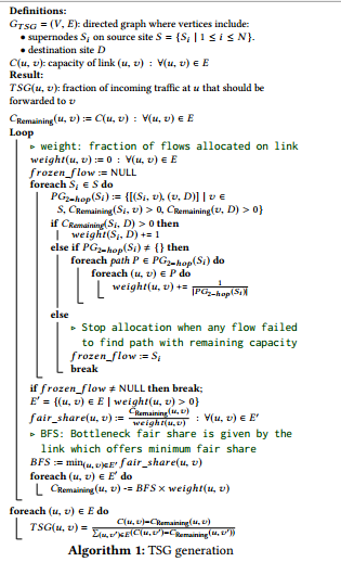
算法1: TSG生成
4.4 Sequencing TSG Updates (编排TSG更新顺序)
We fnd that applying TSG updates in an arbitrary order could cause transient yet severe traffic looping/blackholing (§6.3), reducing availability. Hence, we develop a scalable algorithm to sequence TSG updates in a provably blackhole/loop-free manner as follows.
我们发现以任意顺序进行TSG更新会导致瞬时但严重的流量环路/黑洞(6.3节),降低可用性。为此,我们开发了编排TSG更新顺序的可扩展算法,使得更新是无黑洞/环路的,描述如下。
TSG sequencing algorithm: Given the graph GTSG and the result of the TSGs described in §4.3, we create a dependency graph as follows. First, vertices in the dependency graph are the same as that in GTSG. We add a directed link from Si to Sj if Sj appears in the set of next hops for Si in the target TSG confguration. An additional directed link from Si to D is added if Si forwards any traffic directly to the next-site in the target TSG confguration. According to Theorem 4.1, this dependency graph will not contain a loop and is therefore a directed acyclic graph (DAG) with an existing topological ordering. We apply TSG updates to each supernode in the reverse topological ordering, and we show that the algorithm does not cause any transient loops or blackholes during transition as follows. Note that this dependency based TSG sequencing is similar to how certain events are handled in Interior Gateway Protocol (IGP), such as link down, metric change [11] and migrations [33].
TSG序列化算法:给定图GTSG和4.3节描述的TSG结果,我们按如下方式构造依赖图。首先,依赖图中的顶点和图GTSG中一样。如果Sj出现在目标TSG配置中Si的下一跳集合中,增加直连链路Si->Sj。如果Si直接转发任意流量到目标TSG配置中的下一跳,则增加Si到D的直连链路。根据定理4.1,依赖图中不包含环路,因此是具有当前拓扑序的有向无环图(DAG)。我们以逆拓扑序应用每个超级节点的TSG更新;在如下转变期间,该算法不会导致瞬时环路或黑洞。注意,基于依赖的TSG序列和内部网关协议中(IGP)特定时间如何处理类似,如链路断掉、度量值改变[11]和迁移[33]。
Theorem 4.2. Assuming that neither the original nor the target TSG confguration contains a loop, none of the intermediate TSG confgurations contains a loop.
定理4.2. 假设原始或目标TSG配置中均不含环路,那么中间TSG配置也不会包含环路。
Proof. At any intermediate step, each vertex can be considered either resolved, in which the represented supernode forwards traffic using the target TSG, or unresolved, in which the traffic is forwarded using the original TSG. The vertex D is always considered resolved. We observe that the loop cannot be formed among resolved vertices, because the target TSG confguration does not contain a loop. Similarly, a loop cannot be formed among unresolved vertices, since the original TSG confguration is loop-free. Therefore, a loop can only be formed if it consists of at least one resolved vertex and at least one unresolved vertex. Thus, the loop must contain at least one link from a resolved vertex to an unresolved vertex. However, since the vertices are updated in the reverse topological ordering of the dependency graph, it is impossible for a resolved vertex to forward traffic to an unresolved vertex, and therefore a loop cannot be formed.
证明:在任意中间步骤,每个顶点可以认为是已决断的(超级节点使用目标TSG转发流)或者未决断的(超级解决使用原始TSG转发流)。顶点D总是已决断的。我们发现环路不会在已决断顶点间形成,这是因为目标TSG配置不包含环路。类似地,环路也不能在未决断顶点间形成,因为原始的TSG配置是无环的。因此,环路必须要包含至少一个已决断顶点和至少一个未决断顶点。然而,由于顶点以依赖图的逆拓扑序更新,已决断顶点不可能转发流到未决断顶点,因此无法形成环路。
Theorem 4.3. Consider a flow to be blackholing if it crosses a down link using a given TSG confguration. Assuming that the original TSG confguration may contain blackholing flows, the target TSG confguration is blackhole-free, and the set of down links is unchanged, none of the intermediate TSG confgurations causes a flow to blackhole if it was not blackholing in the original TSG confguration.
定理4.3. 给定TSG配置,如果某流途径失效链路那么该留认为具有黑洞。假设原始TSG配置可能包含黑洞流,目标TSG配置没有黑洞,并且是失效链路未发生变化,那么如果流在原始TSG配置中没有黑洞,那么在任何中间TSG配置中也不会具有黑洞。
Proof. See the defnition of resolved/unresolved vertex in the proof of Theorem 4.2. Assume a flow Si → D is blackholing at an intermediate step during the transition from the original to the target TSG. Assume that this flow was not blackholing in the original TSG. Therefore, at least one transit vertex for this flow must have been resolved, and the blackhole must happen on or after the frst resolved vertex. However, since the resolved vertices do not forward traffic back to unresolved vertices, the backhole can only happen in resolved vertices, which contradicts our assumption.
证明:参见定理4.2证明中已决断和未决断顶点的定义。假设流Si->D在由原始TSG到目标TSG转变的中间步骤中具有黑洞。假设该流在原始TSG中不具有黑洞。那么,该留的至少一个中转顶点是已决断的,且黑洞发生在第一个已决断顶点或其后。然而,由于已决断顶点不会转发流回到未决断顶点,黑洞只能出现在已决断顶点,与我们的假设相悖。
5 EFFICIENT SWITCH RULE MANAGEMENT (高效交换机规则管理)
Off-the-shelf switch chips impose hard limits on the size of each table. In this section, we show that FG matching and traffic hashing are two key drivers pushing us against the limits of switch forwarding rules to meet our availability and scalability goals. To overcome these limits, we partition our FG matching rules into two switch pipeline tables to support 60x more sites (§5.1). We further decouple the hierarchical TE splits into two-stage hashing across the switches in our two-stage Clos supernode (§5.2). Without this optimization, we find that our hierarchical TE would lose 6% throughput as a result of coarser traffic splits.
商用交换芯片具有严格的表大小限制。本节,我们指出FG匹配和流哈希是推动我们打破交换机转发规则限制以满足可用性和可扩展性目标的关键驱动力。为了解决这些限制,我们将FG匹配规则划分到两个交换机流水表以支持60倍数量的站点(5.1节)。我们进一步解耦层次化TE划分到跨2阶段Clos超级节点交换机的2阶段哈希计算(5.2节)。没有上述优化方案的情形下,我们发现层次化TE将损失6%的吞吐量,因为粗粒度流划分。
5.1 Hierarchical FG Matching (层次化FG匹配)
We initially implemented FG matching using Access Control List (ACL) tables to leverage their generic wildcard matching capability. The number of FG match entries was bounded by the ACL table size:
最初,我们采用访问控制列表(ACL)表实现FG匹配,以利用他们的通配能力。FG匹配项的数量受限于ACL表大小:
sizeACL ≥ numSites × numPrefixes/Site × numServiceClasses
given the ACL table size limit (sizeACL = 3K), the number of supported service classes (numServiceClasses = 6, see Table 1) and the average number of aggregate IPv4 and IPv6 cluster prefxes per site (numPrefixes/Site ≥ 16), we anticipated hitting the ACL table limit with ∼ 32 sites.
给定ACL表大小限制(sizeACL = 3K),支持的服务等级数量(参见表1,numServiceClasses = 6)和每站点平均聚合IPv4和IPv6集群前缀(numPrefixes/Site ≥ 16),在有约32个站点时,达到ACL表限制。
Hence, we partition FG matching into two hierarchical stages, as shown in Figure 8b. We frst move the cluster prefix matches to Longest Prefx Match (LPM) table, which is much larger than the ACL table, storing up to several hundreds of thousands of entries. Even though the LPM entries cannot directly match DSCP bits for service class support, LPM entries can match against Virtual Routing Forwarding (VRF) label. Therefore, we match DSCP bits via the Virtual Forwarding Plane (VFP) table, which allows the matched packets to be associated with a VRF label to represent its service class before entering the LPM table in switch pipeline. We fnd this two-stage, scalable approach can support up to 1,920 sites.

图8:解耦FG匹配为两个阶段。
因此,我们将FG匹配划分为两个层次化阶段,如图8b所示。我们首先将集群前缀匹配移动到最长前缀匹配(LPM)表,该表比ACL表大得多,可以存储多达几十万表项。尽管LPM表项无法直接匹配DSCP比特以支持服务等级,LPM表项可以匹配虚拟路由转发(VRF)标签。因此,我们通过虚拟转发平面(VFP)表匹配DSCP标记,使得匹配的数据包在进入交换机流水线的LPM表之前可以关联一个VRF标签标示其相应的服务等级。我们发现这种2阶段可扩展的方法可以支持多达1920个站点。
This optimization also enables other useful features. We run TE as the primary routing stack and BGP/ISIS routing as a backup. In face of critical TE issues, we can disable TE at the source sites by temporarily falling back to BGP/ISIS routing. This means that we delete the TE forwarding rules at the switches in the ingress sites, so that the packets can fallback to match lower-priority BGP/ISIS forwarding rules without encapsulation. However, disabling TE end-to-end only for traffic between a single source-destination pair is more challenging, as we must also match cluster-facing ingress ports. Otherwise, even though the source site will not encapsulate packets, unencapsulated packets can follow the BGP/ISIS routes and later be incorrectly encapsulated at transit site where TE is still enabled towards the given destination. Adding ingress port matching was only feasible with the scalable, two-stage FG match.
这种优化还可以使能其他有用的特征。我们以TE作为主要的路由栈,BGP/ISIS路由作为备份。面对关键TE问题时,我们可以在源站点断掉TE临时回滚到BGP/ISIS路由。这表明在入口站点我们删除交换机中TE转发规则,这样数据包可以回滚回匹配低优先级BGP/ISIS转发规则的方式,而不需要封装。然而,仅使单一源-目的对(端到端)之间的流的TE失效是具有挑战的,因为我们必须匹配面向集群的入口端口。否则,即使源站点不封装数据包,为封装的数据包可以随着BGP/ISIS路由,随后在中转站点(到给定目标的TE仍然有效)被不正确的封装。增加入口端口匹配只有在使用可扩展的两阶段FG匹配时才可行。
5.2 Efficient Traffic Hashing By Partitioning (使用划分的高效流哈希)
With hierarchical TE, the source site is responsible for implementing TG, TSG and SSG splits. In the original design, we collapsed the hierarchical splits and implemented them on only ingress edge switches. However, we anticipated approaching the hard limits on switch ECMP table size:
使用层次化TE,源站点负责实现TG、TSG和SSG划分。原始设计中,我们折叠层次划分,并仅在入口边交换机实现。然而,我们预计这会接近交换机ECMP表大小的硬限制:
sizeECMP ≥ numSites × numPathingClasses × numTGs × numTSGs × numSSGs
where numPathingClasses = 3 is the number of aggregated service classes which share common pathing constraints, numTGs = 4 is the tunnel split granularity, numTSGs = 32 is the per-supernode split granularity, and numSSGs = 16 splits across 16 switches in Stargate backend stage. To support up to 33 sites, we would need 198K ECMP entries while our switches support up to only sizeECMP = 14K entries, after excluding 2K BGP/ISIS entries. We could down-quantize the traffic splits to avoid hitting the table limit. However, we find the benefit of TE would decline sharply due to the poor granularity of traffic split.
这里,numPathingClasses = 3表示聚合服务等级的数量(共享相同的选路限制),numTGs = 4表示隧道划分粒度,numTSGs = 32表示每超级节点划分粒度,and numSSGs = 16在Stargate后端阶段跨交换机划分。为了支持33个站点,需要198K ECMP表项,然而在排除2K BGP/ISIS表项后我们的交换机只支持 sizeECMP = 14K表项,我们下量化流划分以避免达到表限制。然而,我们发现TE的优势将急剧下降,因为较差的流划分粒度。
We overcome per-switch table limitations by decoupling traffic splitting rules across two levels in the Clos fabric, as shown in Table 3. First, the edge switches decide which tunnel to use (TG split) and which site the ingress traffic should be forwarded to (TSG split part 1). To propagate the decision to the backend switches, we encapsulate packets into an IP address used to specify the selected tunnel (TG split) and mark with a special source MAC address used to represent the self-/next-site target (TSG split part 1). Based on the tunnel IP address and source MAC address, backend switches decide the peer supernode the packet should be forwarded to (TSG split part 2) and the egress edge switch which has connectivity toward the target supernode (SSG split). To further reduce the required splitting rules on ingress switches, we confgured a link aggregation group (LAG) for each edge switch toward viable backend switches. For simplicity, we consider a backend switch is viable if the switch itself is active and has active connections to every edge switch in the supernode.
我们通过接口流划分规则到跨两级Clos设施克服每交换机限制(如表3所示)。首先,边缘交换机决定使用哪个隧道(TG划分)以及入口流应该转发到哪个站点(TSG划分第一部分)。为了把决定传播到后端交换机,我们将数据封装到用于指定选定隧道的IP地址(TG划分)并且使用特定的MAC地址用来表示自站点/下一站点目标(TSG划分部分1)。基于隧道IP和源MAC地址,后端交换机决定数据包应该转发到的对等超级节点(TSG划分部分2)以及与目标超级节点具有连接的出口边缘交换机(SSG划分)。为了进一步降低入口交换机上的划分规则,我们为每个边缘交换机到可见后端交换机配置了链路聚合组(LAG)。为了简化起见,我们认为后端交换机是可见的,如果该交换机自身是有效的并且到超级节点中的每个边缘交换机具有有效连接。
6 EVALUATION (评估)
In this section, we present our evaluation of the evolved B4 network. We fnd that our approaches successfully scale B4 to accommodate 100x more traffic in the past five years (§6.1) while concurrently satisfying our stringent availability targets in every service class (§6.2). We also evaluate our design choices, including the use of sidelinks in hierarchical topology, hierarchical TE architecture, and the two-stage hashing mechanism (§6.3) to understand their tradeoffs in achieving our requirements.
本节,我们评估演进的B4网络。我们发现,在过去5年,我们的方法使得B4成功的扩展到应用100倍流量(6.1节),同时满足严格的每个服务等级的可用性目标(6.2节)。我们评估了设计选择,包括层次化拓扑中旁路的应用,层次化TE架构和两阶段哈希机制(6.3节),用于理解取得我们要求的权衡。
6.1 Scale (扩展性)
Figure 9 demonstrates that B4 has signifcant growth across multiple dimensions. In particular, aggregate B4 traffic was increased by two orders of magnitude in the last fve years, as shown in Figure 9a. On average, B4 traffic has doubled every nine months since its inception. B4 has been delivering more traffic and growing faster than our Internet-facing WAN. A key growth driver is that Stargate subsumed the campus aggregation network (§3.2) and started offering huge amounts of campus bandwidth in 2015.
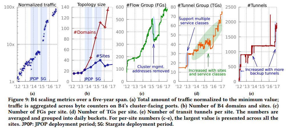
图9:B4在5年内的规模扩展度量。(a)总流量;B4面向集群的端口的字节计数总量。(b)B4域和站点的数量。(c)每站点FG数量。(d)每站点TG数量。(e)每站点中转隧道数量。
图9表明B4在多个维度取得长足的发展。具体地,B4聚合流量在过去的5年增长了2个量级,如图9a所示。平均来讲,B4流量每9个月翻一番。B4正在传输比面向因特网的WAN更多的流量且增长速度更快。关键的增长驱动是Stargate纳入了园区聚合网络(3.2节),并且自2015年开始提供大量的园区带宽。
Figure 9b shows the growth of B4 topology size as the number of sites and control domains. These two numbers matched in Saturn-based B4 (single control domain per site) and have started diverging since the deployment of JPOP fabrics in 2013. To address scalability challenges, we considerably reduced the site count by deprecating Saturn fabrics with Stargate in 2015. Ironically, this presented scaling challenges during the migration period because both Saturn and Stargate fabrics temporarily co-existed at a site.
图9b给出B4拓扑大小的增长,以站点数量和控制域数量计。在基于Saturn的B4中(每站点一个控制域),这两个数字相同,并在2013年开始分离,这是因为JPOP开始部署。为了解决扩展性挑战,自2015年通过使用Stargate替代Saturn,我们极大的降低了站点数量。讽刺的是,这里给出迁移期间扩展性挑战,这一期间Saturn和Stargate在同一站点共存
Figure 9c shows the number of FGs per source site has increased by 6x in the last fve years. In 2015, we stopped distributing management IP addresses for switch and supertrunk interfaces. These IP addresses cannot be aggregated with cluster prefxes, and removing these addresses helped reduce the number of FGs per site by ∼ 30%.
图9c给出每个源站点的FG数量在过去5年增长了6倍。2015年,我们停止为交换机和超级干线端口分发管理IP地址。这些IP地址无法聚合为集群前缀,移除这些地址帮助将每个站点的FG数量减少约30%。
B4 supports per service class tunneling. The initial feature was rolled out with two service classes in the beginning of 2013 and resulted in doubling the total number of TGs per site as shown in Figure 9d. After that, the TG count continues to grow with newly deployed sites and more service classes.
B4支持每服务等级隧道。2013开始,最初是使用两个服务等级,结果是导致每站点TG数量翻番,如图9d所示。随后,TG数量技术随着新部署站点和更多服务等级增长。
The maximum number of transit tunnels per site is controlled by the central controller’s confguration. This constraint helps avoid installing more switch rules than available but also limits the number of backup tunnels which are needed for fast blackhole recovery upon data plane failure. In 2016, improvements to switch rule management enabled us to install more backup tunnels and improve availability against unplanned node/link failure.
每站点最大中转隧道数量由集中控制器配置控制。这一约束帮助我们避免安装比可用规则更多的交换机规则,也限制了备份隧道的数量(对于数据平面故障的快速黑洞恢复是必须的)。2016年,交换机规则管理的提升使我们能够安装更多的备份隧道,并提升非计划节点/链路故障时的可用性。
6.2 Availability (可用性)
We measure B4 availability at the granularity of FG via two methodologies combined together:
我们以FG的粒度度量B4的可用性,这一度量通过结合两个方法:
Bandwidth-based availability is defned as the bandwidth fulfllment ratio given by Google Bandwidth Enforcer [25]:
基于带宽的可用性:定义为谷歌带宽实施者[25]给定的带宽满足率:
allocation
------------------------------
min{demand, approval}
where demand is estimated based on short-term historical usage, approval is the approved minimum bandwidth per SLO contract, and allocation is the current bandwidth admitted by bandwidth enforcement, subject to network capacity and fairness constraints. This metric alone is insufcient because of bandwidth enforcement reaction delay and the inaccuracy of bandwidth estimation (e.g., due to TCP backoff during congestion).
这里,需求基于短期历史使用量度量,批准指每SLO合约许可的最小带宽,分配是当前准入带宽(受限于网络容量和公平性约束)。该度量是不充分的,因为带宽实施响应延迟和带宽评估的不准去性(如,由于拥塞期间的TCP回退)。
Connectivity-based availability complements the limitations of bandwidth fulfllment. A network measurement system is used to proactively send probes between all cluster pairs in each service class. The probing results are grouped into B4 site pairs using 1-minute buckets, and the availability for each bucket is derived as follows:
基于链接的可用性作为带宽满足限制的互补。网络度量系统用于主动在所有集群对间的每个服务等级发送探测。探测结果按B4站点对分组,并使用1-分钟桶,每个桶的可用性按如下计算:
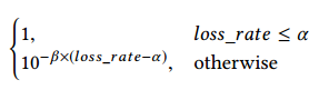
where α = 5% is a sensitivity threshold which filters out most of the transient losses while capturing the bigger loss events which affect our availability budget. Beyond the threshold, availability decreases exponentially with a decay factor β = 2% as the traffic loss rate increases. The rationale is that most inter-datacenter services run in a parallel worker model where blackholing the transmission of any worker can disproportionately affect service completion time.
这里α = 5%为敏感阈值,滤除大部分瞬时丢失,并捕获影响可用性的大的丢失事件。阈值之上,可用性随着流量丢失率的增加以衰减因子β = 2%指数级减少。合理性解释是大部分数据中心间服务运行于并行工作者模式,任何工作者的黑洞传输可以不成比例的影响服务完成时间。
Availability is calculated by taking the minimum between these two metrics. Figure 10 compares the measured and target availability in each service class. We see that initially B4 achieved lower than three nines of availability at 90th percentile flow across several service classes. At this time, B4 was not qualified to deliver SC3/SC4 traffic other than probing packets used for availability measurement. However, we see a clear improvement trend in the latest state: 4- 7x in SC1/SC2 and 10-19x in SC3/SC4. As a result, B4 successfully
achieves our availability targets in every service class.
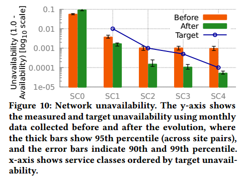
图10:网络不可达性。y轴给出测量的和目标不可用性(使用演化前后每月数据),这里粗条表示95th百分比(站点对间),误差条表示90th和99th百分比。x轴给出按目标不可用性排序的服务等级。
可用性通过这两个度量值的较小者计算。图10比较了每个服务等级的测量的可用性和目标可用性。我们发现B4最开始在多个服务等级的90th百分比的流取得低于三个九的可用性。那时,B4不适用于传输SC3/SC4流量(除了用于可用性测量的探测包)。然而,我们见证了清晰的提升趋势:SC1/SC2的4-7倍提升和SC3/SC4的10-19倍提升。其结果是,B4的每个服务等级都可以取得我们的可用性目标。
6.3 Design Tradeoffs (设计权衡)
Topology abstraction: Figure 11 demonstrates the importance of sidelinks in hierarchical topology. Without sidelinks, the central controller relies on ECMP to uniformly split traffic across supernodes toward the next site in the tunnel. With sidelinks, the central controller uses TSGs to minimize the impact of capacity loss due to hierarchical topology by rebalancing traffic across sidelinks to match the asymmetric connectivity between supernodes. In the median case, abstract capacity loss reduces from 3.2% (without sidelinks) to 0.6% (with sidelinks+TSG). Moreover, we observe that the abstract capacity loss without sidelinks is 100% at 83-rd percentile because at least one supernode has lost connectivity toward the next site. Under such failure scenarios, the vast majority of capacity loss can be effectively alleviated with sidelinks.
图11:层次化拓扑中容量不对称导致的容量损失。
拓扑:图11展示层次化拓扑中旁路的重要性。没有旁路时,集中控制器依赖于ECMP以在多个通向隧道中下一站点的超级节点间均匀划分流量。使用旁路,集中控制器使用TSG最小化容量损失(由于层次化拓扑)的影响(通过重新均衡流量以匹配超级节点间的不对称连通)。平均情形下,抽象容量损失由3.2%(没有旁路)减少到0.6%(使用旁路和TSG)。此外,我们发现不使用旁路在83rd百分比时容量损失达100%,这是因为至少一个超级节点失去到下一站点的连通。在这种故障情景,使用旁路可以有效避免大部分容量损失。
Hierarchical TE with two-stage hashing: Figure 12 quantifies the tradeoff between throughput and runtime as a function of TE algorithm and traffic split granularity. We compare our new hierarchical TE approach with flat TE, which directly runs a TE optimization algorithm (§4.3 in [18]) on the supernode-level topology. To evaluate TE-delivered capacity subject to the trafic split granularity limit, we linearly scale the traffic usage of each FG measured in Jan 2018, feed the adjusted traffic usage as demand to both flat and hierarchical TE, and then feed the demands, topology and TE pathing to a bandwidth allocation algorithm (see §5 in [25]) for deriving the maximum achievable throughput based on the max-min fair demand allocations.
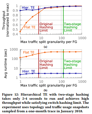
图12:使用两阶段哈希的层次化TE运行时间为2-4秒,取得较高的吞吐量且满足交换机哈希限制。
2阶段哈希的层次化TE:图12量化吞吐量和运行时间的权衡(作为TE算法和流量划分粒度的函数)。我们比较了新的层次化TE方法和扁平TE(直接在超级节点级拓扑上运行TE优化算法,参见[18]中4.3节)。为了评估受限于划分粒度限制的TE容量,我们线性扩展每个FG流量使用量(2018年1月测量),将调整后的流量使用量作为需求灌输到扁平和层次化TE,接着将需求、拓扑和TE选路灌输到带宽分配算法([25]中第5部分)以获得基于最大-最小公平需求分配的最大可得吞吐量。
We make several observations from these results. First, we find that hierarchical TE takes only 2-3 seconds to run, 188 times faster than flat TE. TSG generation runtime is consistently a small fraction of the overall runtime, ranging from 200 to 700 milliseconds. Second, when the maximum traffic split granularity is set to 1, both hierarchical and flat TE perform poorly, achieving less than 91% and 46% of their maximum throughput. The reason is simple: Each FG can only take the shortest available path, and the lack of sufficient path diversity leaves many links under-utilized, especially for flat TE as we have exponentially more links in the supernode-level graph. Third, we see that with our original 8-way traffic splitting, hierarchical TE achieves only 94% of its maximum throughput. By moving to two-stage hashing, we come close to maximal throughput via 128-way TG and TSG split granularity while satisfying switch hashing limits.
我们由上述结果中得出如下结论。首先,我们发现层次化TE的运行时间为2-3秒,比扁平化TE快188倍。TSG生成运行时间是总运行时间的一小部分,从200到700毫秒。第二,当最大流划分粒度设置为1时,层次化和扁平TE性能较差,取得少于91%和46%的最大吞吐量。原因很简单:每个FG只能使用最短可用路径,且充分路径多样性的缺失导致很多链路无法充分使用,特别是对扁平拓扑(因为在超级节点级图中有指数级数量更多的链路)。第三,我们发现使用原始的8-路流划分,层次化TE取得94%的最大吞吐量。通过采用两阶段哈希,我们使用128-路TG和TSG划分粒度达到接近最大化吞吐量,并且满足交换机哈希限制。
TSG sequencing: We evaluate the tradeoffs with and without TSG sequencing using a one-month trace. In this experiment, we exclude 17% of TSG ops which update only one supernode. Figure 13a shows that TSG sequencing takes only one or two “steps” in > 99.7% of the TSG ops. Each step consists of one or multiple TSG updates where their relative order is not enforced. Figure 13b compares the end-to-end latency of TSG ops with and without sequencing. We observe a 2x latency increase at 99.7th percentile, while the worst case increase is 2.63x. Moreover, we find that the runtime of the TSG sequencing algorithm is negligible relative to the programming latency. Figure 13c shows the capacity available at each intermediate state during TSG ops. Without TSG sequencing, available capacity drops to zero due to blackholing/looping in ∼ 3% of the cases, while this number is improved by an order of magnitude with sequencing. Figure 13d demonstrates that without sequencing, more than 38% of the ingress traffic would be discarded due to the forwarding loop formed in > 2% of the intermediate states during TSG ops.
TSG顺序:我们使用一个月的trace评估使用和不使用TSG序列的权衡。实验中,我们排除17%的只更新一个超级节点的TSG操作。图13a显示只采用1步或2步的TSG序列多达TSG操作的99.7%。每个步骤只有一个或多个TSG更新(其相对顺序没有规定)。图13b比较使用和不使用序列化时TSG操作的端到端延迟。我们发现99.7th百分比时2倍的延迟增长,最坏情形下有2.63倍的延迟增长。此外,我们发现TSG序列算法的运行时间与程序延迟负相关。图13c给出TSG操作期间每个中间状态的可用容量。不使用TSG序列化,由于3%情形下的黑洞/环路,可用容量降至0,使用序列化时该数字提升了一个数量级。图13d表明不使用序列化,多达38%的入口流量因大于2%的中间状态形成环路而丢失。
7 OPERATIONAL EXPERIENCE AND OPEN PROBLEMS (运维经验和开放问题)
In this section, we summarize our experiences learned from production B4 network as well as several open problems that remain active areas of work.
本节,我们总结生产环境中B4网络的经验教训和一些仍然活跃的开放问题。
Management workflow simplifcation: Before the evolution, we rely on ECMP to uniformly load-balance traffic across Saturn chassis at each stage (§3.1), and therefore the traffic is typically bottlenecked by the chassis which has the least amount of outgoing capacity. In this design, the admissible capacity of a Saturn site drops signifcantly in the presence of capacity asymmetry resulting from failure or disruptive network operation. Consequently, we had to manually account for the capacity loss due to capacity asymmetry for disruptive network operations in order to ensure the degraded site capacity still meets the traffic demand requirements. Jumpgate’s improved handling of asymmetry using sidelinks and TSGs has reduced the need for manual interaction, as the TE system can automatically use the asymmetric capacity effectively.
管理工作流简化:演化前,我们依赖ECMP在Saturn底板的每个阶段均衡数据流(节3.1),因此,数据流受限于具有最小出口容量的瓶颈底板。设计中,当故障或网络操作导致的容量不对称存在时,Saturn的准入流量显著降低。因此,我们需要人为考虑容量不对称导致的容量损失以保证降低的站点容量仍然满足流量需求。Jumpgate采用旁路和TSG提高不对称处理,减少了人工干预需求,这是因为TE系统可以自动高效使用不对称容量。
By virtue of Jumpgate’s multiple independent control domains per site (§3.2), we now restrict operations to modify one domain at a time to limit potential impact. To assess a change’s impact on network availability, we perform impact analysis accounting for the projected capacity change, potential network failures, and other maintenance coinciding with the time window of network operation. We tightly couple our software controller with the impact analysis tool to accurately account for potential abstraction capacity loss due to disruptive network operations. Depending on the results, a network operation request can be approved or rejected.
凭借Jumpgate每站点多个独立控制域(节3.2),我们限制操作只能每次修改一个域以限制可能的影响。为了评估改变对网络可用性的影响,我们以预测的容量改变、可能的网络故障和其他网络操作窗口内的维护来执行影响分析。我们将软件控制器和影响分析工具紧耦合以精确核算可能的容量损失(打断性网络操作导致)。基于这些结果,网络操作可能被许可或拒绝。
To minimize potential impact on availability, we develop a mechanism called “drain” to shift traffic away from certain network entities before a disruptive change in a safe manner which prevents traffic loss. With the scale of B4, it is impractical for network operators and Site Reliability Engineers to use command-line interface (CLI) to manage each domain controller. Consequently, drain operations are invoked by management tools which orchestrate network operations through management RPCs exposed by the controllers.
为了最小化可用性影响,我们开发了称为“drain”的机制在中断性改变发生前安全地将流量转移出特定的网络实体,以防止流丢失。在B4的规模下,网络操作者和站点可靠性工程师不太可能使用命令行接口(CLI)管理每个域控制器。因此,drain操作由管理工具调用;管理工具通过控制器暴露的管理RPC编排网络操作。
Sidelink capacity planning: Sidelinks form a full mesh topology among supernodes to account for WAN capacity asymmetry caused by physical failure, network operation, and striping inefficiency. Up to 16% of B4 site capacity is dedicated to sidelinks to ensure that our TSG algorithm can fully utilize WAN capacity against common failure patterns. However, determining the optimal sidelink capacity that should be deployed to meet bandwidth guarantees is a hard provisioning problem that relies on long-term demand forecasting, cost estimates and business case analysis [5]. We are actively working on a log-driven statistical analysis framework that will allow us to plan sidelink capacity while minimizing costs in order to meet our network availability requirements.
旁路容量规划:旁路在超级节点间形成mesh拓扑,应对物理故障、网络操作和划分不充分导致的WAN容量不对称。多达16%的B4站点容量指定给旁路,保证TSG算法可以充分利用WAN容量。然而,确定最优的旁路容量(满足带宽保证)是困难的供应问题,依赖于长期需求预测、成本评估和商业案例分析[5]。我们正在积极开发日志驱动的统计分析框架使得我们可以规划旁路的容量,同时最小化成本以满足网络可用性需求。
Imbalance ingress traffic handling: Our TSG algorithm assumes balanced incoming traffic across supernodes in a site (§4.3). This assumption simplifes our design and more importantly, it allows us to meet our switch hardware requirements at scale—Tunnels that shared the same site-level link use a common set of TSG rules programmed in switch forwarding tables. Comparing with per-tunnel TSG allocation, which requires > 1K TSG rules and exceeds our hardware rule limit, our TSG algorithm requires up to N TSG rules, where N ≈ 6 is the number of peering site. However, it does not handle imbalance of ingress traffic. We plan to study alternative designs such as computing TSGs for each pair of adjacent site-level links. This design will handle ingress traffic imbalance based on capacity asymmetry observed in the upstream site-level link, while requiring a slightly higher number of TSG rules (N(N - 1) = 30) in switch hardware.
不均衡入口流哈希:TSG算法假设站点内超级节点间的输入流量是均衡的(4.3节)。这一假设简化了我们的设计,更重要的是,这允许我们满足一定规模下的交换机硬件需求(共享相同站点链路的隧道使用相同的TSG规则集合,这些集合编程到交换机转发表)。与每隧道TSG分配相比(要求>1K TSG规则,超过硬件规则限制),TSG算法需要多大N TSG规则,这里N ≈ 6指对等站点的数量。然而,它并不处理入口流的不均衡。我们计划研究可选设计,例如为每对相邻站点级链路计算TSG。这一设计将处理基于容量不对称的入口流量不对称(上游站点级链路中观察到),同时交换机硬件中需要稍多数量的TSG规则(N(N - 1) = 30) 。