芯片的pin 脚可以用作不同的功能,最常用的是作为GPIO,设置为输出模式时,通过高低电平来控制一些外围设置;
// 如LED,屏的电源,背光的开关,功放的静音等等。 除了控制设置之外,还需要和外部设置传输数据。
pin 作为GPIO 设置为IN时,是获取外设的高低来判断外设的状态,最常用的一些source 通道的detect,及一些wakeup 功能。
pin 作为SAR 口,获取ADC值; // 如按键板,参照“mstar平台SAR口使用”
pin 作为UART / SPI /SD 口;
pin 作为I2C 口;
一般来说,大部分有特殊功能的Pin脚其实都可以作为GPIO使用,当将其配置成特殊功能后,就不能同时配为GPIO。所以当发现某个Pin配成GPIO后,却没办法改变它的高低状态时,就要留意一下该Pin脚是否已经被误配为特殊功能了,这时就需要先DISABLE 掉这个特殊功能之后,才能设置成GPIO及其状态设定。每个chip有对应一个init GPIO配置,BD_MST{$Board}.h, drvpadconf.c
1、标准GPIO口配置
总共有4种状态:
#define GPIO_NONE                   0       // Not GPIO pin (default)
#define GPIO_IN                     1       // GPI
#define GPIO_OUT_LOW                2       // GPO output low
#define GPIO_OUT_HIGH               3       // GPO output high
2、特殊口配置
(1)uart 口配置,特殊功能的pin需要在BD_MST{$Board}.h 中配置,如:BD_MST160D_10ABQM_M7221.h
#define DISABLE                         0
#define ENABLE                          1

#define CONFIG_PADMUX_MODE0                     0x00
#define CONFIG_PADMUX_MODE1                     0x01
#define CONFIG_PADMUX_MODE2                     0x02
#define CONFIG_PADMUX_MODE3                     0x03
#define CONFIG_PADMUX_MODE4                     0x04
#define CONFIG_PADMUX_MODE5                     0x05
#define CONFIG_PADMUX_MODE6                     0x06
#define CONFIG_PADMUX_MODE7                     0x07
#define CONFIG_PADMUX_MODE8                     0x08
#define CONFIG_PADMUX_MODE9                     0x09
#define CONFIG_PADMUX_UNKNOWN                   0xFF
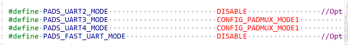
例如UART3,UART4 配置成了CONFIG_PADMUX_MODE1,其实也是ENABLE。
接着在 vendormstarmbootMBootsbootsrc{$Board}drvPadConf.c 文件中设置寄存器值:
#ifdef PADS_UART3_MODE
    #if (PADS_UART3_MODE != CONFIG_PADMUX_UNKNOWN)
    #define _CONFIG_UART3_MODE  ((PADS_UART3_MODE == CONFIG_PADMUX_MODE1) ? BIT2 :
                                 (PADS_UART3_MODE == CONFIG_PADMUX_MODE2) ? BIT3 :
                                 (PADS_UART3_MODE == CONFIG_PADMUX_MODE3) ? (BIT3 | BIT2) : 0)
        _RVM1(0x1e05, _CONFIG_UART3_MODE, (BIT3 | BIT2)),
    #endif
#endif

#ifdef PADS_UART4_MODE
    #if (PADS_UART4_MODE != CONFIG_PADMUX_UNKNOWN)
    #define _CONFIG_UART4_MODE  ((PADS_UART4_MODE == CONFIG_PADMUX_MODE1) ? BIT6 :
                                 (PADS_UART4_MODE == CONFIG_PADMUX_MODE2) ? BIT7 :
                                 (PADS_UART4_MODE == CONFIG_PADMUX_MODE3) ? (BIT7 | BIT6) : 0)
        _RVM1(0x1e04, _CONFIG_UART4_MODE, (BIT7 | BIT6)),
    #endif
#endif
针对UART3,UART4 设置了寄存器0x1e05 的bit2,0x1e04的bit6 。这样就配置完成了。
(2)I2C 总线功能配置
以I2C2 为例
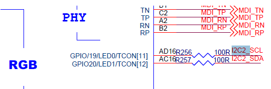
I2C 的clk,data 脚分别连接在AD16,AC16 两个pin 上面。比较特殊的是这两个pin 都是有复用功能的。所以需要disable掉其特殊功能LED/tcon。
在BD_MST160D_AH_M7221.h中可以关闭LED功能:
#define PADS_LED_MODE DISABLE
Tcon[11],Tcon[12], 未找到,属于备用的暂不处理
寄存器设置
#ifdef PADS_LED_MODE
    #if (PADS_LED_MODE != CONFIG_PADMUX_UNKNOWN)
    #define _CONFIG_LED_MODE    ((PADS_LED_MODE == ENABLE) ? BIT4 : 0)
        _RVM1(0x1eb4, _CONFIG_LED_MODE, BIT4),

    #if (PADS_LED_MODE == DISABLE)
        _MEMMAP_PM_,
        //reg_seperate_wol_led_is_gpio
        _RVM1(0x0e39, BIT7, BIT7),
        //reg_led_is_gpio
        _RVM1(0x0e39, 0, BIT0),
        _MEMMAP_nonPM_,
    #endif
    #endif
#endif
disable 掉特殊功能之后,开始配置I2C 功能
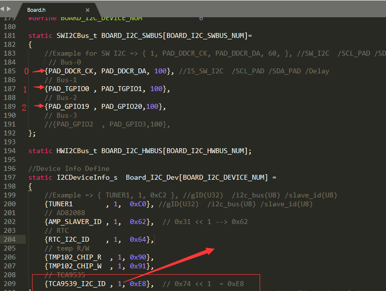
//SWI2C
#define PAD_DDCR_CK_IS_GPIO                     GPIO_IN                 //I2C-SCL (EEPROM)
#define PAD_DDCR_DA_IS_GPIO                     GPIO_IN                 //I2CM-SDA (EEPROM)

#define PAD_TGPIO0_IS_GPIO                      GPIO_IN                 //TUNER_SCL
#define PAD_TGPIO1_IS_GPIO                      GPIO_IN                 //TUNER_SDA

#define PAD_GPIO19_IS_GPIO                      GPIO_IN                 //I2C2-SCL
#define PAD_GPIO20_IS_GPIO                      GPIO_IN                 //I2C2-SDA*
将GPIO19,GPIO20 配置成了GPIO_IN,接着进行寄存器配置。如下:
    #if(PAD_GPIO19_IS_GPIO != GPIO_NONE)
        #define PAD_GPIO19_OEN (PAD_GPIO19_IS_GPIO == GPIO_IN ? BIT1: 0)
        #define PAD_GPIO19_OUT (PAD_GPIO19_IS_GPIO == GPIO_OUT_HIGH ? BIT0: 0)
        _RVM1(0x2b08, PAD_GPIO19_OUT, BIT0),
        _RVM1(0x2b08, PAD_GPIO19_OEN, BIT1),
        //reg_tconconfig11
        _RVM1(0x1ea1, 0, BIT3),   //reg[101ea1]#3 = 0b
        //reg_agc_dbg
        _RVM1(0x1e9e, 0, BIT7),   //reg[101e9e]#7 = 0b
        //reg_led_mode
        _RVM1(0x1eb4, 0, BIT4),   //reg[101eb4]#4 = 0b
        //reg_seconduartmode
        _RVM1(0x1e05, 0, BIT1 | BIT0),   //reg[101e05]#1 ~ #0 = 00b
        //reg_od2nduart
        _RVM1(0x1ea9, 0, BIT1 | BIT0),   //reg[101ea9]#1 ~ #0 = 00b
        //reg_miic_mode0
        _RVM1(0x1edc, 0, BIT0),   //reg[101edc]#0 = 0b
    #endif

    #if(PAD_GPIO20_IS_GPIO != GPIO_NONE)
        #define PAD_GPIO20_OEN (PAD_GPIO20_IS_GPIO == GPIO_IN ? BIT1: 0)
        #define PAD_GPIO20_OUT (PAD_GPIO20_IS_GPIO == GPIO_OUT_HIGH ? BIT0: 0)
        _RVM1(0x2b09, PAD_GPIO20_OUT, BIT0),
        _RVM1(0x2b09, PAD_GPIO20_OEN, BIT1),
        //reg_tconconfig12
        _RVM1(0x1ea1, 0, BIT4),   //reg[101ea1]#4 = 0b
        //reg_agc_dbg
        _RVM1(0x1e9e, 0, BIT7),   //reg[101e9e]#7 = 0b
        //reg_led_mode
        _RVM1(0x1eb4, 0, BIT4),   //reg[101eb4]#4 = 0b
        //reg_seconduartmode
        _RVM1(0x1e05, 0, BIT1 | BIT0),   //reg[101e05]#1 ~ #0 = 00b
        //reg_od2nduart
        _RVM1(0x1ea9, 0, BIT1 | BIT0),   //reg[101ea9]#1 ~ #0 = 00b
        //reg_vx1gpi_mode
        _RVM1(0x1e4a, 0, BIT1 | BIT0),   //reg[101e4a]#1 ~ #0 = 00b
        //reg_miic_mode0
        _RVM1(0x1edc, 0, BIT0),   //reg[101edc]#0 = 0b
        //reg_extint5
        _RVM1(0x1ea5, 0, BIT5),   //reg[101ea5]#5 = 0b
    #endif
其实配置成GPIO_IN 容易和 标准GPIO IN 模式产生误解。应该区别一下定义成IIC_MODE等其他宏,然后drvpadconf.c 文件中,设置寄存器即可。
寄存器值的设置才是pin 的功能设置的本质,这样就完成mboot里面pin的功能定义。
3、使用实例 - 移植TCA9539
tca959 作为一款纯IIC控制的mcu,上电后即可通过主控IC的 I2C 来控制mcu 的管脚,设置这些pin的input / output 模式,以及获取output的高低,另外也可以获取input的状态。通常主控IC的IO口不够用时用来扩展IO口。
(1)TCA9539 I2C地址确定
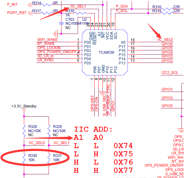
查看TCA9539 的datasheet 文档,地址部分,总共有7位,其中Slave address 的bit 位固定,另外最后两个bits 位根据原理图中地址pin 的高低来判断
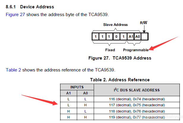
查看原理图发现,tca9539 的I2C地址脚IIC_SEL0,IIC_SEL1 接的是下拉电阻,两个PIN都是低电平,故地址应该取0x74.
结合原理图和datasheet 得到一个7bit 的I2C地址后,需要左移(x2), 末尾补零生成一个8bit 的地址(包含读写位)给软件使用,计算后该地址为 0xE8.
(2)TCA9539 I2C地址配置
找到对应板型的board.h 文件,配置tca9539 IIC 信息。包含在那一组IIC及设备的IIC 地址。其中TCA9539_I2C_ID 只是一个枚举值方便应用调用。
(3)管脚功能配置
功能配置主要是配置对应pin的输入,输出模式及输出模式的高低状态
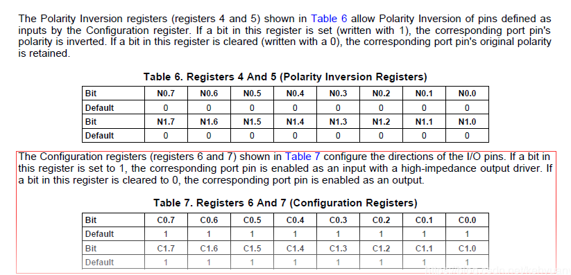
根据datasheet 的说明,寄存器0x06 , 0x07 分别配置port 0~ 7 ,port 10~17对应bit位为1 则为输入 为0 则为输出。 而寄存器0x04, 0x05 分别是设置port 0 ~ 7,port 10 ~ 17 的极性。
例如:设置P3,P4,P5,P7,P10,P11 需要设置为output,其它为input模式:
#define  TCA9539_MASK_P0  (1 << 0)
#define  TCA9539_MASK_P1  (1 << 1)
#define  TCA9539_MASK_P2  (1 << 2)
#define  TCA9539_MASK_P3  (1 << 3)
#define  TCA9539_MASK_P4  (1 << 4)
#define  TCA9539_MASK_P5  (1 << 5)
#define  TCA9539_MASK_P6  (1 << 6)
#define  TCA9539_MASK_P7  (1 << 7)

// P3,P4,P5,P7 set to output  0x47
static MAPI_U8 uTca9539_Ports_L_Mode = 0xFF  &
                        (~(TCA9539_MASK_P3)) &
                        (~(TCA9539_MASK_P4)) &
                        (~(TCA9539_MASK_P5)) &
                        (~(TCA9539_MASK_P7));

// P10,P11 set to output  0xFC
static MAPI_U8 uTca9539_Ports_H_Mode = (0xFF  & (~(TCA9539_MASK_P0)) & (~(TCA9539_MASK_P1)));
定义寄存器0x06 需要初始化的值0x47 (0100 0111), 二进制从右到左 bit0~bit7 对应port0 ~ port7;寄存器 0x07,需要初始化的值0xFC (1111 1100) ,二进制从右到左bit0 ~ bit7 对应port10 ~ port17.
    MAPI_U8  uCfgLowPorts    = 0x06;
    MAPI_U8  uCfgHighPorts   = 0x07;
    iptr = mapi_i2c::GetI2C_Dev(TCA9539_I2C_ID);
    if(iptr == NULL)
    {
        printf("[%s][%d] Invalid I2c mcu addr .
",__FUNCTION__,__LINE__);
        return MAPI_FALSE;
    }

    // config the port mode <input or output>
    if(MAPI_FALSE == iptr->WriteBytes(1,&uCfgLowPorts,1,&uTca9539_Ports_L_Mode))
    {
        printf("[%s][%d] wirte the port 0~7 failed.
",__FUNCTION__,__LINE__);
        return MAPI_FALSE;
    }
    if(MAPI_FALSE == iptr->WriteBytes(1,&uCfgHighPorts,1,&uTca9539_Ports_H_Mode))
    {
        printf("[%s][%d] wirte the port 10~17 failed.
",__FUNCTION__,__LINE__);
        return MAPI_FALSE;
    }
这样就完成input , output 模式的配置。
(4)读取输出管脚状态
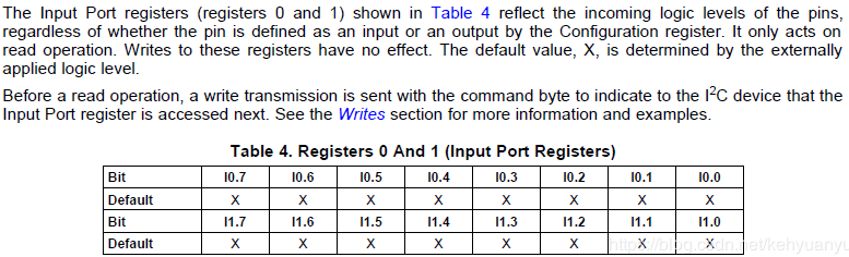
通过datasheet得到,寄存器0x00,0x01 是用来获取port 的状态:
    MAPI_U8  uLowRegAddr  = 0x00;
    MAPI_U8  uHighRegAddr = 0x01;

    MAPI_U8  uOldData     = 0x00;
    MAPI_U8  uData        = 0x00;
    MAPI_U8  uMask        = 0x00;

    MAPI_U8  uRRegAddr     = (port > TCA9539_P7) ? uHighRegAddr : uLowRegAddr;

    iptr = mapi_i2c::GetI2C_Dev(TCA9539_I2C_ID);
    if(iptr == NULL)
    {
        printf("[%s][%d] Invalid I2c mcu addr .
",__FUNCTION__,__LINE__);
        return MAPI_FALSE;
    }

    // 获取port 口该组的所有状态
    if(MAPI_FALSE == iptr->ReadBytes(1, &uRRegAddr, 1, &uOldData))
    {
        printf("[%s][%d] get the port status failed .
",__FUNCTION__,__LINE__);
        return MAPI_FALSE;
    }
    // 计算返回对应port 口的状态
    return    (uData >> (port % 10) | 0x01);
(5)设置输出管脚状态

通过datasheet可知,输出管脚的状态,通过寄存器0x2,0x03 来设置:
MAPI_BOOL device_mcu_tca9539::Set_port_Output(MAPI_U8 port, MAPI_BOOL bOutState)
{
    mapi_i2c *iptr      = NULL;
    // for output status
    MAPI_U8  uLowRegAddr  = 0x00;
    MAPI_U8  uHighRegAddr = 0x01;

    MAPI_U8  uLowWReg     = 0x02;
    MAPI_U8  uHighWReg    = 0x03;

    MAPI_U8  uOldData     = 0x00;
    MAPI_U8  uData        = 0x00;
    MAPI_U8  uMask        = 0x00;

    MAPI_U8  uRRegAddr     = (port > TCA9539_P7) ? uHighRegAddr : uLowRegAddr;
    MAPI_U8  uWRegAddr     = (port > TCA9539_P7) ? uHighWReg : uLowWReg;

    iptr = mapi_i2c::GetI2C_Dev(TCA9539_I2C_ID);
    if(iptr == NULL)
    {
        printf("[%s][%d] Invalid I2c mcu addr .
",__FUNCTION__,__LINE__);
        return MAPI_FALSE;
    }

    // 通过寄存器0x00(port0 ~ port7)/0x01(port10 ~ port17)读取当前port口的状态
    if(MAPI_FALSE == iptr->ReadBytes(1, &uRRegAddr, 1, &uOldData))
    {
        printf("[%s][%d] get the port status failed .
",__FUNCTION__,__LINE__);
        return MAPI_FALSE;
    }

    // 计算,并设置port 的新状态,其它port 状态不变
    uMask = 1 << (port % 10);
    // set the new status
    if(bOutState){
        uData = (uMask | uOldData);  // set H
    } else {
        uData = (~uMask) & uOldData;  // set L
    }

    //  对寄存器0x02(port0 ~ port7)/0x03(port10 ~ port17)写输出的高低状态
    if(MAPI_FALSE == iptr->WriteBytes(1, &uWRegAddr, 1, &uData))
    {
        printf("[%s][%d] set the new status failed .
",__FUNCTION__,__LINE__);
        return MAPI_FALSE;
    }

    printf("[%s][%d] set the P%02d to  %d.
",__FUNCTION__,__LINE__,port,bOutState);

    return MAPI_TRUE;
}
完整驱动代码 :
device_mcu_tca9539.h:
#ifndef __DEVIDE_MCU_TCA9539_H__
#define __DEVIDE_MCU_TCA9539_H__

/*@ <Include> @*/
#include "mapi_mcu.h"
#include "MsTypes.h"
#include "MTypes.h"
/*@ </Include> @*/

#define  PORT_INPUT     (1)
#define  PORT_OUTPUT    (0)

#define  OUTPUT_H       (1)
#define  OUTPUT_L       (0)

#define  TCA9539_P0     (0)
#define  TCA9539_P1     (1)
#define  TCA9539_P2     (2)
#define  TCA9539_P3     (3)
#define  TCA9539_P4     (4)
#define  TCA9539_P5     (5)
#define  TCA9539_P6     (6)
#define  TCA9539_P7     (7)

#define  TCA9539_P10     (10)
#define  TCA9539_P11     (11)
#define  TCA9539_P12     (12)
#define  TCA9539_P13     (13)
#define  TCA9539_P14     (14)
#define  TCA9539_P15     (16)
#define  TCA9539_P16     (15)
#define  TCA9539_P17     (17)

#define  TCA9539_MASK_P0  (1 << 0)
#define  TCA9539_MASK_P1  (1 << 1)
#define  TCA9539_MASK_P2  (1 << 2)
#define  TCA9539_MASK_P3  (1 << 3)
#define  TCA9539_MASK_P4  (1 << 4)
#define  TCA9539_MASK_P5  (1 << 5)
#define  TCA9539_MASK_P6  (1 << 6)
#define  TCA9539_MASK_P7  (1 << 7)

class device_mcu_tca9539 : public mapi_mcu
{
public:
    DLL_PUBLIC device_mcu_tca9539(void);
    DLL_PUBLIC ~device_mcu_tca9539(void);
    DLL_PUBLIC MAPI_BOOL Init(void);
    DLL_PUBLIC MAPI_BOOL Finalize(void);
    DLL_PUBLIC MAPI_BOOL Reset(void);
    DLL_PUBLIC MAPI_BOOL Set_port_mode(MAPI_U8 port, MAPI_BOOL bInput);
    DLL_PUBLIC MAPI_BOOL Get_port_mode(MAPI_U8 port, MAPI_U8 *uMode);
    DLL_PUBLIC MAPI_BOOL Set_port_Output(MAPI_U8 port, MAPI_BOOL bOutState);
    DLL_PUBLIC MAPI_BOOL Get_port_State(MAPI_U8 port, MAPI_BOOL *bMode, MAPI_BOOL *bState);
    DLL_PUBLIC MAPI_BOOL Tca9539Setup(void);
};
#endif // __DEVIDE_LED_DEFAULT_H__
device_mcu_tca9539.cpp:
#include <sys/stat.h>
#include <unistd.h>
#include <cstring>

#include "MsCommon.h"
#include "MsOS.h"
#include <dirent.h>

// #include "mapi_gpio.h"
#include "mapi_i2c.h"
#include "mapi_i2c_devTable.h"
#include "mapi_gpio_devTable.h"
#include "device_mcu_tca9539.h"
#include "MSrv_Control_common.h"

// P3,P4,P5,P7 set to output  0x47
static MAPI_U8 uTca9539_Ports_L_Mode = 0xFF  &
                        (~(TCA9539_MASK_P3)) &
                        (~(TCA9539_MASK_P4)) &
                        (~(TCA9539_MASK_P5)) &
                        (~(TCA9539_MASK_P7));


// P10,P11 set to output  0xFC
static MAPI_U8 uTca9539_Ports_H_Mode = (0xFF  & (~(TCA9539_MASK_P0)) & (~(TCA9539_MASK_P1)));

device_mcu_tca9539::device_mcu_tca9539(void)
{
}

device_mcu_tca9539::~device_mcu_tca9539(void)
{
}

MAPI_BOOL device_mcu_tca9539::Init(void)
{
    return Reset();
}

MAPI_BOOL device_mcu_tca9539::Finalize(void)
{
    BOOL bRet = FALSE;
    printf("Finalize TCA9539
");

    bRet = MSrv_Control_common::SetGpioDeviceStatus(MCU_RESET,FALSE);

    return (bRet) ? MAPI_TRUE : MAPI_FALSE;
}

MAPI_BOOL device_mcu_tca9539::Reset(void)
{
    BOOL bRet1 = FALSE;
    BOOL bRet2 = FALSE;
    printf("Reset TCA9539
");

    bRet1 = MSrv_Control_common::SetGpioDeviceStatus(MCU_RESET,FALSE);
    usleep(100*1000); // 100ms
    bRet2 = MSrv_Control_common::SetGpioDeviceStatus(MCU_RESET,TRUE);

    Tca9539Setup();

    return (bRet1 && bRet2) ? MAPI_TRUE : MAPI_FALSE;
}

MAPI_BOOL device_mcu_tca9539::doHandleOps(void)
{
    MAPI_BOOL    bMode      = FALSE;
    MAPI_BOOL    bPlugState = TRUE;   // plug out: ops H  ; plug in : ops L
    MAPI_BOOL    bState     = TRUE;   // ops status. H: off; L: on
    // OPS Det
    Get_port_State(TCA9539_P6, &bMode, &bPlugState);
    // OPS power
    Get_port_State(TCA9539_P17, &bMode, &bState);
    if((!bPlugState)&&(bState)){
        // // set ops on
        // uData = 0x7F; // P3 = H ,P7 = L
        // if(MAPI_FALSE == iptr->WriteBytes(1,&uLowRegAddr,1,&uData))
        // {
        //     printf("[%s][%d] wirte the port 10~17 failed.
",__FUNCTION__,__LINE__);
        //     return MAPI_FALSE;
        // }

        // usleep(100*1000);

        // uData = 0xFF; // P3 = H ,P7 = H
        // if(MAPI_FALSE == iptr->WriteBytes(1,&uLowRegAddr,1,&uData))
        // {
        //     printf("[%s][%d] wirte the port 10~17 failed.
",__FUNCTION__,__LINE__);
        //     return MAPI_FALSE;
        // }
        Set_port_Output(TCA9539_P7,MAPI_FALSE);  //  to L

        usleep(100*1000);

        Set_port_Output(TCA9539_P7,MAPI_TRUE);   //  to  H

        printf("[%s][%d] start the ops .
",__FUNCTION__,__LINE__);

        return TRUE;
    }
    return FALSE;
}

MAPI_BOOL device_mcu_tca9539::Tca9539Setup(void)
{
    mapi_i2c *iptr        = NULL;
    MAPI_U8  uCfgLowPorts    = 0x06;
    MAPI_U8  uCfgHighPorts   = 0x07;
    // for output status
    MAPI_U8  uLowRegAddr  = 0x02;
    MAPI_U8  uHighRegAddr = 0x03;
    MAPI_U8  uData        = 0x00;

    printf("[%s][%d] Enter .
",__FUNCTION__,__LINE__);

    iptr = mapi_i2c::GetI2C_Dev(TCA9539_I2C_ID);
    if(iptr == NULL)
    {
        printf("[%s][%d] Invalid I2c mcu addr .
",__FUNCTION__,__LINE__);
        return MAPI_FALSE;
    }

    // config the port mode <input or output>
    if(MAPI_FALSE == iptr->WriteBytes(1,&uCfgLowPorts,1,&uTca9539_Ports_L_Mode))
    {
        printf("[%s][%d] wirte the port 0~7 failed.
",__FUNCTION__,__LINE__);
        return MAPI_FALSE;
    }
    if(MAPI_FALSE == iptr->WriteBytes(1,&uCfgHighPorts,1,&uTca9539_Ports_H_Mode))
    {
        printf("[%s][%d] wirte the port 10~17 failed.
",__FUNCTION__,__LINE__);
        return MAPI_FALSE;
    }

    // config: set port(output) status
    uData = 0xF7; //  P3 = L  , other bit was seted to H
    if(MAPI_FALSE == iptr->WriteBytes(1,&uLowRegAddr,1,&uData))
    {
        printf("[%s][%d] wirte the port 0~7 failed.
",__FUNCTION__,__LINE__);
        return MAPI_FALSE;
    }

    // set touch power
    uData = 0xFC; //  P10, P11 = L  , other bit was seted to H
    if(MAPI_FALSE == iptr->WriteBytes(1,&uHighRegAddr,1,&uData))
    {
        printf("[%s][%d] wirte the port 0~7 failed.
",__FUNCTION__,__LINE__);
        return MAPI_FALSE;
    }

    doHandleOps();

    #if 0
    // set ops on
    uData = 0x7F; // P3 = H ,P7 = L
    if(MAPI_FALSE == iptr->WriteBytes(1,&uLowRegAddr,1,&uData))
    {
        printf("[%s][%d] wirte the port 10~17 failed.
",__FUNCTION__,__LINE__);
        return MAPI_FALSE;
    }

    usleep(100*1000);

    uData = 0xFF; // P3 = H ,P7 = H
    if(MAPI_FALSE == iptr->WriteBytes(1,&uLowRegAddr,1,&uData))
    {
        printf("[%s][%d] wirte the port 10~17 failed.
",__FUNCTION__,__LINE__);
        return MAPI_FALSE;
    }
    #endif

    #if 0
    // config the S_USB_SEL
    // uData = 0xFE; // P10 = L   android source
    uData = 0xFF; // P10 = H   OPS source
    if(MAPI_FALSE == iptr->WriteBytes(1,&uHighRegAddr,1,&uData))
    {
        printf("[%s][%d] wirte the port 10~17 failed.
",__FUNCTION__,__LINE__);
        return MAPI_FALSE;
    }
    #endif
    printf("[%s][%d] setup success.
",__FUNCTION__,__LINE__);

    return MAPI_TRUE;
}

// bInput:  TRUE --> input , FALSE  --> output
MAPI_BOOL device_mcu_tca9539::Set_port_mode(MAPI_U8 port, MAPI_BOOL bInput)
{
    printf("[%s][%d] Enter .
",__FUNCTION__,__LINE__);
    return MAPI_TRUE;
}

// uMode:  1 --> input, 0 --> output
MAPI_BOOL device_mcu_tca9539::Get_port_mode(MAPI_U8 port, MAPI_U8 *uMode)
{
    printf("[%s][%d] Enter .
",__FUNCTION__,__LINE__);
    return MAPI_TRUE;
}

MAPI_BOOL device_mcu_tca9539::Set_port_Output(MAPI_U8 port, MAPI_BOOL bOutState)
{
    mapi_i2c *iptr      = NULL;
    // for output status
    MAPI_U8  uLowRegAddr  = 0x00;
    MAPI_U8  uHighRegAddr = 0x01;

    MAPI_U8  uLowWReg     = 0x02;
    MAPI_U8  uHighWReg    = 0x03;

    MAPI_U8  uOldData     = 0x00;
    MAPI_U8  uData        = 0x00;
    MAPI_U8  uMask        = 0x00;

    MAPI_U8  uRRegAddr     = (port > TCA9539_P7) ? uHighRegAddr : uLowRegAddr;
    MAPI_U8  uWRegAddr     = (port > TCA9539_P7) ? uHighWReg : uLowWReg;

    iptr = mapi_i2c::GetI2C_Dev(TCA9539_I2C_ID);
    if(iptr == NULL)
    {
        printf("[%s][%d] Invalid I2c mcu addr .
",__FUNCTION__,__LINE__);
        return MAPI_FALSE;
    }

    // get the old status
    if(MAPI_FALSE == iptr->ReadBytes(1, &uRRegAddr, 1, &uOldData))
    {
        printf("[%s][%d] get the port status failed .
",__FUNCTION__,__LINE__);
        return MAPI_FALSE;
    }

    uMask = 1 << (port % 10);
    // set the new status
    if(bOutState){
        uData = (uMask | uOldData);  // set H
    } else {
        uData = (~uMask) & uOldData;  // set L
    }

    if(MAPI_FALSE == iptr->WriteBytes(1, &uWRegAddr, 1, &uData))
    {
        printf("[%s][%d] set the new status failed .
",__FUNCTION__,__LINE__);
        return MAPI_FALSE;
    }

    printf("[%s][%d] set the P%02d to  %d.
",__FUNCTION__,__LINE__,port,bOutState);

    return MAPI_TRUE;
}

MAPI_BOOL device_mcu_tca9539::Get_port_State(MAPI_U8 port, MAPI_BOOL *bMode, MAPI_BOOL *bState)
{
    mapi_i2c *iptr      = NULL;
    // used for port status
    MAPI_U8  uInLowRegAddr  = 0x00;
    MAPI_U8  uInHighRegAddr = 0x01;
    MAPI_U8  uRegAddr  = (port > TCA9539_P7) ? uInHighRegAddr : uInLowRegAddr;

    // for port mode
    MAPI_U8  uLowPorts    = 0x06;
    MAPI_U8  uHighPorts   = 0x07;
    MAPI_U8  uModeRegAddr = (port > TCA9539_P7) ? uHighPorts : uLowPorts;
    MAPI_U8  uData        = 0x00;
    MAPI_U8  uMode        = 0x00;

    if(NULL == bMode || NULL == bState || (port > TCA9539_P17 || port < TCA9539_P0))
    {
        printf("[%s][%d] param error .
",__FUNCTION__,__LINE__);
        return MAPI_FALSE;
    }

    iptr = mapi_i2c::GetI2C_Dev(TCA9539_I2C_ID);
    if(iptr == NULL)
    {
        printf("[%s][%d] Invalid I2c mcu addr .
",__FUNCTION__,__LINE__);
        return MAPI_FALSE;
    }

    // get the port mode <input/outputO>
    if(MAPI_FALSE == iptr->ReadBytes(1, &uModeRegAddr, 1, &uData))
    {
        printf("[%s][%d] get the old status failed .
",__FUNCTION__,__LINE__);
        return MAPI_FALSE;
    }

    uMode = (uData >> (port % 10)) & 0x01;
    *bMode = uMode;

    uData = 0x00;
    if(MAPI_FALSE == iptr->ReadBytes(1, &uRegAddr, 1, &uData))
    {
        printf("[%s][%d] get the port status failed .
",__FUNCTION__,__LINE__);
        return MAPI_FALSE;
    }

    printf("[%s][%d] uRegAddr [0x%02x] , uData [0x%02x]
", __FUNCTION__,__LINE__, uRegAddr, uData);

    *bState = (uData >> (port % 10) & 0x01);

    printf("[%s][%d] P%02d mode <%s> , state [%d]
", __FUNCTION__,__LINE__, port, (bMode ? "Input":"Output"), *bState);
    return MAPI_TRUE;
}