目标:搭建S9S12G单片机最小系统,配置常用片上资源
备注:软硬件设计参考官方开发板-DEVKIT-S12G128开发板

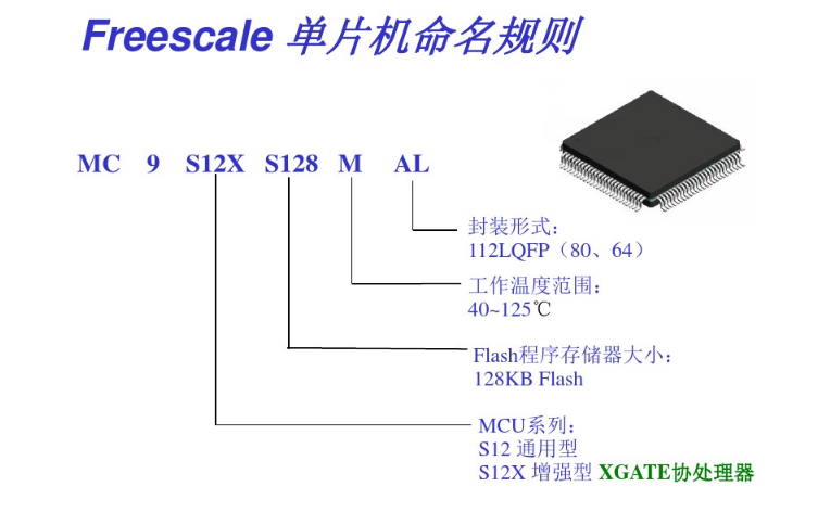
0. S9S12G系列单片机概况
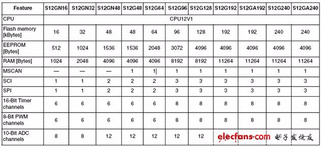

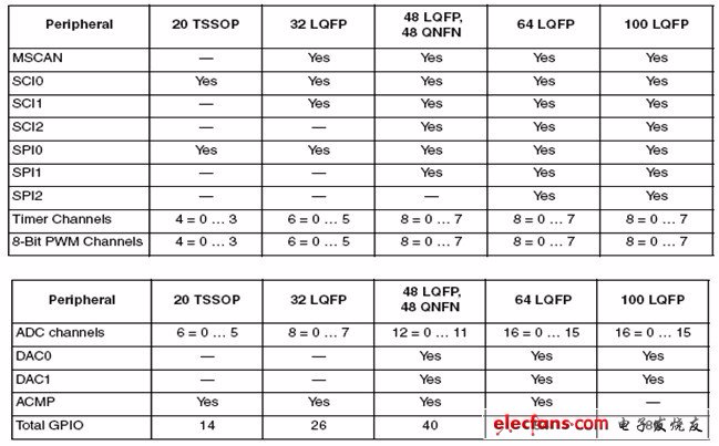
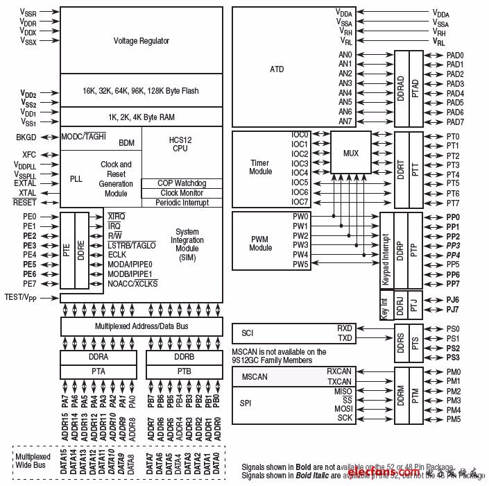
在这个系列里面可应用的模块包括以下特点:
S12内核
高达240KB的片内在线可编程FLASH存储器防纠错闪存
高达4KB防纠错EEPROM
高达11KB片内SRAM
拥有内部滤波器的锁相环回路(IPLL)频率乘法器
4-16MHz振幅控制穿透振荡器
1MHz内部RC振荡器
定时单元(TIM)支持达到8通道(提供16位输入俘获,输出比较,计数,脉冲存储器功能)
多达8*8通道脉宽调节(PWM)模块
多达16通道,10位或12位分辨率逐次近似计算法模数转换器(ADC)
多达两个8位数模转换器(DAC)
多达一个5V模拟比较器(ACMP)
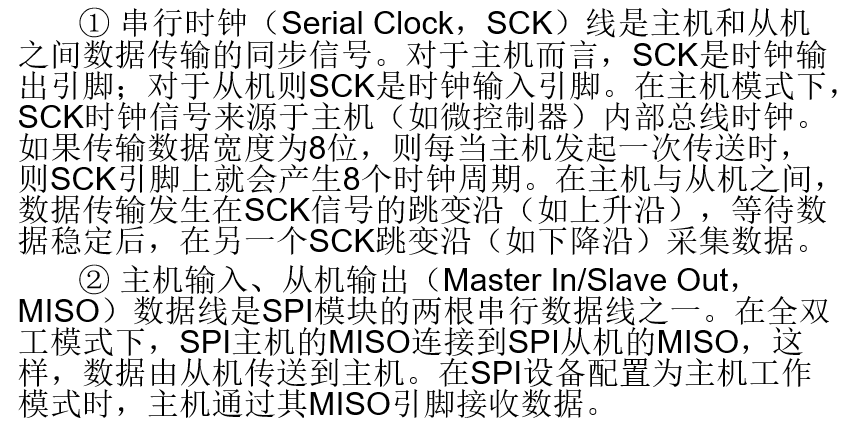
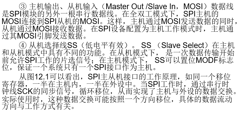
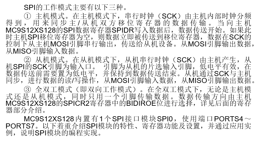
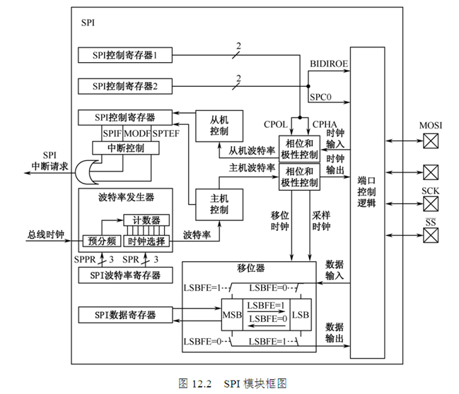
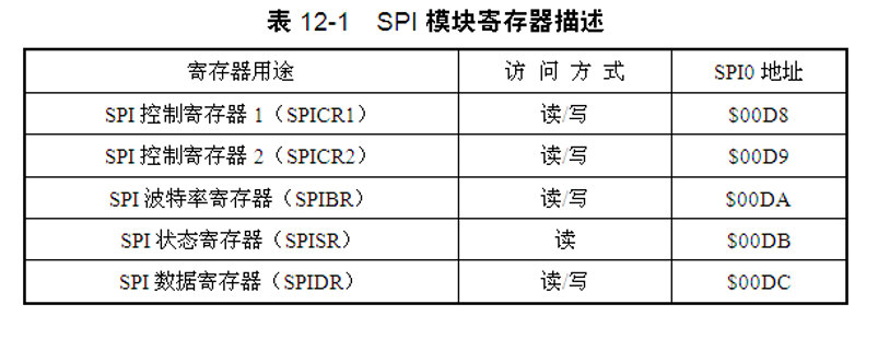
多达3个串行外围接口模块(SPI)
多达3个串行通信接口(SCI)模块(支持LIN通信)
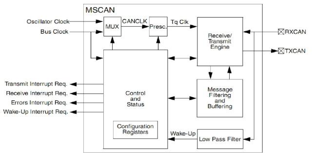
多达一个多级控制局域网(MSCAN)模块(支持CAN2.0 A/B 协议)
在线片内稳压器(VREG)用于控制内部供给和内部电压
自动周期性中断(API)
固定电压基准精度参考ADC转换器
1. 搭建最小系统
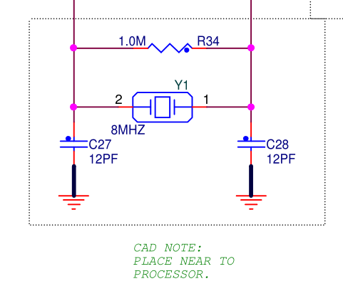
1.1 晶振电路
1.2 复位电路
1.3 BDM调试电路
1.4 供电电路
2. 配置片上资源
时钟、定时器、GPIO、外部中断、PWM、EE、IIC、SCI、SPI、CAN、看门狗
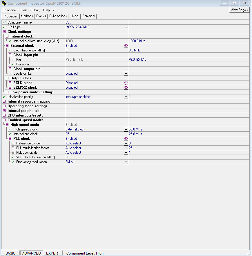
2.1 时钟配置
/*******************************************************************************
Function Name : PLL_Init
Parameters    : unsigned char pll_synr
                unsigned char pll_refdv
                unsigned char pll_postdivNONE
Modifies      : NONE
Returns       : NONE
Notes         : Sets BUSCLK = 40MHz from OSCCLK = 4MHz
Issues        : NONE
*******************************************************************************/
static void PLL_Init(unsigned char pll_synr, unsigned char pll_refdv, unsigned char pll_postdiv)
{
  CPMUPROT = 0x26U;                    /* Disable protection of clock configuration registers */
  CLKSEL = 0X00;   //disengage PLL to system
  PLLCTL_PLLON = 1;  //turn on PLL
  //CPMUREFDIV_REFFRQ = 2;

  /* CPMUSYNR: VCOFRQ1=0,VCOFRQ0=0,SYNDIV5=0,SYNDIV4=0,SYNDIV3=0,SYNDIV2=1,SYNDIV1=0,SYNDIV0=1 */
  CPMUSYNR = pll_synr;        // Set the multiplier register [3]
  /* CPMUREFDIV: REFFRQ1=0,REFFRQ0=1,REFDIV3=0,REFDIV2=0,REFDIV1=0,REFDIV0=1 */
  CPMUREFDIV = pll_refdv;     // Set the divider register [1]
  /* CPMUPOSTDIV: POSTDIV4=0,POSTDIV3=0,POSTDIV2=0,POSTDIV1=0,POSTDIV0=0 */
  CPMUPOSTDIV = pll_postdiv;  // Set the post divider register [1]

  CPMUOSC_OSCE = 1;			  // External oscillator enable. 8MHZ.        FREF=FOSC/(REFDIV+1)
  _asm(nop);
  _asm(nop);
  while(!CPMUFLG_LOCK);       // Wait till the PLL VCO is within tolerance

  CPMUCLKS_PLLSEL = 1;        // Select clock source from PLLCLK,bus=fPLL/2; COP is clocked from OSCCLK

  ECLKCTL_NECLK=0;            // Enable the BusClk output at ECLK pin to see busclk if necessary
  CPMUPROT = 0x00U;                    /* Enable protection of clock configuration registers */
}

PLL_Init(0x58, 0x07, 0x00); // 25MHz BUSCLK from 8 MHZ oscclk, PEE mode,系统时钟fbus = fPLL / 2
  //--- PLL Initialization ---------------
  //SetPEEmodeBUSCLK(0x58, 0x03, 0x00);   // 25MHz BUSCLK from 4 MHZ oscclk, PEE mode
  //SetPEEmodeBUSCLK(0x58, 0x07, 0x00);   // 25MHz BUSCLK from 8 MHZ oscclk, PEE mode
  //SetPEEmodeBUSCLK(0x03, 0x40, 0x00);   // 16MHz BUSCLK from 4 MHZ oscclk, PEE mode
  //SetPEEmodeBUSCLK(0x01, 0x80, 0x00);   // 16MHz BUSCLK from 8 MHZ oscclk, PEE mode
  //SetPEEmodeBUSCLK(0x01, 0x80, 0x07);   // 2MHz BUSCLK from 8 MHZ oscclk, PEE mode
  //SetPEEmodeBUSCLK(0x02, 0x80, 0x00);   // 24MHz BUSCLK from 8 MHZ oscclk, PEE mode
2.2 定时器配置
2.3 GPIO配置
/*****************************************************************
**    程序名:MC9S12G128 IO
**    参  数:无
**    功  能:G128 IO口LED按一定间隔时间闪烁
**    注  意:LED位于G128 PD0口
**    作  者:赵露露
**    版  本:v1.0
**    时  间:2012.5.6
******************************************************************/
#include <hidef.h>            /* common defines and macros */
#include "derivative.h"       /* derivative-specific definitions */


/*****************************************************************
**    函数名: delayms()
**    参  数:xms
**    功  能:在16MHz总线时钟下大约延时xms毫秒
**    注  意:
******************************************************************/
void delayms(uint xms)
{
  uint z,j;
	for(z=xms;z>0;z--)
	    for(j=1600;j>0;j--);
}

void main(void)
{

  DDRD = 0xFF;                //设置PD(0-7)方向为输出
  PORTD = 0xFF;               //设置PD(0-7)输出高电平
 while(1)
  {
    PORTD_PD0 = ~PORTD_PD0; //对PD0口取反
    delayms(1000);          //延时
  }


}
2.4 外部中断配置
/*****************************************************************
**    程序名:MC9S12G128 按键检测(中断方式)
**    参  数:无
**    功  能:当按下按键后�LED关闭0.1秒
**    注  意:LED位于G128 PD0口,按键位于G128 PP0口
**    作  者:赵露露
**    版  本:v1.0
**    时  间:2012.5.7
******************************************************************/
#include <hidef.h>            /* common defines and macros */
#include "derivative.h"       /* derivative-specific definitions */


/*****************************************************************
**    函数名: delayms()
**    参  数:xms
**    功  能:在16MHz总线时钟下大约延时xms毫秒
**    注  意:
******************************************************************/
void delayms(uint xms)
{
  uint z,j;
	for(z=xms;z>0;z--)
	    for(j=1600;j>0;j--);
}
//中断函数
//将中断函数置于非分页区内,地址空间超过了16位的寻址空间64K,但是它的中断向量地址只有16位,所以中断程序要执行,就得在它16位的寻址空间也即非分页区内,这就是为什么会将S12的中断函数置于非分页区的原因。
#pragma CODE_SEG __NEAR_SEG NON_BANKED

interrupt 56 void IRQ_ISR(void)       //56为PP口中断向量号,它是由文件"mc9s12g128.h"中定义的宏,可在这个文件中搜索"VectorNumber"查找各个中断的中断向量号
{
  DisableInterrupts;                  //关闭中断
  PIFP_PIFP0 = 1;                     //清除PP0的中断标志位
  PORTD_PD0 = 1;                      //关闭LED
  delayms(100);                       //延时以至于可以观察到效果
  EnableInterrupts;                   //打开中断
}
#pragma CODE_SEG DEFAULT              //将后续代码置于默认区域内

void main(void)
{

  DDRD = 0xFF;                //设置PD(0-7)方向为输出
  PORTD = 0xFF;               //设置PD(0-7)输出高电平

  DDRP_DDRP0 = 0;             //设置PP0口方向为输入
  PERP_PERP0 = 1;             //设置PP0口拉设备启用
  PPSP_PPSP0 = 1;             //打开PP0口上拉
  PIEP_PIEP0 = 1;             //设置PP0口中断使能

  EnableInterrupts;           //打开中断
 while(1)
  {
    PORTD_PD0 = 0;            //打开LED
  }

}
/*****************************************************************
** 程序名:MC9S12G128 按键检测
** 参 数:无
** 功 能:当按下按键后,打开或关闭LED灯
** 注 意:LED位于G128 PD0口,按键位于G128 PB0口
** 作 者:赵露露
** 版 本:v1.0
** 时 间:2012.5.6
******************************************************************/
#include <hidef.h> /* common defines and macros */
#include "derivative.h" /* derivative-specific definitions */
/*****************************************************************
** 函数名: delayms()
** 参 数:xms
** 功 能:在16MHz总线时钟下大约延时xms毫秒
** 注 意:
******************************************************************/
void delayms(uint xms)
{
uint z,j;
for(z=xms;z>0;z--)
for(j=1600;j>0;j--);
}
void main(void)
{
DDRD = 0xFF; //设置PD(0-7)方向为输出
DDRB = 0x00; //设置PB(0-7)方向为输入
PORTD = 0xFF; //设置PD(0-7)输出高电平
PUCR_PUPBE = 1; //PB口上拉使能
while(1)
{
//按键未按下
if(PORTB_PB0 == 1)
{
PORTD_PD0 = 1; //LED关闭
}
//按键按下
else
{
delayms(10); //延时消除按键抖动
if(PORTB_PB0 == 0)
PORTD_PD0 = 0; //LED打开
}
}
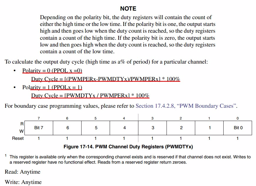
}2.5 PWM配置

/*****************************************************************
** 程序名:MC9S12G128 PWM
** 参 数:无
** 功 能:初始化G128PWM,频率,16KHz,占空比50%
** 注 意:总线时钟需超频至32MHz
** 作 者:赵露露
** 版 本:v1.0
** 时 间:2012.5.11
******************************************************************/
#include <hidef.h> /* common defines and macros */
#include "derivative.h" /* derivative-specific definitions */
/*****************************************************************
** 函数名: delayms()
** 参 数:xms
** 功 能:在32MHz总线时钟下大约延时xms毫秒
** 注 意:
******************************************************************/
void delayms(uint xms)
{
uint z,j;
for(z=xms;z>0;z--)
for(j=5340;j>0;j--);
}
/*****************************************************************
** 函数名: PLL_Init()
** 参 数:无
** 功 能:将G128超频至16M,32M,64M
** 注 意:
******************************************************************/
void PLL_Init(void)
{
CPMUPROT = 0x26; //保护时钟配置寄存器
CPMUCLKS_PSTP = 0; //禁用PLL
CPMUCLKS_PLLSEL = 1; //选择PLL作为系统时钟源
CPMUOSC_OSCE = 1; //外部晶振使能
CPMUSYNR = 0x07; //fVCO= 2*fOSC*(SYNDIV + 1)/(REFDIV + 1)
CPMUREFDIV = 0x03; //16M:07,0F;32M:07,07;64M:07,03
CPMUPOSTDIV = 0x00; // PLL CLOCK = VCO CLOCK / (POSTDIV + 1)
//BUS CLOCK = PLL CLOCK/2
_asm(nop);
_asm(nop);
CPMUPLL=0x10; //锁相环调频启用,用以减少噪音
while(CPMUFLG_LOCK == 0); //等待PLL稳定
CPMUPROT = 0x00; //关闭保护时钟
}
/*****************************************************************
** 函数名: PWM_Init()
** 参 数:无
** 功 能:初始化G128的PWM模块
** 注 意:01 23通道级联使用
******************************************************************/
static void PWM_Init(void)
{
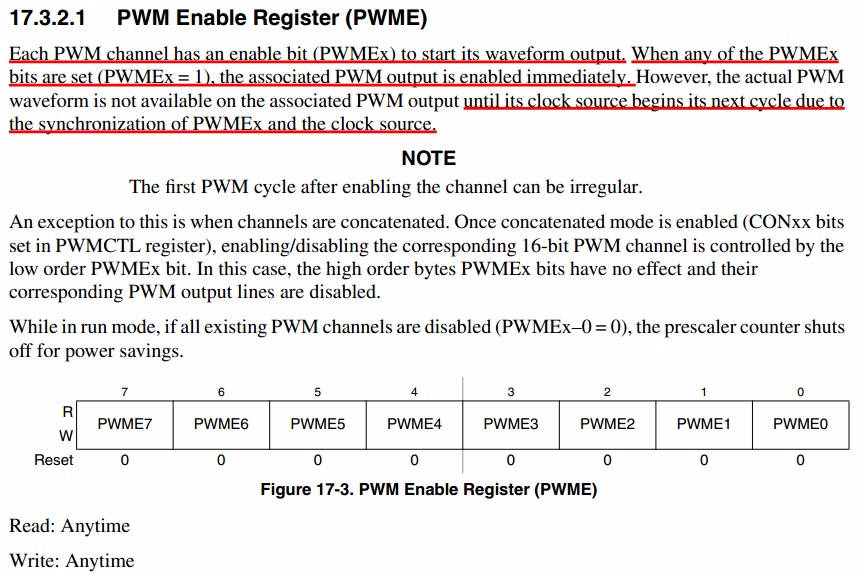
PWME_PWME0 = 0; //禁止通道
PWME_PWME1 = 0;
PWME_PWME2 = 0;
PWME_PWME3 = 0;
PWMCTL_CON01 = 1; //01,23通道连接成16位PWM使用
PWMCTL_CON23 = 1;
PWMCNT0 = 0x00; //0123通道计数被禁止
PWMCNT1 = 0x00;
PWMCNT2 = 0x00;
PWMCNT3 = 0x00;
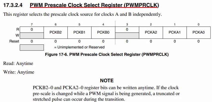
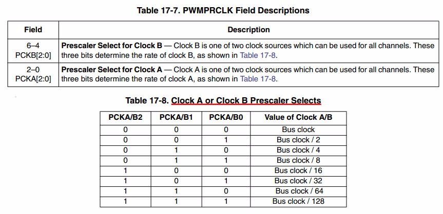
PWMPRCLK = 0x00; //预分频 A、B 1分频 32MHz
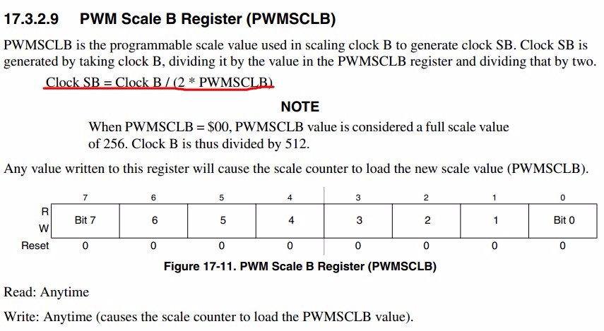
PWMSCLB = 0x01; //0x01 : SB_CLK = B_CLK / (1*2) == 16MHz
//SB时钟设置
PWMSCLA = 0x01; //0x01 : SA_CLK = B_CLK / (1*2) == 16MHz
//SA时钟设置
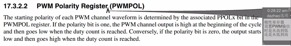
PWMPOL_PPOL1 = 1; //起始高电平
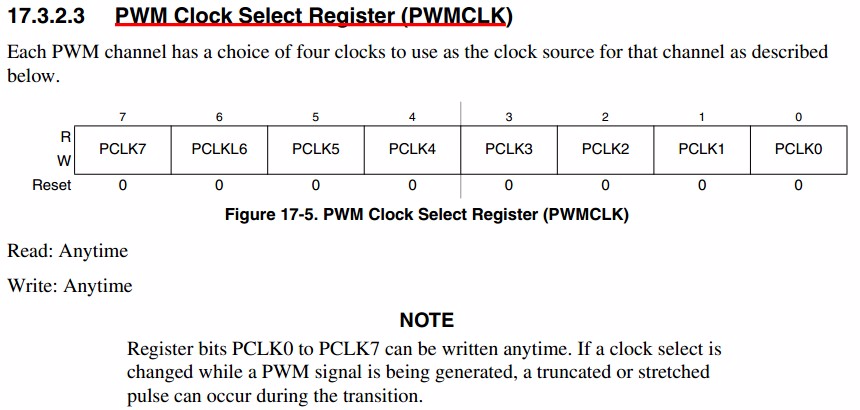
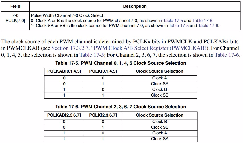
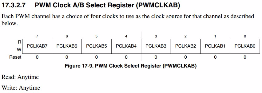
PWMCLK_PCLK1 = 1; //PWM1---SB 时钟源的选择
PWMPOL_PPOL3 = 1;
PWMCLK_PCLK3 = 1; //SA时钟设置
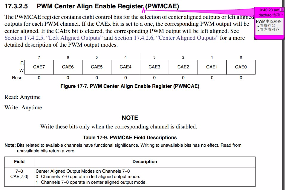
PWMCAE_CAE1 = 0; //对齐方式设置
PWMCAE_CAE3 = 0;
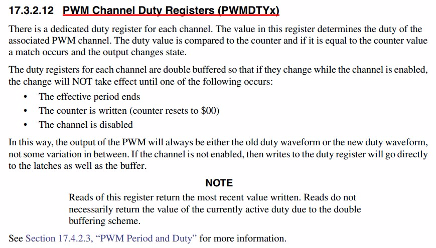
PWMDTY01 = 500; // Duty cycle = 占空比寄存器设置 3500
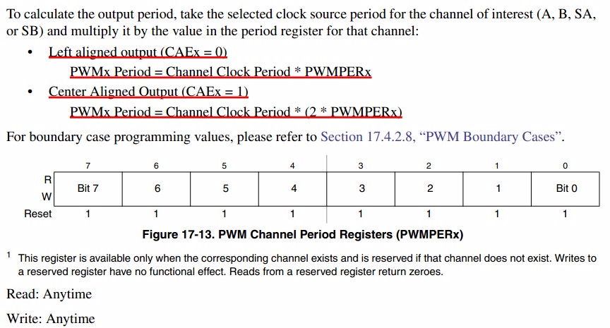
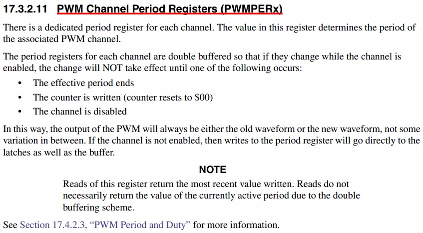
PWMPER01 = 1000; //周期==(1/16M)*(1000)= ms; 16kHz 周期寄存器设置
PWMDTY23 = 500;
PWMPER23 = 1000; //周期==(1/16M)*(1000)= ms; 16kHz
PWME_PWME1 = 1; //Enable PWM 使能
PWME_PWME3 = 1;
}
void main(void)
{
DDRD = 0xFF; //设置PD(0-7)方向为输出
PORTD = 0xFF; //设置PD(0-7)输出高电平
PLL_Init();
PWM_Init();
while(1)
{
PORTD_PD0 = ~PORTD_PD0; //LED取反
delayms(1000);
}
}

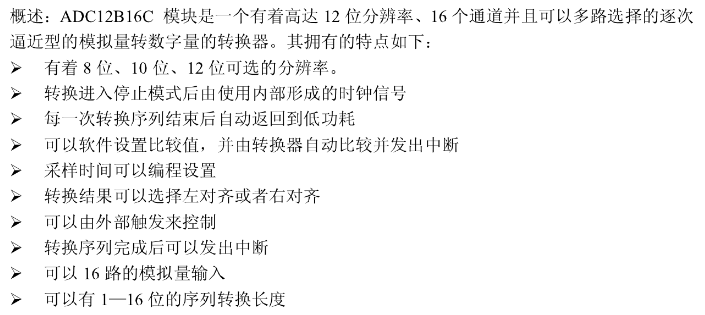
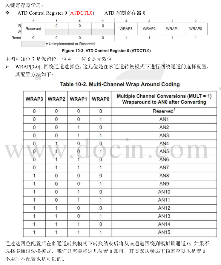
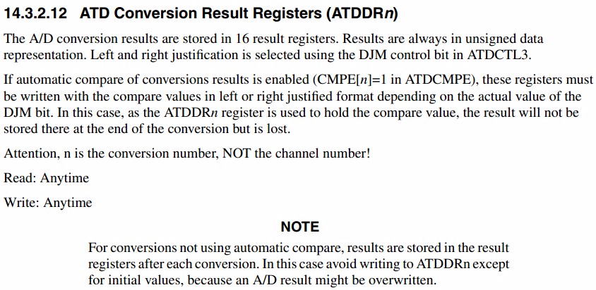
2.6 ADC配置


/*****************************************************************
** 函数名: AD_Init()
** 参 数:无
** 功 能:AD初始化
** 注 意:
******************************************************************/
void AD_Init(void)
{
//8路通道
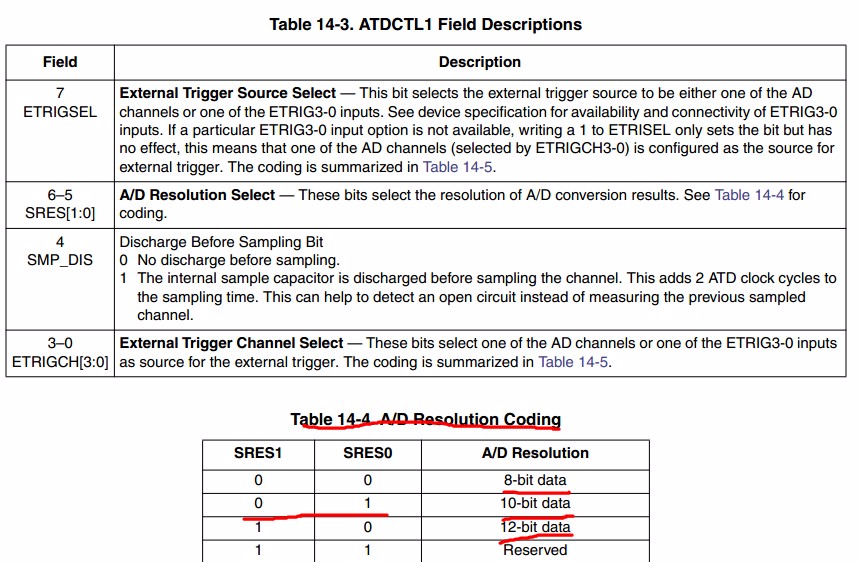
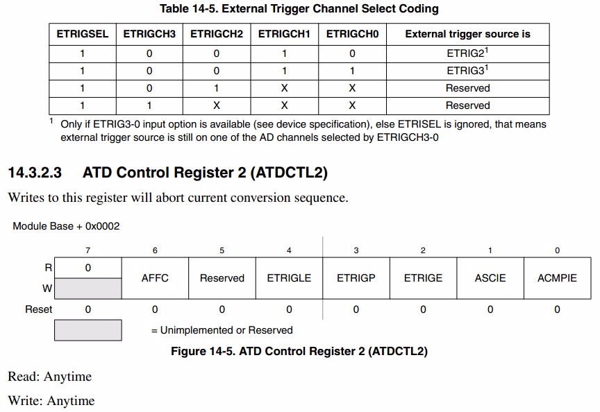
ATDCTL1=0x20; //7:1-外部触发,65:00-8位精度,01-10位精度,4:放电,3210:ch
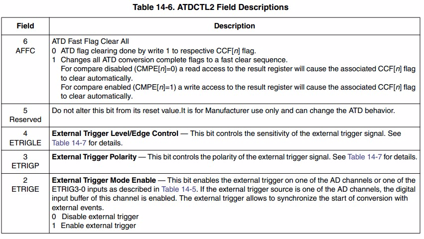
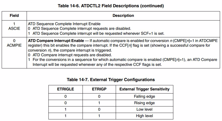
ATDCTL2=0x40; //忽略外部触发,中断禁止
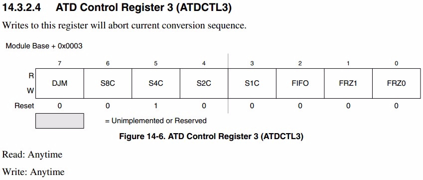
ATDCTL3=0x80; //右对齐无符号,每次转换8个序列, 无缓冲, 冻结模式下继续转换
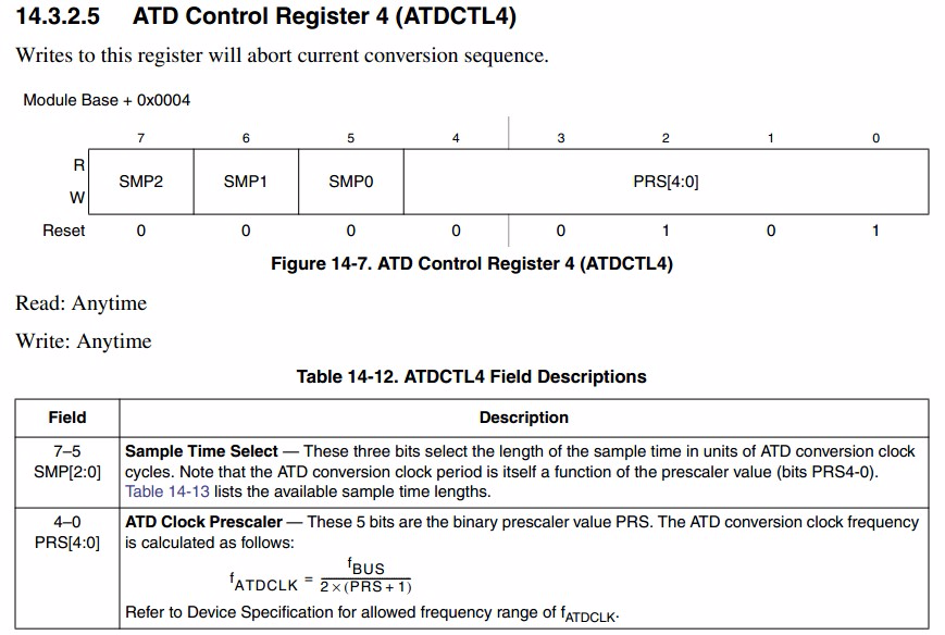
ATDCTL4=0x01; //765:采样时间为4个AD时钟周期,ATDClock=[BusClock*0.5]/[PRS+1]
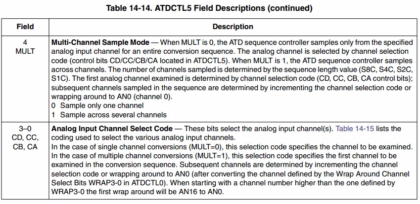
ATDCTL5=0x30; //6:0特殊通道禁止,5:1连续转换 ,4:1多通道轮流采样
ATDDIEN=0x00; //作为AD用,IO口禁止
}
/*****************************************************************
** 函数名: ReadATD()
** 参 数:ch:读取第ch通道电压值
** 功 能:读取AD采集的电压值
** 注 意:10位精度
******************************************************************/
ReadATD(byte ch)
{
signed int ad = 0; //存放采集电压值
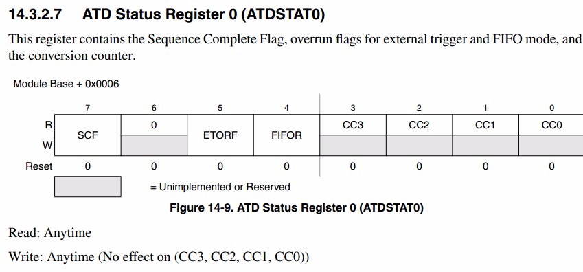
while(ATDSTAT0_SCF == 0); //等待转换完成
switch(ch)
{
default:
case 0:
ad = ATDDR0;
break;
case 1:
ad = ATDDR1;
break;
case 2:
ad = ATDDR2;
break;
case 3:
ad = ATDDR3;
break;
case 4:
ad = ATDDR4;
break;
case 5:
ad = ATDDR5;
break;
case 6:
ad = ATDDR6;
break;
case 7:
ad = ATDDR7;
break;
}
return ad;
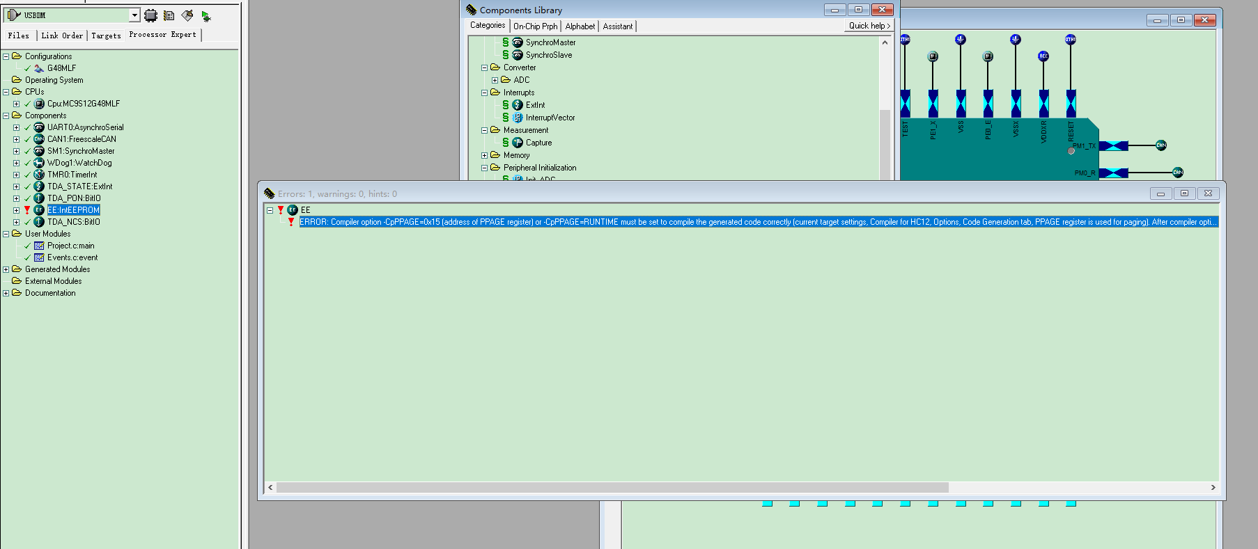
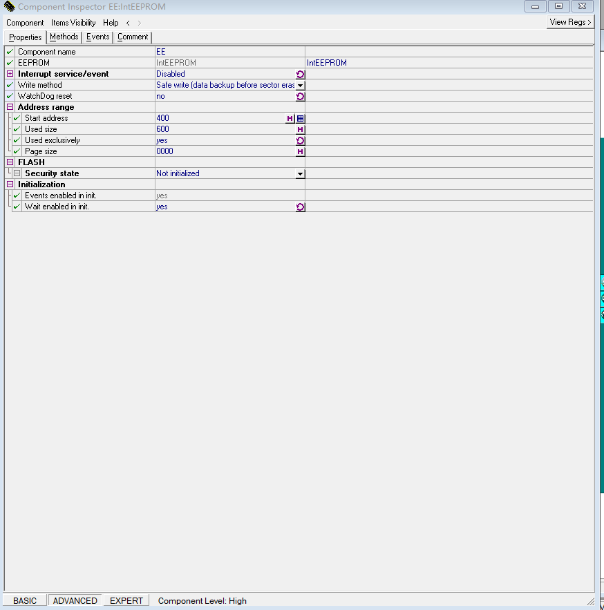
}2.7 EE配置
2.8 IIC配置
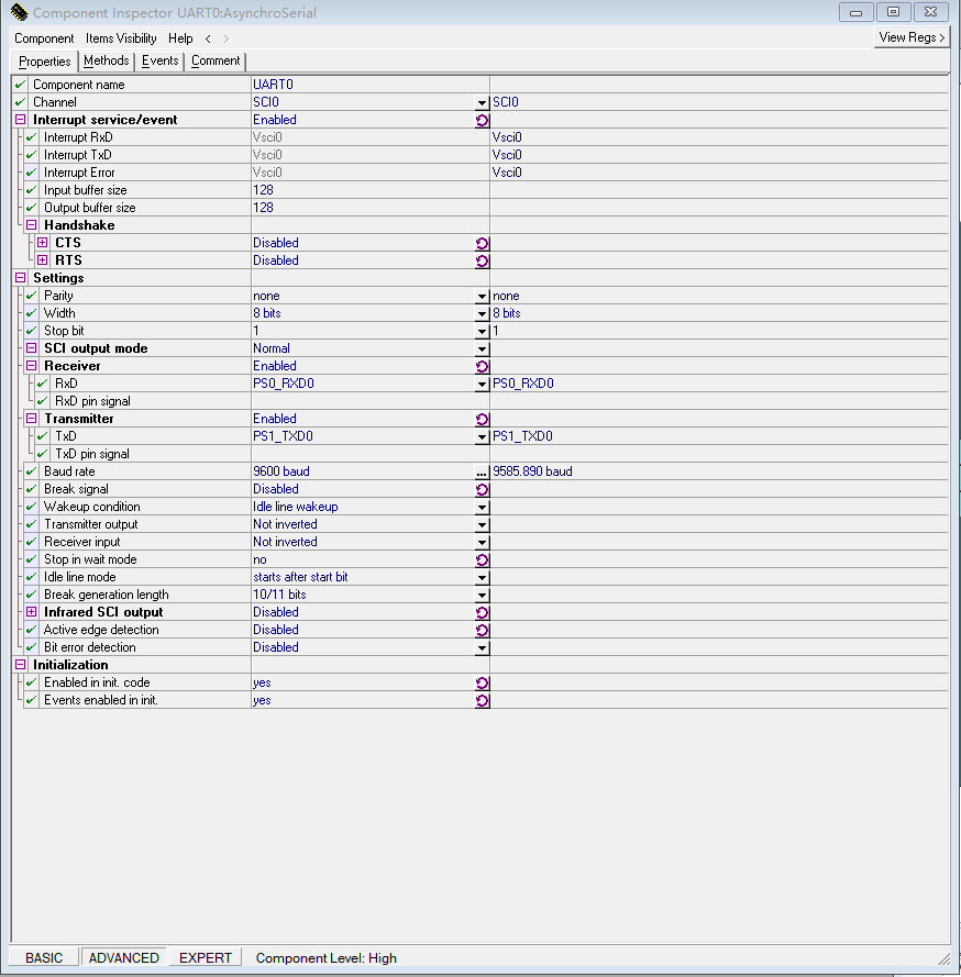
2.9 SCI配置
/*****************************************************************
** 程序名:MC9S12G128 串口
** 参 数:BusCLK_nM 总线时钟
** 功 能:使用G128串口通信
** 注 意:程序中使用的是G128的第一路串口,即(S0,S1)
** 作 者:
** 版 本:v1.0
** 时 间:2012.5.9
******************************************************************/
#include <hidef.h>
#include "derivative.h"
#include <ctype.h>
#include <string.h>
#include <stdarg.h>
#define BusCLK_nM 16000000
#pragma CODE_SEG DEFAULT
#define CR_as_CRLF TRUE // if true , you can use "
" to act as CR/LF,
// if false, you have to use "
",but can get a higher speed
static int do_padding;
static int left_flag;
static int len;
static int num1;
static int num2;
static char pad_character;
unsigned char uart_getkey(void)
{
while(!(SCI0SR1&0x80)) ; //keep waiting when not empty
return SCI0DRL;
}
void uart_putchar(unsigned char ch)
{
if (ch == '
')
{
while(!(SCI0SR1&0x80)) ;
SCI0DRL= 0x0d; //output'CR'
return;
}
while(!(SCI0SR1&0x80)) ; //keep waiting when not empty
SCI0DRL=ch;
}
void putstr(char ch[])
{
unsigned char ptr=0;
while(ch[ptr]){
uart_putchar((unsigned char)ch[ptr++]);
}
}
static void padding( const int l_flag)
{
int i;
if (do_padding && l_flag && (len < num1))
for (i=len; i<num1; i++)
uart_putchar( pad_character);
}
static void outs( char* lp)
{
/* pad on left if needed */
len = strlen( lp);
padding( !left_flag);
/* Move string to the buffer */
while (*lp && num2--) uart_putchar( *lp++);
/* Pad on right if needed */
len = strlen( lp);
padding( left_flag);
}
static void reoutnum(unsigned long num, unsigned int negative, const long base )
{
char* cp;
char outbuf[32];
const char digits[] = "0123456789ABCDEF";
/* Build number (backwards) in outbuf */
cp = outbuf;
do {
*cp++ = digits[(int)(num % base)];
} while ((num /= base) > 0);
if (negative) *cp++ = '-';
*cp-- = 0;
/* Move the converted number to the buffer and */
/* add in the padding where needed. */
len = strlen(outbuf);
padding( !left_flag);
while (cp >= outbuf)
uart_putchar( *cp--);
padding( left_flag);
}
static void outnum(long num, const long base ,unsigned char sign)//1, signed 0 unsigned
{
unsigned int negative;
if ( (num < 0L) && sign )
{
negative=1;
num = -num;
}
else negative=0;
reoutnum(num,negative,base);
}
static int getnum( char** linep)
{
int n;
char* cp;
n = 0;
cp = *linep;
while (isdigit(*cp))
n = n*10 + ((*cp++) - '0');
*linep = cp;
return(n);
}
void printp( char* ctrl, ...)
{
int long_flag;
int dot_flag;
char ch;
va_list argp;
va_start( argp, ctrl);
for ( ; *ctrl; ctrl++) {
/* move format string chars to buffer until a format control is found. */
if (*ctrl != '%') {
uart_putchar(*ctrl);
#if CR_as_CRLF==TRUE
if(*ctrl=='
') uart_putchar('
');
#endif
continue;
}
/* initialize all the flags for this format. */
dot_flag = long_flag = left_flag = do_padding = 0;
pad_character = ' ';
num2=32767;
try_next:
ch = *(++ctrl);
if (isdigit(ch)){
if (dot_flag)
num2 = getnum(&ctrl);
else {
if (ch == '0')
pad_character = '0';
num1 = getnum(&ctrl);
do_padding = 1;
}
ctrl--;
goto try_next;
}
switch (tolower(ch)) {
case '%':
uart_putchar( '%');
continue;
case '-':
left_flag = 1;
break;
case '.':
dot_flag = 1;
break;
case 'l':
long_flag = 1;
break;
case 'd':
if (long_flag ==1 )
{
if(ch == 'D') {outnum( va_arg(argp, unsigned long), 10L , 0);continue;}
else /* ch == 'd' */ {outnum( va_arg(argp, long), 10L,1);continue;}
}
else
{
if(ch == 'D') {outnum( va_arg(argp, unsigned int),10L,0);continue;}
else /* ch == 'd' */
{
outnum( va_arg(argp, int), 10L,1);
continue;
}
}
case 'x': // X 无符号 , x 有符号
if (long_flag ==1 )
{
if(ch == 'X')
{
outnum( va_arg(argp, unsigned long), 16L,0);
continue;
}
else /* ch == 'x' */
{
outnum( va_arg(argp, long), 16L,1);
continue;
}
}
else
{
if(ch == 'X')
{
outnum( va_arg(argp, unsigned int), 16L,0);
continue;
}
else /* ch == 'x' */
{
outnum( va_arg(argp, int), 16L,1);
continue;
}
} //如果按照16进制打印,将全部按照无符号数进行
continue;
case 's':
outs( va_arg( argp, char*));
continue;
case 'c':
uart_putchar( va_arg( argp, int));
continue;
default:
continue;
}
goto try_next;
}
va_end( argp);
}
/*****************************************************************
** 函数名: PLL_Init()
** 参 数:无
** 功 能:将总线时钟倍频至16M,32M,64M
** 注 意:
******************************************************************/
void PLL_Init(void)
{
CPMUPROT = 0x26; //保护时钟配置寄存器
CPMUCLKS_PSTP = 0; //禁用PLL
CPMUCLKS_PLLSEL = 1; //选择PLL作为系统时钟源
CPMUOSC_OSCE = 1; //外部晶振使能
CPMUSYNR = 0x07; //fVCO= 2*fOSC*(SYNDIV + 1)/(REFDIV + 1)
CPMUREFDIV = 0x07; //16M:07,0F;32M:07,07;64M:07,03
CPMUPOSTDIV = 0x00; // PLL CLOCK = VCO CLOCK / (POSTDIV + 1)
_asm(nop);
_asm(nop);
CPMUPLL=0x10; //锁相环调频启用,用以减少噪音
while(CPMUFLG_LOCK == 0); //等待PLL稳定
CPMUPROT = 0x00; //关闭保护时钟
CPMUCLKS_PLLSEL = 1; //使能PLL
}
static void SCI_Init(void)
{
SCI0CR1 = 0x00;
SCI0CR2 = 0x2c; //使能接收中断,发送与接收使能
SCI0BD = BusCLK_nM/16/9600;//超频至32MHz时,总线频率为16MHz
//SCI0BDL=busclk/(16*SCI0BDL)
//busclk 8MHz, 9600bps,SCI0BD=0x34
//busclk 16MHz, 9600bps,SCI0BD=0x68
//busclk 24MHz, 9600bps,SCI0BD=0x9C
} //busclk 32MHz, 9600bps,SCI0BD=0xD0
//busclk 40MHz, 9600bps,SCI0BD=0x106
/*****************************************************************
** 函数名: delayms()
** 参 数:xms
** 功 能:在32MHz总线时钟下大约延时xms毫秒
** 注 意:
******************************************************************/
void delayms(uint xms)
{
uint z,j;
for(z=xms;z>0;z--)
for(j=5340;j>0;j--);
}
void main(void)
{
unsigned char LedCnt=0;
PLL_Init();
SCI_Init();
DDRD = 0xFF;
PORTD = 0;
EnableInterrupts;
for(;;)
{
delayms(1000); //延时
PORTD = ~LedCnt; //LED取反
putstr("http://blog.csdn.net/dazhaozi
");
}
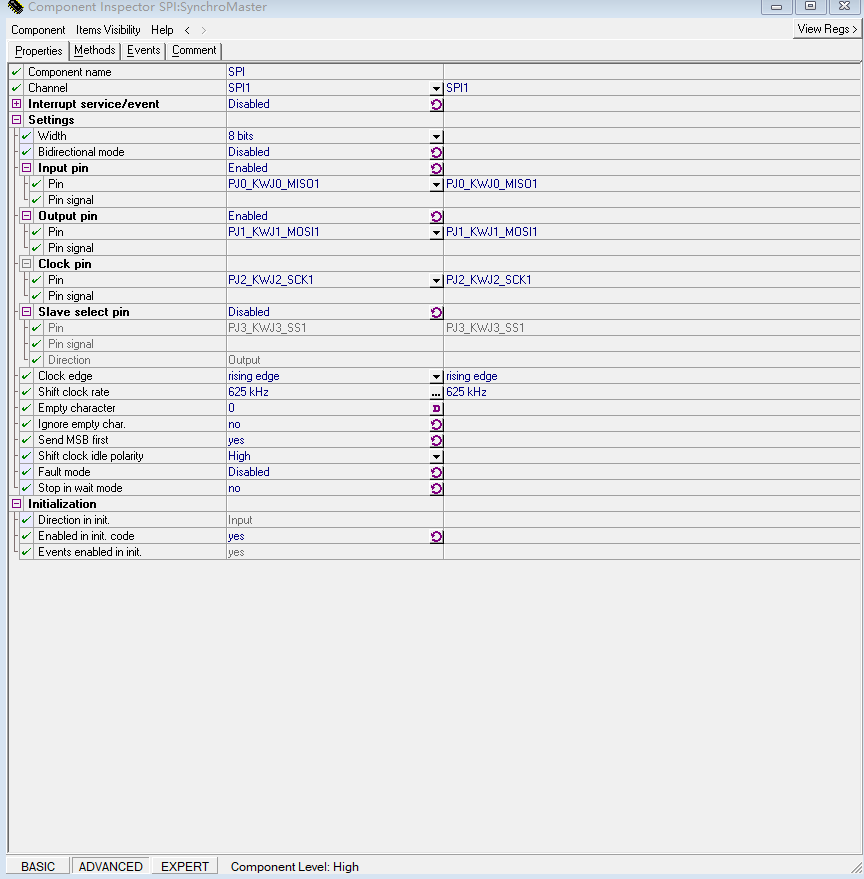
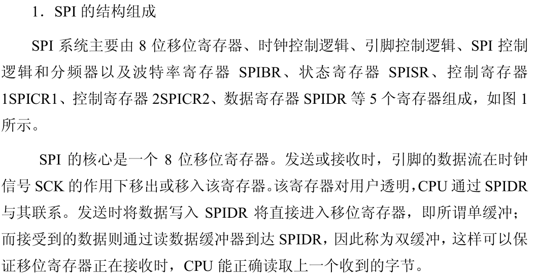
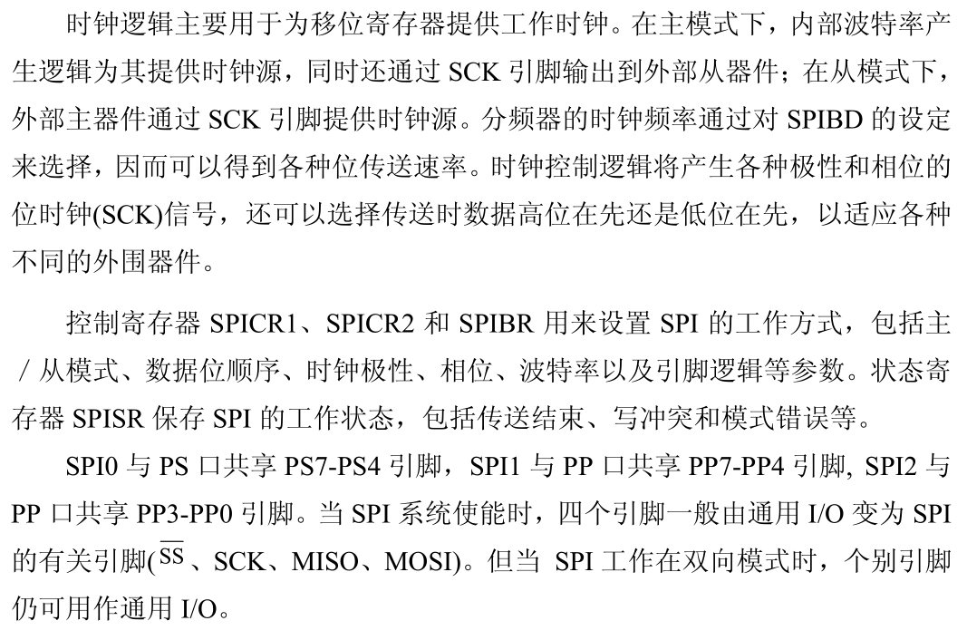
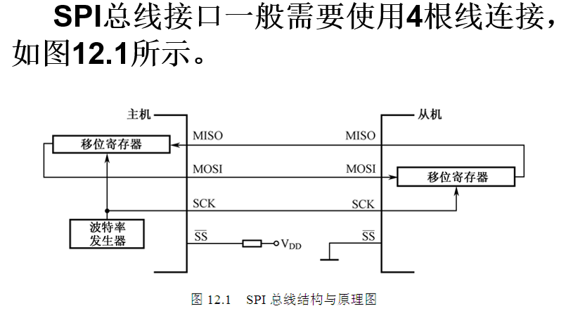
}2.10 SPI配置
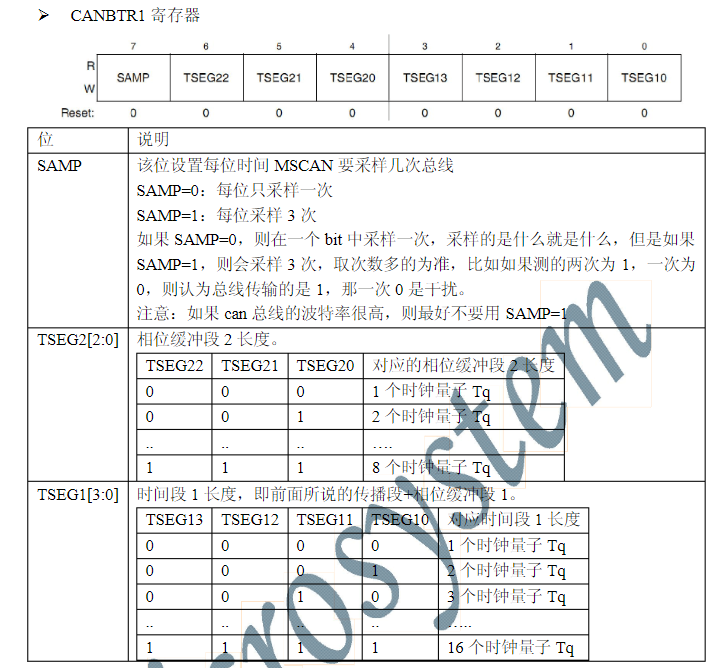
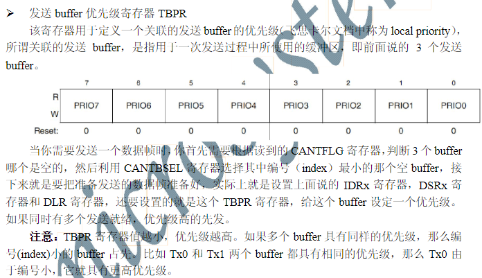
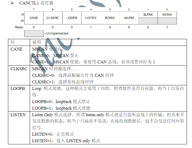
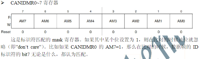
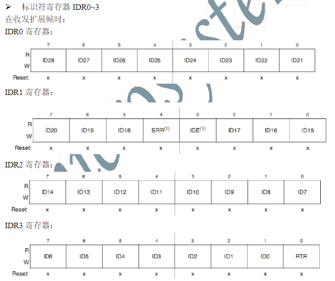
2.11 CAN配置
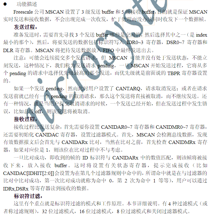


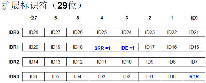
绿色的'x'为移动后空出的位
整理下为:1000 0111 110x x000 0010 0001 0011 001x
空出的位,根据帧类型填就行,也可随便填,我们CANIDMR的值,在该位取1,不关心该为就好了;
例如我们需要过滤出扩展帧0x10F81099;
则根据上面的,得出AR值为: 1000 0111 110x x000 0010 0001 0011 001x,把x取1,则为
1000 0111 1101 1000 0010 0001 0011 0011 即AR寄存器值为 0x87D82133 ,那么MR值只把SRR,IDE,RTR位取1
0000 0000 0001 1000 0000 0000 0000 0001 即MR寄存器值为 0x00180001 ,这样就能过滤出扩展帧ID0xF81099
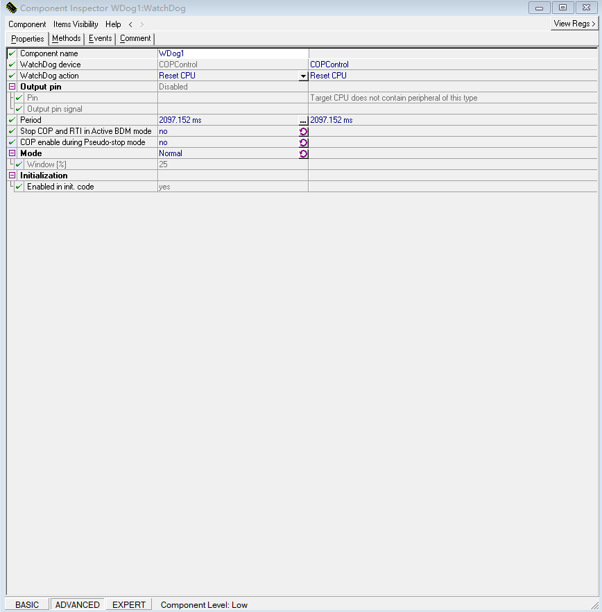
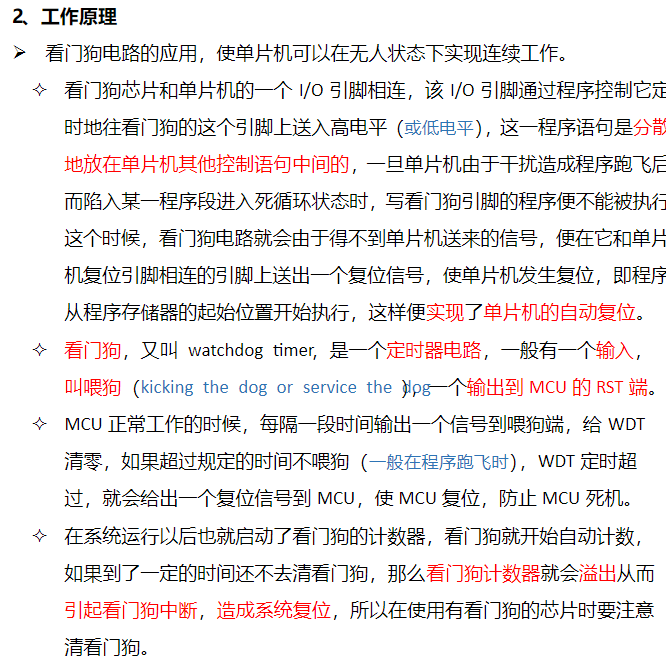
2.12 看门狗配置