本文档详细介绍利用三层交换机实现 VLAN 间路由,文内含长段代码可复制可往左滑,希望对大家有帮助!
实验背景
某企业有两个主要部门,技术部和销售部,分处于不同的办公室,为了安全和便于管理对两个部门的主机进行了 VLAN 的划分,技术部和销售部分处于不同的VLAN,先由于业务的需求需要销售部和技术部的主机能够相互访问,获得相应的资源,两个部门的交换机通过一台三层交换机进行了连接。
技术原理
三层交换机具备网络层的功能,实现 VLAN 相互访问的原理是:利用三层交换机的路由功能,通过识别数据包的 IP 地址,查找路由表进行选路转发,三层交换机利用直连路由可以实现不同 VLAN 之间的相互访问。三层交换机给接口配置 IP 地址。采用 SVI(交换虚拟接口)的方式实现 VLAN 间互连。SVI 是指为交换机中的VLAN 创建虚拟接口,并且配置 IP 地址。Tag VLAN是基于交换机端口的一种类型,主要用于使交换机的相同Vlan内的主机之间可以直接访问,同时对于不同Vlan的主机进行隔离。trunk主要用在连接其它交换机,以便在线路上承载多个vlanWLAN是Wireless Local Area Network的简称,指应用无线通信技术将计算机设备互联起来,构成可以互相通信和实现资源共享的网络体系。802.1x协议是WLAN第二代的认证技术,它是基于客户端-服务器(Client-Server)结构的访问控制和认证协议。它可以限制未经授权的用户/设备通过接入端口(Access Port)访问LAN/WLAN。DOT1Q是提供VLAN识别和服务质量(QoS)级别的IEEE标准。电气和电子工程师协会(IEEE,全称是Institute of Electrical and Electronics Engineers)是一个美国的电子技术与信息科学工程师的协会,是世界上最大的非营利性专业技术学会。ip routing 启用IP路由功能no ip routing 关闭IP路由功能
二层交换机与三层交换机区别
我们习惯说,在二层网络环境中相同vlan之间可以通信,不同vlan之间不可以通信,如果想通信必须借助三层设备,所以说三层交换机必须要做的事情是路由转发,但是二、三层交换机具体有什么区别呢?二层交换机工作于OSI模型的第2层(数据链路层),故而称为二层交换机。二层交换技术发展比较成熟,二层交换机属数据链路层设备,可以识别数据包中的MAC地址信息,根据MAC地址进行转发,并将这些MAC地址与对应的端口记录在自己内部的一个地址表中。具体的工作流程如下:(1) 当交换机从某个端口收到一个数据包,它先读取包头中的源MAC地址,这样它就知道源MAC地址的机器是连在哪个端口上的;(2) 再去读取包头中的目的MAC地址,并在地址表中查找相应的端口;(3) 如表中有与这目的MAC地址对应的端口,把数据包直接复制到这端口上;(4) 如表中找不到相应的端口则把数据包广播到所有端口上,当目的机器对源机器回应时,交换机又可以学习一目的MAC地址与哪个端口对应,在下次传送数据时就不再需要对所有端口进行广播了。不断的循环这个过程,对于全网的MAC地址信息都可以学习到,二层交换机就是这样建立和维护它自己的地址表。二层交换技术从网桥发展到VLAN(虚拟局域网),在局域网建设和改造中得到了广泛的应用。第二层交换技术是工作在OSI七层网络模型中的第二层,即数据链路层。它按照所接收到数据包的目的MAC地址来进行转发,对于网络层或者高层协议来说是透明的。它不处理网络层的IP地址,不处理高层协议的诸如TCP、UDP的端口地址,它只需要数据包的物理地址即MAC地址,数据交换是靠硬件来实现的,其速度相当快,这是二层交换的一个显著的优点。但是,它不能处理不同IP子网之间的数据交换。传统的路由器可以处理大量的跨越IP子网的数据包,但是它的转发效率比二层低,因此要想利用二层转发效率高这一优点,又要处理三层IP数据包,三层交换技术就诞生了。三层交换(也称多层交换技术,或IP交换技术)是相对于传统交换概念而提出的。众所周知,传统的交换技术是在OSI网络标准模型中的第二层——数据链路层进行操作的,而三层交换技术是在网络模型中的第三层实现了数据包的高速转发。简单地说,三层交换技术就是:二层交换技术+三层转发技术。三层交换机就是具有部分路由器功能的交换机。三层交换机的最重要目的是加快大型局域网内部的数据交换,所具有的路由功能也是为这目的服务的,能够做到一次路由,多次转发。对于数据包转发等规律性的过程由硬件高速实现,而像路由信息更新、路由表维护、路由计算、路由确定等功能,由软件实现。三层交换技术就是二层交换技术+三层转发技术。三层交换技术的出现,解决了局域网中网段划分之后,网段中子网必须依赖路由器进行管理的局面,解决了传统路由器低速、复杂所造成的网络瓶颈问题。
实验步骤
新建 packet tracer 拓扑图
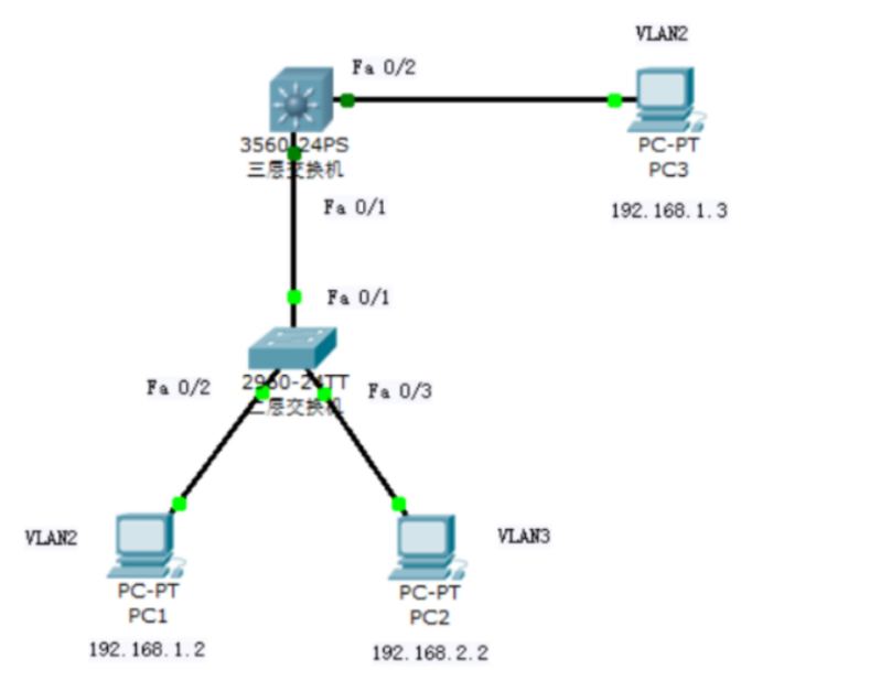
(1)在二层交换机上配置 VLAN2、VLAN3,分别将端口 2、端口 3 划分给 VLAN2、
VLAN3。
(2)将二层交换机与三层交换机相连的端口 fa 0/1 都定义为 tag Vlan 模式。
(3)在三层交换机上配置 VLAN2、VLAN3,此时验证二层交换机 VLAN2、VLAN3
下的主机之间不能相互通信。
(4)设置三层交换机 VLAN 间的通信,创建 VLAN2,VLAN3 的虚接口,并配置
虚接口 VLAN2、VLAN3 的 IP 地址。
(5)查看三层交换机路由表。
(6)将二层交换机 VLAN2、VLAN3 下的主机默认网关分别设置为相应虚拟接口
的 IP 地址。
(7)验证二层交换机 VLAN2,VALN3 下的主机之间可以相互通信。
实验设备
Switch_2960 1 台;Swithc_3560 1 台;PC 3 台;直连线
PC1
IP: 192.168.1.2
Submark: 255.255.255.0
Gateway: 192.168.1.1
PC2
IP: 192.168.2.2
Submark: 255.255.255.0
Gateway: 192.168.2.1
PC3
IP: 192.168.1.3
Submark: 255.255.255.0
Gateway: 192.168.1.1

S2960

en
conf t
vlan 2
exit
vlan 3
exit
int fa 0/2
switchport access vlan 2
int fa 0/3
switchport access vlan 3
int fa 0/1
switchport mode trunk
end
show vlan

S3560

en
conf t
vlan 2
exit
vlan 3
exit
int fa 0/1
switchport trunk encapsulation dot1q #将0/1端口封装成dot1q协议
switchport mode trunk
exit
int fa 0/2
switchport access vlan 2
exit
interface vlan 2
ip address 192.168.1.1 255.255.255.0
no shutdown
exit
interface vlan 3
ip address 192.168.2.1 255.255.255.0
no shutdown
exit
ip routing
exit
show ip route
show vlan
PC3 Ping PC1
Ping 192.168.1.2
PC3 Ping PC2

Ping 192.168.1.3
<以上代码可复制粘贴,可往左滑>
实战演练
二层交换机
Switch>en
Switch#conf t
Enter configuration commands, one per line. End with CNTL/Z.
Switch(config)#vlan 2
Switch(config-vlan)#exit
Switch(config)#vlan 3
Switch(config-vlan)#int fa 0/2
Switch(config-if)#switchport access vlan 2
Switch(config-if)#int fa 0/3
Switch(config-if)#switchport access vlan 3
Switch(config-if)#int fa 0/1
Switch(config-if)#switchport mode trunk

%LINEPROTO-5-UPDOWN: Line protocol on Interface FastEthernet0/1, changed state to down

%LINEPROTO-5-UPDOWN: Line protocol on Interface FastEthernet0/1, changed state to up

Switch(config-if)#end
Switch#
%SYS-5-CONFIG_I: Configured from console by console

Switch#show vlan

VLAN Name Status Ports
---- -------------------------------- --------- -------------------------------
1 default active Fa0/4, Fa0/5, Fa0/6, Fa0/7
Fa0/8, Fa0/9, Fa0/10, Fa0/11
Fa0/12, Fa0/13, Fa0/14, Fa0/15
Fa0/16, Fa0/17, Fa0/18, Fa0/19
Fa0/20, Fa0/21, Fa0/22, Fa0/23
Fa0/24, Gig1/1, Gig1/2
2 VLAN0002 active Fa0/2
3 VLAN0003 active Fa0/3
1002 fddi-default act/unsup
1003 token-ring-default act/unsup
1004 fddinet-default act/unsup
1005 trnet-default act/unsup

VLAN Type SAID MTU Parent RingNo BridgeNo Stp BrdgMode Trans1 Trans2
---- ----- ---------- ----- ------ ------ -------- ---- -------- ------ ------
1 enet 100001 1500 - - - - - 0 0
2 enet 100002 1500 - - - - - 0 0
3 enet 100003 1500 - - - - - 0 0
1002 fddi 101002 1500 - - - - - 0 0
--More--

三层交换机
Switch>en
Switch#conf t
Enter configuration commands, one per line. End with CNTL/Z.
Switch(config)#vlan 2
Switch(config-vlan)#exit
Switch(config)#vlan 3
Switch(config-vlan)#exit
Switch(config)#int fa 0/1
Switch(config-if)#switchport trunk encapsulation dot1q
Switch(config-if)#switchport mode trunk
Switch(config-if)#switchport trunk allowed vlan 2,3
Switch(config-if)#exit
Switch(config)#int fa 0/2
Switch(config-if)#switchport access vlan 2
Switch(config-if)#exit
Switch(config)#int vlan 2

%LINK-5-CHANGED: Interface Vlan2, changed state to up

%LINEPROTO-5-UPDOWN: Line protocol on Interface Vlan2, changed state to up
Switch(config-if)#ip address 192.168.1.1 255.255.255.0
Switch(config-if)#no shutdown
Switch(config-if)#exit
Switch(config)#int vlan 3

%LINK-5-CHANGED: Interface Vlan3, changed state to up

%LINEPROTO-5-UPDOWN: Line protocol on Interface Vlan3, changed state to up
Switch(config-if)#ip address 192.168.2.1 255.255.255.0
Switch(config-if)#no shutdown
Switch(config-if)#exit
Switch(config)#ip routing
Switch(config)#exit
Switch#
%SYS-5-CONFIG_I: Configured from console by console

Switch#show ip route
Codes: C - connected, S - static, I - IGRP, R - RIP, M - mobile, B - BGP
D - EIGRP, EX - EIGRP external, O - OSPF, IA - OSPF inter area
N1 - OSPF NSSA external type 1, N2 - OSPF NSSA external type 2
E1 - OSPF external type 1, E2 - OSPF external type 2, E - EGP
i - IS-IS, L1 - IS-IS level-1, L2 - IS-IS level-2, ia - IS-IS inter area
* - candidate default, U - per-user static route, o - ODR
P - periodic downloaded static route

Gateway of last resort is not set

C 192.168.1.0/24 is directly connected, Vlan2
C 192.168.2.0/24 is directly connected, Vlan3
Switch#show vlan

VLAN Name Status Ports
---- -------------------------------- --------- -------------------------------
1 default active Fa0/3, Fa0/4, Fa0/5, Fa0/6
Fa0/7, Fa0/8, Fa0/9, Fa0/10
Fa0/11, Fa0/12, Fa0/13, Fa0/14
Fa0/15, Fa0/16, Fa0/17, Fa0/18
Fa0/19, Fa0/20, Fa0/21, Fa0/22
Fa0/23, Fa0/24, Gig0/1, Gig0/2
2 VLAN0002 active Fa0/2
3 VLAN0003 active
1002 fddi-default act/unsup
1003 token-ring-default act/unsup
1004 fddinet-default act/unsup
1005 trnet-default act/unsup

VLAN Type SAID MTU Parent RingNo BridgeNo Stp BrdgMode Trans1 Trans2
---- ----- ---------- ----- ------ ------ -------- ---- -------- ------ ------
1 enet 100001 1500 - - - - - 0 0
2 enet 100002 1500 - - - - - 0 0
3 enet 100003 1500 - - - - - 0 0
1002 fddi 101002 1500 - - - - - 0 0
--More--
<以上代码可复制粘贴,可往左滑>
测试
PC1 分别 ping PC2 和 PC3

PC>ipconfig

IP Address......................: 192.168.1.2
Subnet Mask.....................: 255.255.255.0
Default Gateway.................: 192.168.1.1

PC>ping 192.168.2.2

Pinging 192.168.2.2 with 32 bytes of data:

Request timed out.
Reply from 192.168.2.2: bytes=32 time=25ms TTL=127
Reply from 192.168.2.2: bytes=32 time=20ms TTL=127
Reply from 192.168.2.2: bytes=32 time=20ms TTL=127

Ping statistics for 192.168.2.2:
Packets: Sent = 4, Received = 3, Lost = 1 (25% loss),
Approximate round trip times in milli-seconds:
Minimum = 20ms, Maximum = 25ms, Average = 21ms

PC>ping 192.168.2.2

Pinging 192.168.2.2 with 32 bytes of data:

Reply from 192.168.2.2: bytes=32 time=18ms TTL=127
Reply from 192.168.2.2: bytes=32 time=23ms TTL=127
Reply from 192.168.2.2: bytes=32 time=19ms TTL=127
Reply from 192.168.2.2: bytes=32 time=22ms TTL=127

Ping statistics for 192.168.2.2:
Packets: Sent = 4, Received = 4, Lost = 0 (0% loss),
Approximate round trip times in milli-seconds:
Minimum = 18ms, Maximum = 23ms, Average = 20ms

PC>ping 192.168.1.3

Pinging 192.168.1.3 with 32 bytes of data:

Reply from 192.168.1.3: bytes=32 time=15ms TTL=128
Reply from 192.168.1.3: bytes=32 time=19ms TTL=128
Reply from 192.168.1.3: bytes=32 time=15ms TTL=128
Reply from 192.168.1.3: bytes=32 time=14ms TTL=128

Ping statistics for 192.168.1.3:
Packets: Sent = 4, Received = 4, Lost = 0 (0% loss),
Approximate round trip times in milli-seconds:
Minimum = 14ms, Maximum = 19ms, Average = 15ms

PC2 分别 ping PC1 和 PC3

PC>ipconfig

IP Address......................: 192.168.2.2
Subnet Mask.....................: 255.255.255.0
Default Gateway.................: 192.168.2.1

PC>ping 192.168.1.2

Pinging 192.168.1.2 with 32 bytes of data:

Reply from 192.168.1.2: bytes=32 time=24ms TTL=127
Reply from 192.168.1.2: bytes=32 time=23ms TTL=127
Reply from 192.168.1.2: bytes=32 time=24ms TTL=127
Reply from 192.168.1.2: bytes=32 time=20ms TTL=127

Ping statistics for 192.168.1.2:
Packets: Sent = 4, Received = 4, Lost = 0 (0% loss),
Approximate round trip times in milli-seconds:
Minimum = 20ms, Maximum = 24ms, Average = 22ms

PC>ping 192.168.1.3

Pinging 192.168.1.3 with 32 bytes of data:

Reply from 192.168.1.3: bytes=32 time=13ms TTL=127
Reply from 192.168.1.3: bytes=32 time=17ms TTL=127
Reply from 192.168.1.3: bytes=32 time=19ms TTL=127
Reply from 192.168.1.3: bytes=32 time=19ms TTL=127

Ping statistics for 192.168.1.3:
Packets: Sent = 4, Received = 4, Lost = 0 (0% loss),
Approximate round trip times in milli-seconds:
Minimum = 13ms, Maximum = 19ms, Average = 17ms

PC3 分别 ping PC1 和 PC2

PC>ipconfig

IP Address......................: 192.168.1.3
Subnet Mask.....................: 255.255.255.0
Default Gateway.................: 192.168.1.1

PC>ping 192.168.1.2

Pinging 192.168.1.2 with 32 bytes of data:

Reply from 192.168.1.2: bytes=32 time=14ms TTL=128
Reply from 192.168.1.2: bytes=32 time=17ms TTL=128
Reply from 192.168.1.2: bytes=32 time=17ms TTL=128
Reply from 192.168.1.2: bytes=32 time=16ms TTL=128

Ping statistics for 192.168.1.2:
Packets: Sent = 4, Received = 4, Lost = 0 (0% loss),
Approximate round trip times in milli-seconds:
Minimum = 14ms, Maximum = 17ms, Average = 16ms

PC>ping 192.168.2.2

Pinging 192.168.2.2 with 32 bytes of data:

Request timed out.
Reply from 192.168.2.2: bytes=32 time=17ms TTL=127
Reply from 192.168.2.2: bytes=32 time=16ms TTL=127
Reply from 192.168.2.2: bytes=32 time=18ms TTL=127

Ping statistics for 192.168.2.2:
Packets: Sent = 4, Received = 3, Lost = 1 (25% loss),
Approximate round trip times in milli-seconds:
Minimum = 16ms, Maximum = 18ms, Average = 17ms

PC>ping 192.168.2.2

Pinging 192.168.2.2 with 32 bytes of data:

Reply from 192.168.2.2: bytes=32 time=15ms TTL=127
Reply from 192.168.2.2: bytes=32 time=17ms TTL=127
Reply from 192.168.2.2: bytes=32 time=14ms TTL=127
Reply from 192.168.2.2: bytes=32 time=11ms TTL=127

Ping statistics for 192.168.2.2:
Packets: Sent = 4, Received = 4, Lost = 0 (0% loss),
Approximate round trip times in milli-seconds:
Minimum = 11ms, Maximum = 17ms, Average = 14ms
<以上代码可复制粘贴,可往左滑>