背景
[作者:DeepLearningStack,阿里巴巴算法工程师,开源TensorFlow Contributor]
欢迎大家关注我的公众号,“互联网西门二少”,我将继续输出我的技术干货~

在经过TensorFlow的Placer策略模块调整之后,下一步就是根据Placement信息对Graph做切割,然后分发到不同的Device上去执行的过程了。在对Graph做切割时,为了保证跨Device执行的逻辑与切割前一致并保证原图中Node节点之间的依赖关系不受到破坏,不但需要插入Send、Recv通信节点对,还需要维护相对复杂的Control Edge。这些功能被设计在了TensorFlow的Graph Partitioner模块中。从该模块的代码量和原理上看,其内容非常好理解,但在涉及到对含有while_loop、loop_contition、exit、enter、merge、switch等Control Flow Op的图做切割时,其处理就显得相对复杂。本篇主要介绍Graph Partitioner的整体过程和相关源码,但考虑到Control Flow Op相关的处理还需要一些前置知识,而这些前置知识在TensorFlow源码阅读与架构梳理系列中尚未完成书写,因此本篇暂时过滤掉对Control Flow Op相关逻辑的处理。
功能描述
顾名思义,Graph Partitioner是用来根据每个节点的Placement信息对原图做切割的,它主要包括三个核心步骤:
1. 对原图的Placement信息做划分,产生多个子图Sub graph;
2. 为具有跨Device依赖的节点对插入Send类和Recv类节点对;
3. 插入必要的Control Edge
一个完成了图切割的Graph可以在多个机器的分布式集群环境中执行,但是应当注意到在单机单卡时这一步骤也是必要的,因为TensorFlow是个异构框架,单机单卡也涉及到GPU和CPU之间的图切割。图切割的依据是Placement信息,如果想深入了解Placement模块相关内容,请参考本系列的这篇文章——《TensorFlow中的Placement启发式算法模块——Placer》。
Graph Partitioner模块十分通用,在单机单卡运行过程中,DirectSession会让Graph Partitioner根据不同的Device进行切割。而在分布式运行过程中,Graph Partitioner会被执行两次,一次是SplitByWorker,另一次是SplitByDevice。
Graph Partition切割流程
为了描述方便,特意将图切割过程分为以下几个子过程,整体流程如下图所示,图右边的文字是对每个过程的简短描述,本篇我们重点阐述标记为深色的子过程。
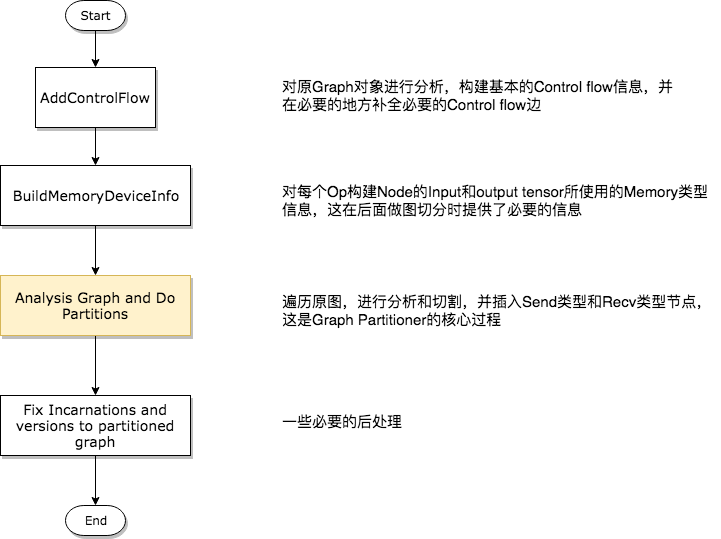
第一步——分析构建Control Flow相关信息
这个过程在代码中是通过AddControlFlow函数实现的,由于改代码深度依赖于Control Flow Op的相关模块,且对于不含有Control Flow Op的Graph几乎什么都没有做,因此我们先忽略这个过程,等到对Control Flow模块做详细解读时再回过头来研究其在Graph Partitioner中的意义。
 1 GraphInfo g_info;
 2 if (!opts.control_flow_added) {
 3   // Add the "code" for distributed execution of control flow. Code is
 4   // added only for the frames that are placed on multiple devices. The
 5   // new graph is an equivalent transformation of the original graph and
 6   // has the property that it can be subsequently partitioned arbitrarily
 7   // (down to the level of individual device) for distributed execution.
 8   status = AddControlFlow(opts, g, &g_info);
 9   if (!status.ok()) return status;
10 }
第二步——构建Op的Input和Output Memory类型信息
在介绍这个过程之前,首先需要明确两种概念,他们是DeviceMemory和HostMemory。前者指的是计算设备的Memory类型,后者指的是CPU的Memory类型,它们在TensorFlow中被定义为Enum类型,代码如下所示。
1 // MemoryType is used to describe whether input or output Tensors of
2 // an OpKernel should reside in "Host memory" (e.g., CPU memory) or
3 // "Device" Memory (CPU memory for CPU devices, GPU memory for GPU
4 // devices).
5 enum MemoryType {
6   DEVICE_MEMORY = 0,
7   HOST_MEMORY = 1,
8 };
对Op的Input和Output Memory信息进行检索并构建缓存的函数是BuildMemoryDeviceInfo,该过程构建的信息对后面真正做图切割非常重要。因为TensorFlow的Op在注册时需要不但需要指定其在各个Device上的实现版本(比如CPU版本的Op和GPU版本的Op都是分别注册到系统中的),还需要指出其Input和Output Tensor的类型以及所使用的Memory类型,即使某个Op存在GPU上的实现,它的GPU版本也有可能需要在CPU上读入数据或输出结果。例如,GPU版本的Reshape Op注册代码如下。
 1 #define REGISTER_GPU_KERNEL(type)
 2   REGISTER_KERNEL_BUILDER(Name("Reshape")
 3                               .Device(DEVICE_GPU)
 4                               .HostMemory("shape")
 5                               .TypeConstraint<type>("T")
 6                               .TypeConstraint<int32>("Tshape"),
 7                           ReshapeOp);
 8   REGISTER_KERNEL_BUILDER(Name("Reshape")
 9                               .Device(DEVICE_GPU)
10                               .HostMemory("shape")
11                               .TypeConstraint<type>("T")
12                               .TypeConstraint<int64>("Tshape"),
13                           ReshapeOp);
上面的宏显示,虽然Reshape Op确实在GPU上有注册的实现版本,但是它依然要使用HostMemory。另外,某些Tensor的类型也决定了其是否可以被放置到Device Memory上,一般情况下float类型的数据对于计算设备是非常友好的,而String类型就不是这样,所以在types.cc文件中规定了一些强制被放在HostMemory的数据类型,如下代码所示。
 1 bool DataTypeAlwaysOnHost(DataType dt) {
 2   // Includes DT_STRING and DT_RESOURCE.
 3   switch (dt) {
 4     case DT_STRING:
 5     case DT_STRING_REF:
 6     case DT_RESOURCE:
 7       return true;
 8     default:
 9       return false;
10   }
11 }
TensorFlow的设计哲学认为,参与计算的Tensor应该被放在DeviceMemory上,而参与控制的Tensor应该放在HostMemory上。这样的设计思路虽然有一定道理,但也确实对一些case产生了负面的性能影响。在后面的过程中我们可以看到,Partition过程会根据每个Op的Input和Output Memory类型决定是否插入Send类和Recv类节点对,因此会经常遇到处于同一个Device上的两个节点也需要插入Send类和Recv类节点对的情况,显然这有可能带来性能下降。
第三步——对原图进行分析,并产出切割后的多个子图
在面两个步骤的准备工作完成之后,就可以进行图切割和Send类、Recv类节点对的插入,以及Control Edge的插入了,这个过程如下图所示。因为流程图绘制的比较简洁,我们将在下面对该图进行详细说明。
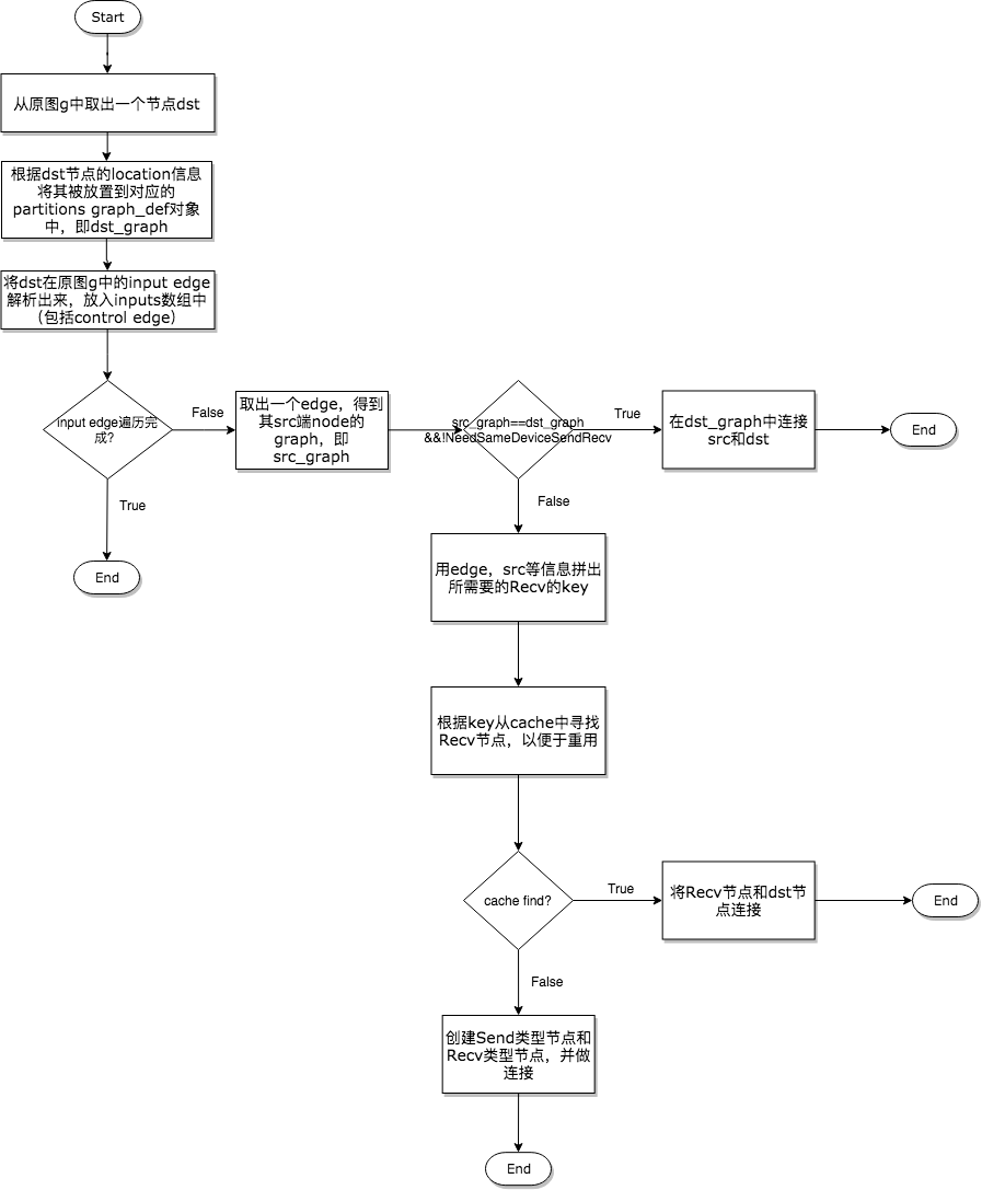
1.将原图中取出一个节点dst,根据其Device将其分配到对应的Sub Graph中,然后以dst节点为终点节点,沿着其接收Tensor的方向向输入节点src进行分析;
2.Node之间的连接依靠的是Edge,因此对于dst来说需要根据其Input的Edge来分析src节点的位置,所以这里要获得dst的所有Input Edge;
3.在逐个遍历分析Input Edge时,第一个要处理的就是src和dst处于同一个Device,但依然需要插入Send类和Recv类节点对的情况。根据第二步BuildMemoryDeviceInfo提供的信息,某些Op的注册和特殊之处确实会得到这种情况;
4.如果决定需要插入Send类和Recv类节点对,那么优先考虑是否可以重用Recv节点,如果根据信息拼出的Key能够在缓存中搜索到该Recv Node,那么则取出重用。这种Recv Fusion是一种性能优化手段,能避免多次不必要的通信,真正做到达到一次通信多次使用的目的,下面的代码展示了这一个过程;
 1       // Check whether there is already a send/recv pair transferring
 2       // the same tensor/control from the src to dst partition.
 3       const bool on_host = IsDstInputOnHost(edge, g_info);
 4       DupRecvKey key{src->id(), edge->src_output(), dst_graph, on_host};
 5       auto iter = dup_recv.find(key);
 6       if (iter != dup_recv.end()) {
 7         // We found one. Reuse the data/control transferred already.
 8         const string& recv_node_name = iter->second.recv->name();
 9         if (edge->IsControlEdge()) {
10           AddInput(dst_def, recv_node_name, Graph::kControlSlot);
11         } else {
12           AddInput(dst_def, recv_node_name, 0);
13         }
14         ref_control_inputs.push_back(recv_node_name);
15
16         // We want the start_time for the recv to be the smallest of the start
17         // times of it's consumers. So we update this whenever we use a recv,
18         // and write it out to the attribute at the end of the subroutine
19         if (iter->second.start_time > recv_start_time) {
20           iter->second.start_time = recv_start_time;
21         }
22         continue;
23       }
5.如果缓存中没有找到可重用的节点,那么只能创建新的Send类和Recv类节点对了。插入通信节点对时需要考虑多种情况,有时插入Send和Recv节点就能完成任务,有时还需要插入Control Edge以保证依赖顺序,有时甚至还要插入一些其他的辅助节点。事实上,分成这三种逻辑处理已经覆盖任何情况了,后面一章将详细阐述这三种处理逻辑。
第四步——必要的后处理
这是一些收尾的工作,过程非常简单,比如完善Send和Recv节点的Incarnation信息,补全各个子图的version信息等,代码如下所示。
 1   const FunctionLibraryDefinition* flib_def = opts.flib_def;
 2   if (flib_def == nullptr) {
 3     flib_def = &g->flib_def();
 4   }
 5
 6   // Set versions, function library and send/recv incarnation.
 7   for (auto& it : *partitions) {
 8     GraphDef* gdef = &it.second;
 9     *gdef->mutable_versions() = g->versions();
10     // Prune unreachable functions from `flib_def` before adding them to `gdef`.
11     *gdef->mutable_library() = flib_def->ReachableDefinitions(*gdef).ToProto();
12
13     // Traverse the graph to fill every send/recv op's incarnation
14     // information.
15     SetIncarnation(opts, gdef);
16   }
Send和Recv节点对插入的三种情况
在代码中,声明插入Send和Recv节点的代码段非常简单,如下所示。
 1       // Need to split edge by placing matching send/recv nodes on
 2       // the src/dst sides of the edge.
 3       NodeDef* send = AddSend(opts, g_info, src_graph, edge, send_from,
 4                               send_start_time, &status);
 5       if (!status.ok()) return status;
 6
 7       NodeDef* real_recv = nullptr;
 8       NodeDef* recv =
 9           AddRecv(opts, g_info, dst_graph, edge, &real_recv, &status);
10       if (!status.ok()) return status;
但是对于不同的情况却有着丰富的处理逻辑,所以下面在展示示意图的同时,会将相关的代码段摘出来做展示。
在同一个Device上插入Send和Recv节点对
因为同一个Device上的Send和Recv节点在执行过程中实际上Memory Copy,而Recv的kernel又是异步的,所以需要有一种机制保证保证Recv一定要在Send之后执行,因此需要在Send和Recv之间插入一个Control Edge,从图的依赖上保证它们的执行顺序。
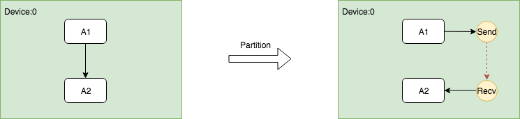
这个过程的关键是在插入Send和Recv节点之后,需要插入额外的Control Edge,代码如下。
// Fix up the control flow edge.
// NOTE(yuanbyu): 'real_recv' must be the real recv node.
if (src_graph == dst_graph) {
  // For same device send/recv, add a control edge from send to recv.
  // This prevents the asynchronous recv kernel from being scheduled
  // before the data is available.
  AddInput(real_recv, send->name(), Graph::kControlSlot);
}
跨Device根据DataFlow插入Send和Recv节点对
这是最容易理解的一种情况,Send节点需要插入到和src节点相同的Device上,Recv需要插入到和dst节点相同的Device上。并且为了减少不必要的通信开销,尽可能的重用Recv节点。
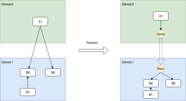
该过程的关键在于复用Recv节点,前面在获取缓存时已经阐述过,这里不重复展示。
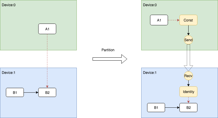
跨Device根据ControlFlow插入Send和Recv节点对
当存在跨Device的Control Flow依赖时,问题变得相对复杂。因为Control Edge只是用作控制,它并不传输真正的Tensor,但在跨Device的情况下,必须要向dst所在的Device发送消息,让其知晓存在依赖控制。TensorFlow选择发送DummyConst的方式通知dst节点,具体而言,需要在src的Device上插入shape为0的DummyConst节点,然后将其作为Send的唯一输入,并将src节点作为它的Control Dependncy。另一方面,在dst的Device上插入Recv节点之后,还需要插入一个identity节点负责读取发送来的DummyConst,然后将Indentity作为dst的Control Dependency。如此一来,这种跨Device的依赖关系就可以被完全等价的表示出来。
这个过程的关键在于src端的DummyConst插入和dst端的Identity插入,这两部分的逻辑处理写在了两个地方。DummyConst和相关控制依赖的代码如下。
 1       NodeDefBuilder::NodeOut send_from;
 2       if (edge->IsControlEdge()) {
 3         // Insert a dummy const node that will generate a tiny
 4         // data element to be sent from send to recv.
 5         VLOG(1) << "Send/Recv control: " << src->assigned_device_name() << "["
 6                 << src->name() << "] -> " << dst->assigned_device_name() << "["
 7                 << dst->name() << "]";
 8         NodeDef* dummy = AddDummyConst(opts, src_graph, edge, &status);
 9         if (!status.ok()) return status;
10         // Set the start time for this dummy node.
11         if (opts.scheduling_for_recvs) {
12           AddNodeAttr("_start_time", send_start_time, dummy);
13         }
14         AddInput(dummy, src->name(), Graph::kControlSlot);
15         send_from.Reset(dummy->name(), 0, DT_FLOAT);
16       } else {
17         send_from.Reset(src->name(), edge->src_output(), EdgeType(edge));
18       }
Indentity即相关依赖的插入逻辑被写在了AddRecv中,下面展示了这个片段。
 1   // Add the cast node (from cast_dtype to dtype) or an Identity node.
 2   if (dtype != cast_dtype) {
 3     const string cast_op = (host_memory) ? "_HostCast" : "Cast";
 4     NodeDefBuilder cast_builder(opts.new_name(src->name()), cast_op);
 5     cast_builder.Attr("DstT", dtype);
 6     cast_builder.Device(dst->assigned_device_name())
 7         .Input(recv->name(), 0, cast_dtype);
 8     NodeDef* cast = gdef->add_node();
 9     *status = cast_builder.Finalize(cast);
10     if (!status->ok()) return nullptr;
11     return cast;
12   } else if (edge->IsControlEdge()) {
13     // An Identity is only needed for control edges.
14     NodeDefBuilder id_builder(opts.new_name(src->name()), "Identity");
15     id_builder.Device(dst->assigned_device_name())
16         .Input(recv->name(), 0, cast_dtype);
17     NodeDef* id = gdef->add_node();
18     *status = id_builder.Finalize(id);
19     if (!status->ok()) return nullptr;
20     return id;
21   } else {
22     return recv;
23   }
关于使用bfloat16压缩通信
TensorFlow支持通过使用bfloat16减少通信量,虽然bfloat16理论上是有损精度的,但是大量的实践证明这个精度损失是基本感知不到的。bfloat16的通信功能可以通过以下配置项打开,只要在创建Session时传入打开该功能的config即可。
graph_options = tf.GraphOptions(enable_bfloat16_sendrecv=True)
session_config = tf.ConfigProto(gpu_options=gpu_options)
而TensorFlow在底层插入bfloat的转换节点就是在Graph Partitioner的AddSend函数和AddRecv函数中插入的,但是这个转换只会在跨Device的Send和Recv前后插入,这也非常符合逻辑,因为处于同一个Device的Send和Recv本质上是本地的Memory Copy,其带宽非常高,所以通信并不是瓶颈,而插入两个转换节点只能带来额外的转换开销。
总结
本文介绍了TensorFlow中的图切割模块——Graph Partitioner。考虑到Graph Partitioner在处理含有Control Flow Op的Graph时具有更加复杂的逻辑,而本系列尚未完成Control Flow模块的编写,因此在梳理源码时只对一般情况作了详细阐述。事实上,仅仅是这些内容也已经可以让读者对TensorFlow的图切割过程有了较好的理解。无论是SplitByDevice还是SplitByWorker,Graph Partitioner作为TensorFlow的图切割模块都具有良好的模块化通用化特点,它的关键点在于如何保证切割后的多个子图和原图具有完全的逻辑等价性。Graph Partitioner能够正常工作的前提是Graph中的每个Node都具有了Device Placement信息,因此在一次Run过程中,Graph Partitioner是在Placer模块完成之后才进行的。今后我们在梳理单机多卡和分布式执行引擎时,我们还会看到Placer和Graph Partitioner的身影,这也是本系列中多次强调其重要性的原因。