- What is PIC and what is it for?
- What is APIC and what is it for? What is the purpose of LAPIC and I/O APIC?
- What are the differences between APIC, xAPIC, and x2APIC?
- What is MSI? What are the differences between MSI and MSI-X?
- What is the role of the $PIR, MPtable, and ACPI tables?
If you want to know the answer for one of these questions, or if you simply want to know about interrupt controller evolution, please, welcome.
Introduction
For those who don't know what an interrupt is, here is a quote from Wikipedia:
In system programming, an interrupt is a signal to the processor emitted by hardware or software indicating an event that needs immediate attention. An interrupt alerts the processor to a high-priority condition requiring the interruption of the current code the processor is executing. The processor responds by suspending its current activities, saving its state, and executing a function called an interrupt handler (or an interrupt service routine, ISR) to deal with the event. This interruption is temporary, and, after the interrupt handler finishes, the processor resumes normal activities.
There are two types of interrupts: hardware interrupts and software interrupts (softirqs):
- Hardware interrupts are used by devices to communicate that they require attention from the operating system. Internally, hardware interrupts are implemented using electronic alerting signals that are sent to the processor from an external device, which is either a part of the computer itself, such as a disk controller, or an external peripheral. For example, pressing a key on the keyboard or moving the mouse triggers hardware interrupts that cause the processor to read the keystroke or mouse position. The act of initiating a hardware interrupt is referred to as an interrupt request (IRQ).
- A software interrupt is caused either by an exceptional condition in the processor itself, or a special instruction in the instruction set which causes an interrupt when it is executed. The former is often called a trap or exception and is used for errors or events occurring during program execution that are exceptional enough that they cannot be handled within the program itself. For example, a divide-by-zero exception will be thrown if the processor's arithmetic logic unit is commanded to divide a number by zero as this instruction is an error and impossible.
This article is about hardware/external interrupts IRQ.
What is the purpose of interrupts? For example, we want to perform an action with an incoming packet from the network card as soon as the packet arrives. If you don't want to continuously ask the network card «Has my packet arrived?» and waste your processor time, you can use external hardware interrupt IRQ. The interrupt line from a device should be connected to the INTR line of the CPU, and after each packet is received, the network card will make a signal over this line. The CPU will sense this signal and know that the network card has information for it. Only after that the CPU will read the incoming packet.
But what should we do if there are a lot of external devices? It would be very unproductive to make a ton of INTR pins on the CPU for all of them.
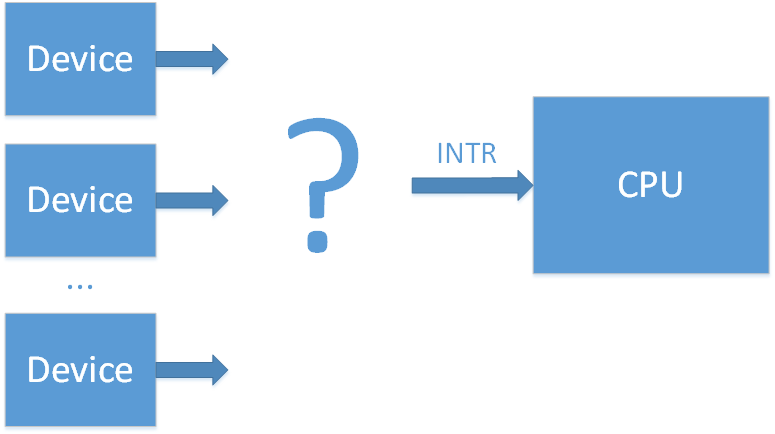
To solve this problem a special chip was invented — an interrupt controller.
PIC
(wiki/osdev)
The first interrupt controller chip was the Intel 8259 PIC. It had 8 input lines (IRQ0-7) and 1 output line (which connects the interrupt controller with the INTR line of the CPU). When there is an interrupt from one of the devices on its input lines, the 8259 will make a signal over the INTR line. After that the CPU will know that some device requires its immediate attention, and the processor will ask the PIC which of the 8 input lines (IRQx) was the source of this interrupt. There is some overhead to this polling, but now we have 8 interrupt lines instead of 1.

Soon 8 lines weren't enough. To increase the total number of interrupt lines two 8259 controllers (master and slave) were connected in a cascade (Dual PIC).
IRQs from 0 to 7 are processed with the first Intel 8259 PIC (master), and IRQs from 8 to 15 are processed with the second Intel 8259 PIC (slave). Only the master is connected to the CPU and can signal about the incoming interrupts. If there is an interrupt on lines 8-15, the second PIC (slave) will signal about it to the master on the line IRQ2, and after that the master will signal the CPU. This cascaded interrupt takes away 1 of the 16 lines, but makes a total of 15 interrupts for all external devices.

This scheme was adopted by the community, and now when someone talks about PIC (Programm Interrupt Controller) they mean this Dual PIC system. After some time the 8259 controllers were improved and got a new name: 8259A. With these controllers the DUAL PIC system was included in the chipset. At a time when the main bus for external device connection was the ISA, this system was sufficient. It was only necessary that different devices did not connect to the same IRQ line, since ISA interrupts aren't shareable.
The device interrupt mapping was pretty much standard:
Example (from here):
IRQ 0 — system timer
IRQ 1 — keyboard controller
IRQ 2 — cascade (interrupt from slave controller)
IRQ 3 — serial port COM2
IRQ 4 — serial port COM1
IRQ 5 — parallel port 2 and 3 or sound card
IRQ 6 — floppy controller
IRQ 7 — parallel port 1
IRQ 8 — RTC timer
IRQ 9 — ACPI
IRQ 10 — open/SCSI/NIC
IRQ 11 — open/SCSI/NIC
IRQ 12 — mouse controller
IRQ 13 — math co-processor
IRQ 14 — ATA channel 1
IRQ 15 — ATA channel 2
The configuration and work with 8259 chips is carried out with I/O ports:
| Chip | Register | I/O port |
|---|---|---|
| Master PIC | Command | 0x0020 |
| Master PIC | Data | 0x0021 |
| Slave PIC | Command | 0x00A0 |
| Slave PIC | Data | 0x00A1 |
Full documentation of the 8259A can be found here.
The PCI bus later replaced the ISA bus. Unfortunately, the number of devices began to exceed the number 15. Also instead of the static ISA bus, devices in the PCI bus can be added to the system dynamically which could potentially lead to even more problems. But luckily, interrupts in the PCI bus can be shared, so it is possible to connect many devices to one interrupt line IRQ. In the end, to solve the problem of lack of interrupt lines, it was decided to group interrupts from all of the PCI devices to PIRQ lines (Programmable Interrupt Request).
For example, suppose we have 4 free interrupt lines on the PIC controller and 20 PCI devices. We can combine interrupts from 5 devices into one PIRQx line, and connect these PIRQx lines to the PIC controller. In this case if there is an interrupt on one of PIRQx lines, the processor will have to ask all the devices connected to this line about the interrupt to know who is responsible for it, but in the end it solves the problem. The device that connects PCI interrupt lines to PIRQ lines is often called a PIR router.
With this method it is necessary to ensure that PIRQx lines don't connect to lines with ISA interrupts (since this will produce conflicts) and that PIRQx lines are balanced (the more devices we connect to one line, the more devices the CPU will need to poll when it needs to check which device is responsible for the interrupt).

Note: on the image the mapping of PCI device -> PIR is pictured abstractedly, since in the real case it is a little bit more complicated. In the real world each PCI device has 4 interrupt lines (INTA, INTB, INTC, INTD) and up to 8 functions, where each function can have only one of these INTx interrupts. Which INTx line will be used by each function is determined by the chipset configuration.
By their nature functions are separate logical blocks. For example, one PCI device can have an Smbus controller function, a SATA controller function, and an LPC bridge function. From the point of view of an operating system (OS), each function is like a separate device with its own configuration space (PCI config).
Information about a PIC controller interrupt routing is sent to the OS by the BIOS, with the help of the table $PIR and through the registers 3Ch (INT_LN Interrupt Line (R/W)) and 3Dh (INT_PN Interrupt Pin (RO)) of the PCI configuration space for each function.
A specification for the $PIR table was recently on the Microsoft website, but currently is unavailable. It is possible to understand the table's content from PCI BIOS Specification [4.2.2. Get PCI Interrupt Routing Options] or from here (the last link is in Russian, but you can try to google «PCI IRQ Routing Table Specification»)
APIC
(wiki, osdev)
The last method worked until multiprocessor systems arrived. By nature, the PIC can only send interrupts to one CPU, and in a multiprocessor system it is desired to load CPUs in a balanced way. The solution to this problem was the new APIC interface (Advanced PIC).
A special controller called LAPIC (Local APIC) was added for each processor, as well as the I/O APIC controller for routing interrupts from external devices. All of these controllers are combined in a common bus with the name APIC (note that modern systems use a standard system bus instead of a separate APIC bus for this task).
When an external interrupt arrives on the I/O APIC input, the controller will send an interrupt message to the LAPIC of one of the system CPUs. In this way the I/O APIC controller helps balance interrupt load between processors.
The first APIC chip was the 82489DX, which was a separate chip that had a connected LAPIC and I/O APIC within itself. For a dual processor system three such chips were needed: two for LAPIC and one for I/O APIC. Later LAPIC functionality was directly included in processors, and the I/O APIC part was separated to the 82093AA chip.
The I/O APIC 82093AA had 24 inputs, and the APIC architecture could support up to 16 CPUs. Interrupts 0-15 were left for old ISA interrupts for compatibility with older systems, and interrupts 16-23 were meant for all the PCI devices. With this delimitation all conflicts between ISA and PCI interrupts could be easily avoided. With the increased number of free interrupt lines it also became possible to increase the number of PIRQx lines.

I/O APIC and LAPIC programming is done with the help of MMIO. LAPIC registers are usually placed on address 0xFEE00000, and I/O APIC registers on address 0xFEС00000, though it is possible to reconfigure them.
As in the PIC case, separate chips in the beginning became part of the chipset later.
APIC architecture was later modernized, and its new variant was named xAPIC (x — extended). With full backwards compatibility, the total number of possible CPUs in system was increased to 256.
The next step in architecture development was named x2APIC. The number of possible CPUs in the system was increased to 2^32. These controllers can work in a backwards compatibility mode with xAPIC, or they can work in the new x2APIC mode. In this new mode controller programming is not done through MMIO, but through MSR registers (which are much faster). According to this link, IOMMU support is necessary for this mode.
It is worthwhile to note that it is possible to have several I/O APIC controllers in the system. For example, one for 24 interrupts in a southbridge and the other one for 32 interrupts in a northbridge. In the context of I/O APIC, interrupts are usually called GSI (Global System Interrupt). So, the forementioned system has GSIs 0-55.
How can we determine if a CPU has an internal LAPIC and which APIC architecture it supports? It is possible to answer these questions by inspecting bit-flags from CPUID.
To help the OS discover LAPIC and I/O APIC, the BIOS should present information about them either through an MPtable (old method) or through an ACPI table (a MADT table in this case). Besides common information, both the MPtable and the ACPI (in this case a DSDT table) should contain information about the interrupt routing. This means information about which device uses which interrupt line (similar to the $PIR table).
You can read about the MPtable in the official specification. Earlier the specification was on the Intel website, but currently it is only possible to find it in an archive version. The ACPI specification can be found on the UEFI website (current version is 6.2). It is worthwhile to notice that with ACPI it is possible to declare interrupt routing for systems without APIC (instead of providing a separate $PIR table).
MSI
(wiki)
The last variant of APIC was good, but not without downsides. All of the interrupt lines from devices made the system very complicated and thus increased error probability. The PCI express bus came to replace the PCI bus, which simplified all interrupt systems completely. It doesn't have interrupt lines at all. For backwards compatibility interrupt signals (INTx#) are emulated with a separate kind of messages. With PCI interrupt lines their connection was made with physical wires. With PCI express interrupt lines a connection is logical and is made by PCI express bridges. But this support of legacy INTx interrupts only exists for backwards compatibility with the PCI bus. PCI express introduces a completely new method of interrupt delivery — MSI (Message Signaled Interrupts). In this method a device signals about the interrupt simply by writing to a special place in the MMIO region of the CPUs LAPIC.

Earlier a single PCI device (this means all its functions) could have only 4 interrupts, but now it became possible to address up to 32 interrupts.
In the case of MSI there is no sharing of interrupt lines: every interrupt naturally corresponds to its device.
MSI interrupts also solve one more problem. For example, let's imagine a situation where a device makes a memory-write transaction, and wants to signal about its completion through the interrupt. But a write transaction can be delayed on the bus in the process of its transmission (and the device couldn't know about it). In this case the signal about the interrupt will come to the CPU first, so the processor will read not yet valid data. If MSI is used, information about the MSI is transmitted in the same way as data messages, and so it can't come earlier.
It is worthwhile to notice that MSI interrupts can't work without LAPIC, but MSI's can replace I/O APIC (one more design simplification).
After some time the MSI method was extended to MSI-X. Now every device can have up to 2048 interrupts. It is also now possible to specify which CPU should process which interrupt. It can be very useful for highload devices, like network cards for example.
There is no need for a separate BIOS table for MSI support. But the device should indicate its MSI support through one of the Capabilities in its PCI Config space. Also, a device driver should include all necessary support for working with the MSI.
Сonclusion
In this article we have studied information about interrupt controller evolution and have got a common theoretical knowledge about interrupt delivery from external devices in the x86 system.
In the next part we will go practice and see how to engage each of forementioned interrupt controllers in Linux.
In the third part we will look into the coreboot code and see what settings are needed in the chipset for correct interrupt routing.
Links:
- Interrupt Controllers (Stuff in the Middle)
- What do the different interrupts in PCIe do?
- Reducing Interrupt Latency Through the Use of Message Signaled Interrupts
Acknowledgments
External Interrupts in the x86 system. Part 2. Linux kernel boot options
In the last part we discussed evolution of the interrupt delivery process from the devices in the x86 system (PIC → APIC → MSI), general theory, and all the necessary terminology.
In this practical part we will look at how to roll back to the use of obsolete methods of interrupt delivery in Linux, and in particular we will look at Linux kernel boot options:
- pci=nomsi
- noapic
- nolapic
Also we will look at the order in which the OS looks for interrupt routing tables (ACPI/MPtable/$PIR) and what the impact is from the following boot options:
- pci=noacpi
- acpi=noirq
- acpi=off
You've probably used some combination of these options when one of the devices in your system hasn't worked correctly because of an interrupt problem. We'll go through these options and find out what they do and how they change the kernel '/proc/interrupts' interface output.
Boot without any extra options
In this article for our interrupt investigation we will be using custom board with the Intel Haswell i7 CPU with the LynxPoint-LP chipset which runs coreboot.
We will be getting information about interrupts in the Linux system through the command:
cat /proc/interruptsHere is the output when the kernel was booted without any external options:
	  CPU0      CPU1      CPU2      CPU3
  0:        15         0         0         0   IO-APIC-edge      timer
  1:         0         1         0         1   IO-APIC-edge      i8042
  8:         0         0         0         1   IO-APIC-edge      rtc0
  9:         0         0         0         0   IO-APIC-fasteoi   acpi
 12:         0         0         0         1   IO-APIC-edge
 23:        16       247         7        10   IO-APIC-fasteoi   ehci_hcd:usb1
 56:         0         0         0         0   PCI-MSI-edge      aerdrv,PCIe PME
 57:         0         0         0         0   PCI-MSI-edge      aerdrv,PCIe PME
 58:         0         0         0         0   PCI-MSI-edge      aerdrv,PCIe PME
 59:         0         0         0         0   PCI-MSI-edge      aerdrv,PCIe PME
 60:         0         0         0         0   PCI-MSI-edge      aerdrv,PCIe PME
 61:         0         0         0         0   PCI-MSI-edge      aerdrv,PCIe PME
 62:      3118      1984       972      3454   PCI-MSI-edge      ahci
 63:         1         0         0         0   PCI-MSI-edge      eth59
 64:      2095        57         4       832   PCI-MSI-edge      eth59-rx-0
 65:         6        18         1      1309   PCI-MSI-edge      eth59-rx-1
 66:        13       512         2         1   PCI-MSI-edge      eth59-rx-2
 67:        10        61       232         2   PCI-MSI-edge      eth59-rx-3
 68:       169         0         0         0   PCI-MSI-edge      eth59-tx-0
 69:        14        14         4       205   PCI-MSI-edge      eth59-tx-1
 70:        11       491         3         0   PCI-MSI-edge      eth59-tx-2
 71:        20        19       134        50   PCI-MSI-edge      eth59-tx-3
 72:         0         0         0         0   PCI-MSI-edge      eth58
 73:         2         1         0       152   PCI-MSI-edge      eth58-rx-0
 74:         3       150         2         0   PCI-MSI-edge      eth58-rx-1
 75:         2        34       117         2   PCI-MSI-edge      eth58-rx-2
 76:       153         0         2         0   PCI-MSI-edge      eth58-rx-3
 77:         4         0         2       149   PCI-MSI-edge      eth58-tx-0
 78:         4       149         2         0   PCI-MSI-edge      eth58-tx-1
 79:         4         0       117        34   PCI-MSI-edge      eth58-tx-2
 80:       153         0         2         0   PCI-MSI-edge      eth58-tx-3
 81:        66       106         2       101   PCI-MSI-edge      snd_hda_intel
 82:       928      5657       262       224   PCI-MSI-edge      i915
 83:       545        56        32        15   PCI-MSI-edge      snd_hda_intel
NMI:         0         0         0         0   Non-maskable interrupts
LOC:      4193      3644      3326      3499   Local timer interrupts
SPU:         0         0         0         0   Spurious interrupts
PMI:         0         0         0         0   Performance monitoring interrupts
IWI:       290       233       590       111   IRQ work interrupts
RTR:         3         0         0         0   APIC ICR read retries
RES:      1339      2163      2404      1946   Rescheduling interrupts
CAL:       607       537       475       559   Function call interrupts
TLB:       163       202       164       251   TLB shootdowns
TRM:        48        48        48        48   Thermal event interrupts
THR:         0         0         0         0   Threshold APIC interrupts
MCE:         0         0         0         0   Machine check exceptions
MCP:         3         3         3         3   Machine check polls
ERR:         0
MIS:         0
File '/proc/interrupts' is the procfs Linux interface to the interrupt subsystem, and it presents a table about the number of interrupts on every CPU core in the system in the following form:
- First column: interrupt number
- CPUx columns: interrupt counters for every CPU core in the system
- Next column: interrupt type:
- IO-APIC-edge — edge-triggered interrupt for the I/O APIC controller
- IO-APIC-fasteoi — level-triggered interrupt for the I/O APIC controller
- PCI-MSI-edge — MSI interrupt
- XT-PIC-XT-PIC — interrupt for the PIC controller (we will see it later)
- Last column: device (driver) associated with this interrupt
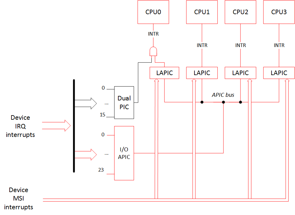
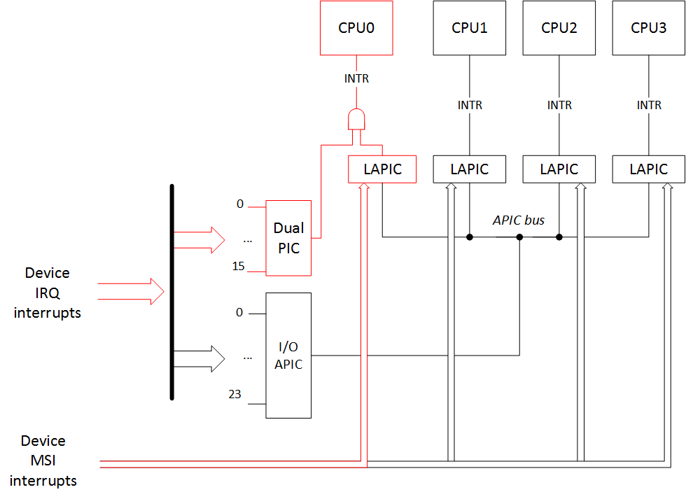
Everything here is like it is supposed to be in the modern system. For the devices and drivers which support MSI/MSI-X, this is the type of interrupt that they use. The rest of the interrupt routing is done through the APIC controller.
Simplistically, the interrupt routing schematics can be drawn like this: (red lines are active routing paths and black lines are unused routing paths)
A device that supports MSI/MSI-X interrupts should have that particular capability listed in its PCI configuration space.
As an example of that let's look at a little fragment of the lspci output for the devices that declare they use MSI/MSI-X. In our case it is a SATA controller (interrupt 'ahci'), two ethernet controllers (interrupts 'eth58*' and 'eth59*'), graphical controller ('i915'), and two HD Audio controllers ('snd_hda_intel').
lspci -v
00:02.0 VGA compatible controller: Intel Corporation Haswell-ULT Integrated Graphics Controller (rev 09) (prog-if 00 [VGA controller])
		...
		Capabilities: [90] MSI: Enable+ Count=1/1 Maskable- 64bit-
		Capabilities: [d0] Power Management version 2
		Capabilities: [a4] PCI Advanced Features
		Kernel driver in use: i915

00:03.0 Audio device: Intel Corporation Haswell-ULT HD Audio Controller (rev 09
		...
		Capabilities: [60] MSI: Enable+ Count=1/1 Maskable- 64bit-
		Capabilities: [70] Express Root Complex Integrated Endpoint, MSI 00
		Kernel driver in use: snd_hda_intel

00:1b.0 Audio device: Intel Corporation 8 Series HD Audio Controller (rev 04)
		...
		Capabilities: [60] MSI: Enable+ Count=1/1 Maskable- 64bit+
		Capabilities: [70] Express Root Complex Integrated Endpoint, MSI 00
		Capabilities: [100] Virtual Channel
		Kernel driver in use: snd_hda_intel


00:1f.2 SATA controller: Intel Corporation 8 Series SATA Controller 1 [AHCI mode] (rev 04) (prog-if 01 [AHCI 1.0])
		...
		Capabilities: [80] MSI: Enable+ Count=1/1 Maskable- 64bit-
		Capabilities: [70] Power Management version 3
		Capabilities: [a8] SATA HBA v1.0
		Kernel driver in use: ahci


05:00.0 Ethernet controller: Intel Corporation I350 Gigabit Network Connection (rev 01)
		...
		Capabilities: [50] MSI: Enable- Count=1/1 Maskable+ 64bit+
		Capabilities: [70] MSI-X: Enable+ Count=10 Masked-
		Capabilities: [a0] Express Endpoint, MSI 00
		Kernel driver in use: igb

05:00.1 Ethernet controller: Intel Corporation I350 Gigabit Network Connection (rev 01)
		...
		Capabilities: [50] MSI: Enable- Count=1/1 Maskable+ 64bit+
		Capabilities: [70] MSI-X: Enable+ Count=10 Masked-
		Capabilities: [a0] Express Endpoint, MSI 00
		Kernel driver in use: igb
As we see, all of these devices either have a string «MSI: Enable+» or «MSI-X: Enable+».
Let's downgrade our system! For a start let's boot with the kernel option 'pci=nomsi'.
pci=nomsi
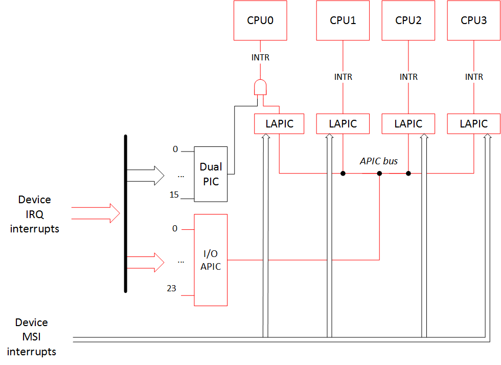
Because of this option MSI interrupts become IO-APIC/XT-PIC depending on the interrupt controller in use.
In this case the priority choice is still modern APIC controller, so the interrupt picture will be:
Output of /proc/interrupts:
           CPU0       CPU1       CPU2       CPU3
  0:         15          0          0          0   IO-APIC-edge      timer
  1:          0          1          0          1   IO-APIC-edge      i8042
  8:          0          0          1          0   IO-APIC-edge      rtc0
  9:          0          0          0          0   IO-APIC-fasteoi   acpi
 12:          0          0          0          1   IO-APIC-edge
 16:       1314       5625        342        555   IO-APIC-fasteoi   i915, snd_hda_intel, eth59
 17:          5          0          1         34   IO-APIC-fasteoi   eth58
 21:       2882       2558        963       2088   IO-APIC-fasteoi   ahci
 22:         26         81          2        170   IO-APIC-fasteoi   snd_hda_intel
 23:         23        369          8          8   IO-APIC-fasteoi   ehci_hcd:usb1
NMI:          0          0          0          0   Non-maskable interrupts
LOC:       3011       3331       2435       2617   Local timer interrupts
SPU:          0          0          0          0   Spurious interrupts
PMI:          0          0          0          0   Performance monitoring interrupts
IWI:        197        228        544         85   IRQ work interrupts
RTR:          3          0          0          0   APIC ICR read retries
RES:       1708       2349       1821       1569   Rescheduling interrupts
CAL:        520        554        509        555   Function call interrupts
TLB:        187        181        205        179   TLB shootdowns
TRM:        102        102        102        102   Thermal event interrupts
THR:          0          0          0          0   Threshold APIC interrupts
MCE:          0          0          0          0   Machine check exceptions
MCP:          2          2          2          2   Machine check polls
ERR:          0
MIS:          0
As expected, all MSI/MSI-X interrupts have disappeared. Instead of them devices now use interrupts of 'IO-APIC-fasteoi' type.
Let us draw our attention to the fact that earlier, before enabling this kernel boot option, each of the 'eth58' and 'eth59' had nine interrupts! But now each of them has only one interrupt. Recall that without the MSI, one function in the PCI device can have only one interrupt!
Here is a little info from the 'dmesg' command about the ethernet controllers' initialization:
— boot without the 'pci=nomsi' option:
igb: Intel(R) Gigabit Ethernet Network Driver - version 5.0.5-k
igb: Copyright (c) 2007-2013 Intel Corporation.
acpi:acpi_pci_irq_enable: igb 0000:05:00.0: PCI INT A -> GSI 16 (level, low) -> IRQ 16
igb 0000:05:00.0: irq 63 for MSI/MSI-X
igb 0000:05:00.0: irq 64 for MSI/MSI-X
igb 0000:05:00.0: irq 65 for MSI/MSI-X
igb 0000:05:00.0: irq 66 for MSI/MSI-X
igb 0000:05:00.0: irq 67 for MSI/MSI-X
igb 0000:05:00.0: irq 68 for MSI/MSI-X
igb 0000:05:00.0: irq 69 for MSI/MSI-X
igb 0000:05:00.0: irq 70 for MSI/MSI-X
igb 0000:05:00.0: irq 71 for MSI/MSI-X
igb 0000:05:00.0: added PHC on eth0
igb 0000:05:00.0: Intel(R) Gigabit Ethernet Network Connection
igb 0000:05:00.0: eth0: (PCIe:5.0Gb/s:Width x1) 00:15:d5:03:00:2a
igb 0000:05:00.0: eth0: PBA No: 106300-000
igb 0000:05:00.0: Using MSI-X interrupts. 4 rx queue(s), 4 tx queue(s)
acpi:acpi_pci_irq_enable: igb 0000:05:00.1: PCI INT B -> GSI 17 (level, low) -> IRQ 17
igb 0000:05:00.1: irq 72 for MSI/MSI-X
igb 0000:05:00.1: irq 73 for MSI/MSI-X
igb 0000:05:00.1: irq 74 for MSI/MSI-X
igb 0000:05:00.1: irq 75 for MSI/MSI-X
igb 0000:05:00.1: irq 76 for MSI/MSI-X
igb 0000:05:00.1: irq 77 for MSI/MSI-X
igb 0000:05:00.1: irq 78 for MSI/MSI-X
igb 0000:05:00.1: irq 79 for MSI/MSI-X
igb 0000:05:00.1: irq 80 for MSI/MSI-X
igb 0000:05:00.1: added PHC on eth1
igb 0000:05:00.1: Intel(R) Gigabit Ethernet Network Connection
igb 0000:05:00.1: eth1: (PCIe:5.0Gb/s:Width x1) 00:15:d5:03:00:2b
igb 0000:05:00.1: eth1: PBA No: 106300-000
igb 0000:05:00.1: Using MSI-X interrupts. 4 rx queue(s), 4 tx queue(s)
— boot with the 'pci=nomsi' option:
igb: Intel(R) Gigabit Ethernet Network Driver - version 5.0.5-k
igb: Copyright (c) 2007-2013 Intel Corporation.
acpi:acpi_pci_irq_enable: igb 0000:05:00.0: PCI INT A -> GSI 16 (level, low) -> IRQ 16
igb 0000:05:00.0: added PHC on eth0
igb 0000:05:00.0: Intel(R) Gigabit Ethernet Network Connection
igb 0000:05:00.0: eth0: (PCIe:5.0Gb/s:Width x1) 00:15:d5:03:00:2a
igb 0000:05:00.0: eth0: PBA No: 106300-000
igb 0000:05:00.0: Using legacy interrupts. 1 rx queue(s), 1 tx queue(s)
acpi:acpi_pci_irq_enable: igb 0000:05:00.1: PCI INT B -> GSI 17 (level, low) -> IRQ 17
igb 0000:05:00.1: added PHC on eth1
igb 0000:05:00.1: Intel(R) Gigabit Ethernet Network Connection
igb 0000:05:00.1: eth1: (PCIe:5.0Gb/s:Width x1) 00:15:d5:03:00:2b
igb 0000:05:00.1: eth1: PBA No: 106300-000
igb 0000:05:00.1: Using legacy interrupts. 1 rx queue(s), 1 tx queue(s)
Because of the decreased number of interrupts per device, enabling this option can lead to a significant performance limitation of the device driver, and that is not even counting that according to the Intel research 'Reducing Interrupt Latency Through the Use of Message Signaled Interrupts', MSI interrupts 3 times faster than the IO-APIC interrupts and 5 times faster than the PIC interrupts.
noapic
This option disables I/O APIC. MSI interrupts can still find their way to all of the CPUs, but the rest of interrupts from the devices can go only to CPU0, because PIC is only connected to CPU0. However, LAPIC is working and all other CPUs can still work and handle interrupts.

          CPU0      CPU1      CPU2      CPU3
  0:         5         0         0         0   XT-PIC-XT-PIC    timer
  1:         2         0         0         0   XT-PIC-XT-PIC    i8042
  2:         0         0         0         0   XT-PIC-XT-PIC    cascade
  8:         1         0         0         0   XT-PIC-XT-PIC    rtc0
  9:         0         0         0         0   XT-PIC-XT-PIC    acpi
 12:       172         0         0         0   XT-PIC-XT-PIC    ehci_hcd:usb1
 56:         0         0         0         0  PCI-MSI-edge      aerdrv, PCIe PME
 57:         0         0         0         0  PCI-MSI-edge      aerdrv, PCIe PME
 58:         0         0         0         0  PCI-MSI-edge      aerdrv, PCIe PME
 59:         0         0         0         0  PCI-MSI-edge      aerdrv, PCIe PME
 60:         0         0         0         0  PCI-MSI-edge      aerdrv, PCIe PME
 61:         0         0         0         0  PCI-MSI-edge      aerdrv, PCIe PME
 62:      2833      2989      1021       811  PCI-MSI-edge      ahci
 63:         0         1         0         0  PCI-MSI-edge      eth59
 64:       301        52         9         3  PCI-MSI-edge      eth59-rx-0
 65:        12        24         3       178  PCI-MSI-edge      eth59-rx-1
 66:        14        85         6         2  PCI-MSI-edge      eth59-rx-2
 67:        17        24       307         1  PCI-MSI-edge      eth59-rx-3
 68:        70        18         8        10  PCI-MSI-edge      eth59-tx-0
 69:         7         0         0        23  PCI-MSI-edge      eth59-tx-1
 70:        15       227         2         2  PCI-MSI-edge      eth59-tx-2
 71:        18         6        27         2  PCI-MSI-edge      eth59-tx-3
 72:         0         0         0         0  PCI-MSI-edge      eth58
 73:         1         0         0        27  PCI-MSI-edge      eth58-rx-0
 74:         1        22         0         5  PCI-MSI-edge      eth58-rx-1
 75:         1         0        22         5  PCI-MSI-edge      eth58-rx-2
 76:        23         0         0         5  PCI-MSI-edge      eth58-rx-3
 77:         1         0         0        27  PCI-MSI-edge      eth58-tx-0
 78:         1        22         0         5  PCI-MSI-edge      eth58-tx-1
 79:         1         0        22         5  PCI-MSI-edge      eth58-tx-2
 80:        23         0         0         5  PCI-MSI-edge      eth58-tx-3
 81:       187        17        70         7  PCI-MSI-edge      snd_hda_intel
 82:       698      1647       247       129  PCI-MSI-edge      i915
 83:       438       135        16        59  PCI-MSI-edge      snd_hda_intel
NMI:         0         0         0         0  Non-maskable interrupts
LOC:      1975      2499      2245      1474  Local timer interrupts
SPU:         0         0         0         0  Spurious interrupts
PMI:         0         0         0         0  Performance monitoring interrupts
IWI:       132        67       429        91  IRQ work interrupts
RTR:         3         0         0         0  APIC ICR read retries
RES:      1697      2178      1903      1541  Rescheduling interrupts
CAL:       561       496       534       567  Function call interrupts
TLB:       229       254       170       137  TLB shootdowns
TRM:        78        78        78        78  Thermal event interrupts
THR:         0         0         0         0  Threshold APIC interrupts
MCE:         0         0         0         0  Machine check exceptions
MCP:         2         2         2         2  Machine check polls
ERR:         0
MIS:         0
As we see, all IO-APIC-* interrupts have turned into XT-PIC-XT-PIC, and all of these interrupts have been routed to CPU0 only. MSI interrupts on the other hand have remained unchanged and go to all of the CPUs.
nolapic
This kernel boot option disables LAPIC. MSI interrupts can't work without LAPIC, and I/O APIC can't work without LAPIC either. All of the device interrupts can only go to the PIC, and it works with the CPU0 only. And without LAPIC the rest of the CPUs besides CPU0 won't work.

Output of /proc/interrupts:
            CPU0
  0:       6416    XT-PIC-XT-PIC    timer
  1:          2    XT-PIC-XT-PIC    i8042
  2:          0    XT-PIC-XT-PIC    cascade
  3:       5067    XT-PIC-XT-PIC    aerdrv, aerdrv, PCIe PME, PCIe PME, i915, snd_hda_intel, eth59
  4:         32    XT-PIC-XT-PIC    aerdrv, aerdrv, PCIe PME, PCIe PME, eth58
  5:          0    XT-PIC-XT-PIC    aerdrv, PCIe PME
  6:          0    XT-PIC-XT-PIC    aerdrv, PCIe PME
  8:          1    XT-PIC-XT-PIC    rtc0
  9:          0    XT-PIC-XT-PIC    acpi
 11:        274    XT-PIC-XT-PIC    snd_hda_intel
 12:        202    XT-PIC-XT-PIC    ehci_hcd:usb1
 15:       7903    XT-PIC-XT-PIC    ahci
NMI:          0   Non-maskable interrupts
LOC:          0   Local timer interrupts
SPU:          0   Spurious interrupts
PMI:          0   Performance monitoring interrupts
IWI:          0   IRQ work interrupts
RTR:          0   APIC ICR read retries
RES:          0   Rescheduling interrupts
CAL:          0   Function call interrupts
TLB:          0   TLB shootdowns
TRM:          0   Thermal event interrupts
THR:          0   Threshold APIC interrupts
MCE:          0   Machine check exceptions
MCP:          1   Machine check polls
ERR:          0
MIS:          0
Combinations of options:
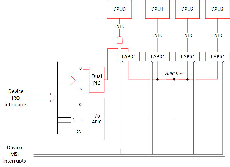
Actually there is only one combination for the new variant of routing: «noapic pci=nomsi». In this case all interrupts from the devices only go to the CPU0 through the PIC controller. But the LAPIC system is still working, so all the other CPUs can work and handle interrupts.
You cannot combine any other options with «nolapic» since it makes I/O APIC and MSI unaccessible. Therefore, if you've ever added Linux kernel boot options like «noapic nolapic» (or the most common case «acpi=off noapic nolapic») it seems like you've written some extra letters.
Finally, here is the result of the options «noapic pci=nomsi» to our interrupt routing picture:
And the output of /proc/interrupts is:
          CPU0       CPU1       CPU2       CPU3
  0:        5          0          0          0    XT-PIC-XT-PIC    timer
  1:        2          0          0          0    XT-PIC-XT-PIC    i8042
  2:        0          0          0          0    XT-PIC-XT-PIC    cascade
  3:     5072          0          0          0    XT-PIC-XT-PIC    i915, snd_hda_intel, eth59
  4:       32          0          0          0    XT-PIC-XT-PIC    eth58
  8:        1          0          0          0    XT-PIC-XT-PIC    rtc0
  9:        0          0          0          0    XT-PIC-XT-PIC    acpi
 11:      281          0          0          0    XT-PIC-XT-PIC    snd_hda_intel
 12:      200          0          0          0    XT-PIC-XT-PIC    ehci_hcd:usb1
 15:     7930          0          0          0    XT-PIC-XT-PIC    ahci
NMI:        0          0          0          0   Non-maskable interrupts
LOC:     2595       2387       2129       1697   Local timer interrupts
SPU:        0          0          0          0   Spurious interrupts
PMI:        0          0          0          0   Performance monitoring interrupts
IWI:      159         90        482        135   IRQ work interrupts
RTR:        3          0          0          0   APIC ICR read retries
RES:     1568       1666       1810       1833   Rescheduling interrupts
CAL:      431        556        549        558   Function call interrupts
TLB:      124        184        156        274   TLB shootdowns
TRM:      116        116        116        116   Thermal event interrupts
THR:        0          0          0          0   Threshold APIC interrupts
MCE:        0          0          0          0   Machine check exceptions
MCP:        2          2          2          2   Machine check polls
ERR:        0
MIS:        0
Interrupt routing tables and the options «acpi=noirq», «pci=noacpi», «acpi=off»
How does the operating system get information about the device interrupt routing? The BIOS prepares such info for the OS in the form of:
- ACPI tables (_PIC/_PRT functions)
- _MP_ table (MPtable)
- $PIR table
- Registers 0x3C/0x3D of the device's PCI configuration space
It is worth to note for the MSI interrupts declaration that the BIOS doesn't need to do anything extra (beside declaring the use of the LAPIC): all the aforementioned routing information is needed only for the APIC/PIC interrupt lines.
Tables in the list above are presented in the order of priority. Let's examine it in detail.
Let's assume the BIOS has presented all this data and we boot our OS without any extra boot options:
- OS finds ACPI tables.
- ОS executes ACPI function "_PIC", passing it the argument stating that the boot should happen in APIC mode. Here there is function code that usually saves the chosen mode in a variable (for example, PICM=1).
- To access interrupt routing info the OS calls ACPI function "_PRT". This checks the PICM variable and returns routing for the APIC mode case.
In the case when we boot with the option noapic:
- OS finds ACPI tables
- ОS executes ACPI function "_PIC", passing it the argument stating that the boot should happen in PIC mode. Here there is function code that usually saves the chosen mode in a variable (for example, PICM=0)
- To access interrupt routing info the OS calls ACPI function "_PRT". This checks the PICM variable and returns routing for the PIC mode case.
If ACPI tables aren't present or interrupt routing with ACPI is disabled through the option acpi=noirq or pci=noacpi (or ACPI subsystem is completely disabled with the acpi=off option), then the OS looks for the MPtable (_MP_) to get all the interrupt routing information:
- OS can't find/doesn't look at the ACPI tables
- OS finds MPtable (_MP_)
If ACPI tables aren't present or interrupt routing with ACPI is disabled through the option acpi=noirq or pci=noacpi (or ACPI subsystem is completely disabled with the acpi=off option), and if the MPtable (_MP_) is not present either (or there is a boot option noapic or nolapic):
- OS can't find/doesn't look at the ACPI tables
- OS can't find/doesn't look at the MPtable (_MP_)
- OS finds $PIR table
If there is no $PIR table or it is not full, then the OS will look at the registers 0x3C/0x3D of the device's PCI configuration space to guess interrupt routing.
Here is a picture summarizing all of this:

One should remember that not every BIOS provides all of these three tables (ACPI/MPtable/$PIR), so if you've passed an option to your bootloader (e.g. GRUB) that disables the use of ACPI or ACPI and MPtable for the interrupt routing, it is possible that your system won't boot.
Note 1: In the case when we try to boot in APIC mode with the option 'acpi=noirq' and without MPtable present, the picture of interrupts will be like in the case of normal booting with only the 'noapic' option. The operating system will go to PIC mode by itself. In the case when you try to boot without any ACPI tables at all ('acpi=off') and without MPtable present, then the picture will be like this:
           CPU0
  0:          6    XT-PIC-XT-PIC    timer
  1:          2    XT-PIC-XT-PIC    i8042
  2:          0    XT-PIC-XT-PIC    cascade
  8:          0    XT-PIC-XT-PIC    rtc0
 12:        373    XT-PIC-XT-PIC    ehci_hcd:usb1
 16:          0   PCI-MSI-edge      PCIe PME
 17:          0   PCI-MSI-edge      PCIe PME
 18:          0   PCI-MSI-edge      PCIe PME
 19:          0   PCI-MSI-edge      PCIe PME
 20:          0   PCI-MSI-edge      PCIe PME
 21:          0   PCI-MSI-edge      PCIe PME
 22:       8728   PCI-MSI-edge      ahci
 23:          1   PCI-MSI-edge      eth59
 24:       1301   PCI-MSI-edge      eth59-rx-0
 25:        113   PCI-MSI-edge      eth59-tx-0
 26:          0   PCI-MSI-edge      eth58
 27:         45   PCI-MSI-edge      eth58-rx-0
 28:         45   PCI-MSI-edge      eth58-tx-0
 29:       1280   PCI-MSI-edge      snd_hda_intel
NMI:          2   Non-maskable interrupts
LOC:      24076   Local timer interrupts
SPU:          0   Spurious interrupts
PMI:          2   Performance monitoring interrupts
IWI:       2856   IRQ work interrupts
RTR:          0   APIC ICR read retries
RES:          0   Rescheduling interrupts
CAL:          0   Function call interrupts
TLB:          0   TLB shootdowns
TRM:         34   Thermal event interrupts
THR:          0   Threshold APIC interrupts
MCE:          0   Machine check exceptions
MCP:          2   Machine check polls
ERR:          0
MIS:          0
This happens because without the ACPI MADT table (Multiple APIC Description Table) and the necessary info from the MPtable, the operating system doesn't know APIC identifiers (APIC IDs) for the other CPUs and can't work with them. But the LAPIC of the main CPU0 works because we haven't disabled it, and MSI interrupts can still go to it. So the interrupt picture would be:
Note 2: In general, interrupt routing with the use of ACPI in an APIC case should match the interrupt routing with the MPtable. Also, the interrupt routing with the use of ACPI in a PIC case should match the interrupt routing with the $PIR table. Therefore the '/proc/interrupts' output should not differ. But in my investigation I've noticed one strange fact. For some reason in the case of interrupt routing through the MPtable there is a cascade interrupt «XT-PIC-XT-PIC cascade» in the output:
           CPU0       CPU1       CPU2       CPU3
  0:         15          0          0          0   IO-APIC-edge      timer
  1:          2          0          0          0   IO-APIC-edge      i8042
  2:          0          0          0          0    XT-PIC-XT-PIC    cascade
  8:          0          1          0          0   IO-APIC-edge      rtc0
  9:          0          0          0          0   IO-APIC-edge      acpi
...
It is a little bit strange that it happens like that, but it seems like the kernel source documentation says that it is OK.
Сonclusion
In conclusion we review for one more time the discussed options.
Interrupt controller choice options:
- pci=nomsi — MSI interrupts become IO-APIC/XT-PIC depending on the interrupt controller in use.
- noapic — Disables I/O APIC. MSI interrupts can still go to all the other CPUs, the rest of the device interrupts can only go to the PIC, and it works with the CPU0 only. But LAPIC still works and other CPUs can work and handle interrupts.
- noapic pci=nomsi — All of the device interrupts can only go to the PIC, and it works with the CPU0 only. But LAPIC works and other CPUs can work and handle interrupts.
- nolapic — Disables LAPIC. MSI interrupts can't work without LAPIC, and I/O APIC can't work without LAPIC. All of the device interrupts can only go to the PIC, and it works with the CPU0 only. And without LAPIC the rest of the CPUs besides CPU0 won't work.
Interrupt tables priority options:
- no options — routing through the APIC with the help of ACPI tables
- noapic — routing through the PIC with the help of ACPI tables
- acpi=noirq (pci=noacpi/acpi=off) — routing through the APIC with the help of MPtable
- acpi=noirq (pci=noacpi/acpi=off) noapic (nolapic) — routing through the PIC with the help of $PIR
In the next part we will look at how coreboot configures the chipset for the interrupt routing.