[注]这个网站比较神奇的一点就在于,不解出来就不让你看答案。所以经常一个错误卡好久。。不过有大佬在GitHub发过答案了:
https://github.com/M-HHH/HDLBits_Practice_verilog
---------
31.Build a 2-to-1 mux that chooses between a and b. Choose b if both sel_b1 and sel_b2 are true. Otherwise, choose a. Do the same twice, once using assign statements and once using a procedural if statement.
// synthesis verilog_input_version verilog_2001
module top_module(
    input a,
    input b,
    input sel_b1,
    input sel_b2,
    output wire out_assign,
    output reg out_always   );
    assign out_assign = (sel_b1&sel_b2) ? b : a;
    always@(*)
        if (sel_b1&sel_b2)
            out_always=b;
        else
            out_always=a;
endmodule
32.The following code contains incorrect behaviour that creates a latch. Fix the bugs so that you will shut off the computer only if it's really overheated, and stop driving if you've arrived at your destination or you need to refuel.
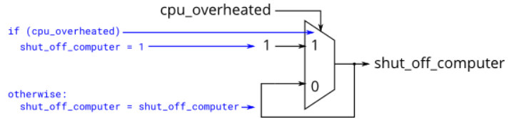
// synthesis verilog_input_version verilog_2001
module top_module (
    input      cpu_overheated,
    output reg shut_off_computer,
    input      arrived,
    input      gas_tank_empty,
    output reg keep_driving  ); //

    always @(*) begin
        shut_off_computer=cpu_overheated;
    end
    always @(*) begin
        keep_driving=(~arrived)&(~gas_tank_empty);
    end
endmodule


//-2/if语句条件不全的话会有latch;
// synthesis verilog_input_version verilog_2001
module top_module (
    input      cpu_overheated,
    output reg shut_off_computer,
    input      arrived,
    input      gas_tank_empty,
    output reg keep_driving  ); //

    always @(*) begin
        if (cpu_overheated)
            shut_off_computer = 1;
        else
            shut_off_computer = 0;
    end

    always @(*) begin
        if ((~arrived)&(~gas_tank_empty))
            keep_driving = 1;
        else
            keep_driving = 0;
    end
endmodule
33.Case statements are more convenient than if statements if there are a large number of cases. So, in this exercise, create a 6-to-1 multiplexer. When sel is between 0 and 5, choose the corresponding data input. Otherwise, output 0. The data inputs and outputs are all 4 bits wide. Be careful of inferring latches (See.always_if2)
// synthesis verilog_input_version verilog_2001
module top_module (
    input [2:0] sel,
    input [3:0] data0,
    input [3:0] data1,
    input [3:0] data2,
    input [3:0] data3,
    input [3:0] data4,
    input [3:0] data5,
    output reg [3:0] out   );//

    always@(*) begin  // This is a combinational circuit
        case(sel)
            3'b000: out<=data0;
            3'b001: out<=data1;
            3'b010: out<=data2;
            3'b011: out<=data3;
            3'b100: out<=data4;
            3'b101: out<=data5;
            3'b110: out<=4'b0000;
            3'b111: out<=4'b0000;
        endcase
    end
endmodule
34.A priority encoder is a combinational circuit that, when given an input bit vector, outputs the position of the first 1 bit in the vector. For example, a 8-bit priority encoder given the input 8'b10010000 would output 3'd4, because bit[4] is first bit that is high.
Build a 4-bit priority encoder. For this problem, if none of the input bits are high (i.e., input is zero), output zero. Note that a 4-bit number has 16 possible combinations.
// synthesis verilog_input_version verilog_2001
module top_module (
    input [3:0] in,
    output reg [1:0] pos  );
    always@(*) begin
        case(in)
            4'b0000:pos=2'b00;
            4'b0001:pos=2'b00;
            4'b0010:pos=2'b01;
            4'b0011:pos=2'b00;
            4'b0100:pos=2'b10;
            4'b0101:pos=2'b00;
            4'b0110:pos=2'b01;
            4'b0111:pos=2'b00;
            4'b1000:pos=2'b11;
            4'b1001:pos=2'b00;
            4'b1010:pos=2'b01;
            4'b1011:pos=2'b00;
            4'b1100:pos=2'b10;
            4'b1101:pos=2'b00;
            4'b1110:pos=2'b01;
            4'b1111:pos=2'b00;
        endcase
    end
endmodule

/*
always @(*) begin
    casez (in[3:0])
        4'bzzz1: out = 0;   // in[3:1] can be anything
        4'bzz1z: out = 1;
        4'bz1zz: out = 2;
        4'b1zzz: out = 3;
        default: out = 0;
    endcase
end
*/
35.Build a priority encoder for 8-bit inputs. Given an 8-bit vector, the output should report the first bit in the vector that is 1. Report zero if the input vector has no bits that are high. For example, the input 8'b10010000 should output 3'd4, because bit[4] is first bit that is high.
From the previous exercise (always_case2), there would be 256 cases in the case statement. We can reduce this (down to 9 cases) if the case items in the case statement supported don't-care bits. This is what casez is for: It treats bits that have the value z as don't-care in the comparison.
// synthesis verilog_input_version verilog_2001
module top_module (
    input [7:0] in,
    output reg [2:0] pos  );
    always @(*) begin
        casez(in)
            8'bzzzzzzz1: pos=0;
            8'bzzzzzz1z: pos=1;
            8'bzzzzz1zz: pos=2;
            8'bzzzz1zzz: pos=3;
            8'bzzz1zzzz: pos=4;
            8'bzz1zzzzz: pos=5;
            8'bz1zzzzzz: pos=6;
            8'b1zzzzzzz: pos=7;
            default: pos=0;
        endcase
    end
endmodule
36.Suppose you're building a circuit to process scancodes from a PS/2 keyboard for a game. Given the last two bytes of scancodes received, you need to indicate whether one of the arrow keys on the keyboard have been pressed. This involves a fairly simple mapping, which can be implemented as a case statement (or if-elseif) with four cases.
| Scancode [15:0] | Arrow key |
|---|---|
| 16'he06b | left arrow |
| 16'he072 | down arrow |
| 16'he074 | right arrow |
| 16'he075 | up arrow |
| Anything else | none |
// synthesis verilog_input_version verilog_2001
module top_module (
    input [15:0] scancode,
    output reg left,
    output reg down,
    output reg right,
    output reg up  );
    always @(*) begin
        up = 1'b0; down = 1'b0; left = 1'b0; right = 1'b0;
        case (scancode)
            16'he06b:left = 1'b1;
            16'he072:down = 1'b1;
            16'he074:right = 1'b1;
            16'he075:up = 1'b1;
            default: ;
        endcase
    end
endmodule
37.Given four unsigned numbers, find the minimum. Unsigned numbers can be compared with standard comparison operators (a < b). Use the conditional operator to make two-way min circuits, then compose a few of them to create a 4-way min circuit. You'll probably want some wire vectors for the intermediate results. Expected solution length: Around 5 lines.
module top_module (
    input [7:0] a, b, c, d,
    output [7:0] min);//
    wire [7:0] minab,mincd;
    assign minab=(a>b)?b:a;
    assign mincd=(c>d)?d:c;
    assign min=(minab>mincd)?mincd:minab;
    // assign intermediate_result1 = compare? true: false;
endmodule
38.Parity checking is often used as a simple method of detecting errors when transmitting data through an imperfect channel. Create a circuit that will compute a parity bit for a 8-bit byte (which will add a 9th bit to the byte). We will use "even" parity, where the parity bit is just the XOR of all 8 data bits.
module top_module (
    input [7:0] in,
    output parity);
    assign parity = ^ in[7:0];
endmodule
39.Build a combinational circuit with 100 inputs, in[99:0].
There are 3 outputs:
- out_and: output of a 100-input AND gate.
- out_or: output of a 100-input OR gate.
- out_xor: output of a 100-input XOR gate.
module top_module(
    input [99:0] in,
    output out_and,
    output out_or,
    output out_xor
);
    assign out_and = & in[99:0];
    assign out_or = | in[99:0];
    assign out_xor = ^ in[99:0];
endmodule
40.Given a 100-bit input vector [99:0], reverse its bit ordering.
module top_module(
    input [99:0] in,
    output [99:0] out
);
    always@(*)
        begin
            for (integer i=0;i<100;i=i+1)
                out[i]=in[99-i];
        end
endmodule
41.A "population count" circuit counts the number of '1's in an input vector. Build a population count circuit for a 255-bit input vector.
module top_module(
    input [254:0] in,
    output [7:0] out );
    always@(*)
        begin
            out=0;
            for (integer i=0;i<255;i=i+1)
                if (in[i])
                    out=out+1;
                else
                     ;
        end
endmodule
//Warning (10230): Verilog HDL assignment warning at top_module.v(9):
//truncated value with size 32 to match size of target (8)

//答案
module top_module (
    input [254:0] in,
    output reg [7:0] out
);

    always @(*) begin    // Combinational always block
        out = 0;
        for (int i=0;i<255;i++)
            out = out + in[i];
    end

endmodule
42.Create a 100-bit binary ripple-carry adder by instantiating 100 full adders. The adder adds two 100-bit numbers and a carry-in to produce a 100-bit sum and carry out. To encourage you to actually instantiate full adders, also output the carry-out from each full adder in the ripple-carry adder. cout[99] is the final carry-out from the last full adder, and is the carry-out you usually see.
module top_module(
    input [99:0] a, b,
    input cin,
    output [99:0] cout,
    output [99:0] sum );
    assign cout[0] = a[0] & b[0] | a[0] & cin | b[0] & cin;
    assign sum[0]  = a[0] ^ b[0] ^ cin;


    integer i;

    always @ (*) begin
        for (i=1; i<100; i++) begin
            cout[i] = a[i] & b[i] | a[i] & cout[i-1] | b[i] & cout[i-1];
            sum[i]  = a[i] ^ b[i] ^ cout[i-1];
        end
    end
endmodule
//There are many full adders to instantiate. An instance array or generate statement would help here.
//这应该不是题目要求的解法
43.You are provided with a BCD one-digit adder named bcd_fadd that adds two BCD digits and carry-in, and produces a sum and carry-out.
module bcd_fadd {
    input [3:0] a,
    input [3:0] b,
    input     cin,
    output   cout,
    output [3:0] sum );
Instantiate 100 copies of bcd_fadd to create a 100-digit BCD ripple-carry adder. Your adder should add two 100-digit BCD numbers (packed into 400-bit vectors) and a carry-in to produce a 100-digit sum and carry out.
module top_module(
    input [399:0] a, b,
    input cin,
    output cout,
    output [399:0] sum );
    wire [99:0] ccout;
    bcd_fadd inst1 (a[3:0],b[3:0],cin,ccout[0],sum[3:0]);
    genvar i;
    generate
        for (i=1;i<100;i++)
            begin : label
                bcd_fadd fadd (a[4*i+3:4*i],b[4*i+3:4*i],ccout[i-1],ccout[i],sum[4*i+3:4*i]);
            end
    endgenerate
    assign cout=ccout[99];
endmodule
//
//Warning (10230): Verilog HDL assignment warning at tb_modules.sv(8): truncated value with size 32 to match size
//of target (4) File: /var/www/verilog/work/vlgSZma3E_dir/tb_modules.sv Line: 8

//GITHUB的答案
module top_module(
    input [399:0] a, b,
    input cin,
    output cout,
    output [399:0] sum );

    wire [399:0] cout_tmp;
    bcd_fadd fadd(.a(a[3:0]), .b(b[3:0]), .cin(cin), .cout(cout_tmp[0]),.sum(sum[3:0]));
    assign cout = cout_tmp[396];

    generate
        genvar i;
        for(i = 4; i < 400; i=i+4) begin : adder
            bcd_fadd fadd(.a(a[i+3:i]), .b(b[i+3:i]), .cin(cout_tmp[i-4]), .cout(cout_tmp[i]),.sum(sum[i+3:i]));
        end
    endgenerate

endmodule