一、配置mykernel 2.0
本次实验使用的是Ubuntu 20.04 LTS 64位系统,运行在虚拟机中。
在项目主页(https://github.com/mengning/mykernel)上有详细的安装配置教程,主要命令如下:
 1 wget https://raw.github.com/mengning/mykernel/master/mykernel-2.0_for_linux-5.4.34.patch
 2 sudo apt install axel
 3 axel -n 20 https://mirrors.edge.kernel.org/pub/linux/kernel/v5.x/linux-5.4.34.tar.xz
 4 xz -d linux-5.4.34.tar.xz
 5 tar -xvf linux-5.4.34.tar
 6 cd linux-5.4.34
 7 patch -p1 < ../mykernel-2.0_for_linux-5.4.34.patch
 8 sudo apt install build-essential libncurses-dev bison flex libssl-dev libelf-dev
 9 make defconfig # Default configuration is based on 'x86_64_defconfig'11 make -j$(nproc) # 编译的时间比较久哦
12 sudo apt install qemu # install QEMU
13 qemu-system-x86_64 -kernel arch/x86/boot/bzImage
有几个地方需要注意:
- github和linux kernel下载较慢,甚至可能无法下载,可以直接使用别人已经下载好的文件。
- make -j后面是编译时的线程数,设置适当的线程数可以加快编译速度,一般以cpu核心数的1-2倍为宜,太多的话反而会降低编译速度。
- 在Ubuntu20.04系统中,仅安装qemu的话是默认没有安装各个系统架构的,需要额外手动安装。此时,可以使用sudo apt-get install qemu-system-x86来安装x86平台。
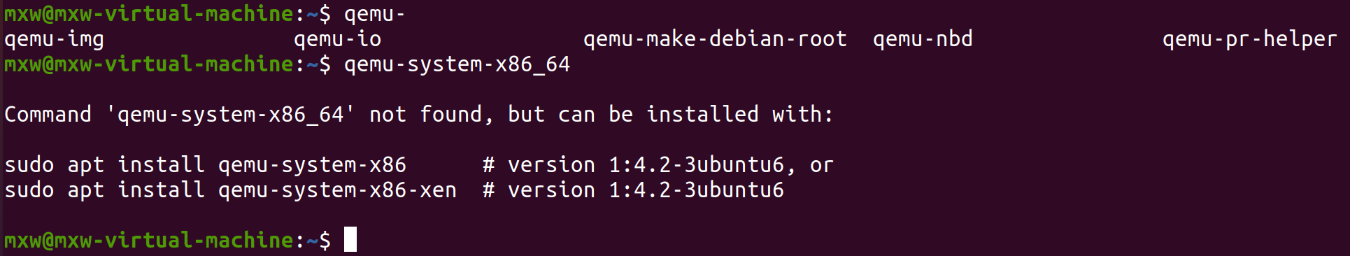
安装完成后,使用qemu-system-x86_64 -kernel arch/x86/boot/bzImage命令即可启动内核(注意内核镜像的路径)。

二、编写并分析操作系统内核核心功能
此次实验的操作系统内核,调度策略是基于时间片轮转的先入先出策略。
对于一个多任务操作系统,进程控制块(PCB,Process Control Block)是必不可少的,它保存了进程的管理和控制信息。PCB至少需要包含当前进程的id,进程运行状态,栈空间,cpu状态信息,进程入口等。对于实验的操作系统,其PCB使用链表方式存储,还应该增加一个指向下个PCB的指针。
以下mypcb.h文件中定义了PCB的结构,将其放在/linux-5.4.34/mykernel中。
 1 /* 定义支持的最大任务数 */
 2 #define MAX_TASK_NUM        4
 3 /* 定义任务堆栈的大小 */
 4 #define KERNEL_STACK_SIZE   1024
 5 /* 当前任务的rsp和rip寄存器 */
 6 struct Thread {
 7     unsigned long        ip;
 8     unsigned long        sp;
 9 };
10
11 typedef struct PCB{
12     int pid;
13     volatile long state;    /* -1 unrunnable, 0 runnable, >0 stopped */
14     unsigned long stack[KERNEL_STACK_SIZE];
15     struct Thread thread;
16     unsigned long    task_entry; /* 任务入口 */
17     struct PCB *next;
18 }tPCB;
19
20 void my_schedule(void);
定义完PCB结构后,就可以依此创建进程。创建进程和进程具体执行的代码在mymain.c中,其内容如下:
 1 #include <linux/types.h>
 2 #include <linux/string.h>
 3 #include <linux/ctype.h>
 4 #include <linux/tty.h>
 5 #include <linux/vmalloc.h>
 6
 7 #include "mypcb.h"
 8
 9 tPCB task[MAX_TASK_NUM];
10 tPCB * my_current_task = NULL;
11 volatile int my_need_sched = 0;
12
13 void my_process(void);
14
15
16 void __init my_start_kernel(void)
17 {
18     int pid = 0;
19     int i;
20     /* 初始化0号进程 */
21     task[pid].pid = pid;
22     task[pid].state = 0;/* -1 unrunnable, 0 runnable, >0 stopped */
23     task[pid].task_entry = task[pid].thread.ip = (unsigned long)my_process;
24     task[pid].thread.sp = (unsigned long)&task[pid].stack[KERNEL_STACK_SIZE-1];
25     task[pid].next = &task[pid];
26     /*fork more process */
27     for(i=1;i<MAX_TASK_NUM;i++)
28     {
29         memcpy(&task[i],&task[0],sizeof(tPCB));
30         task[i].pid = i;
31         task[i].thread.sp = (unsigned long)(&task[i].stack[KERNEL_STACK_SIZE-1]);
32         task[i].next = task[i-1].next; /* 当前进程的next指针指向task[0] */
33         task[i-1].next = &task[i];     /* 修改前个进程的next指针指向当前进程 */
34     }
35     /* start process 0 by task[0] */
36     pid = 0;
37     my_current_task = &task[pid];
38     asm volatile(
39         "movq %1,%%rsp
	"     /* 将PCB中的sp地址存入rsp中 */
40         "pushq %1
	"             /* push rbp */
41         "pushq %0
	"             /* push task[pid].thread.ip */
42         "ret
	"                 /* 两行代码将PCB中的ip地址存入rip中 */
43         :
44         : "c" (task[pid].thread.ip),"d" (task[pid].thread.sp)
45     );
46 }
47
48 void my_process(void)
49 {
50     int i = 0;
51     while(1)
52     {
53         i++;
54         if(i%90000000 == 0)
55         {
56             printk(KERN_NOTICE "this is process %d -
",my_current_task->pid);
57             if(my_need_sched == 1)
58             {
59                 my_need_sched = 0;
60                 my_schedule(); /* 进程调度 */
61             }
62             printk(KERN_NOTICE "this is process %d +
",my_current_task->pid);
63         }
64     }
65 }
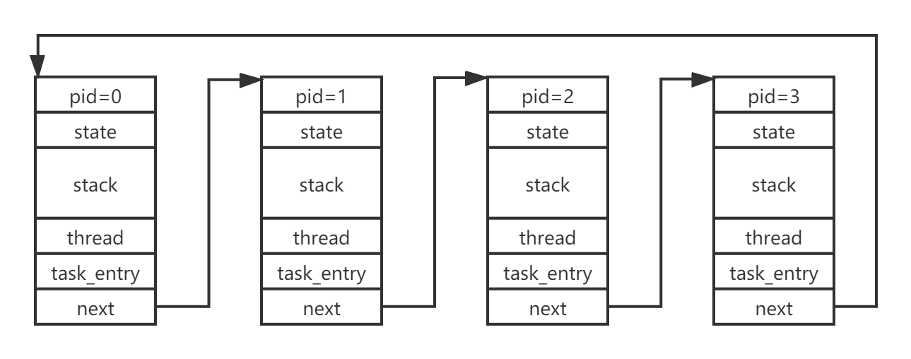
当内核启动后,会进入到my_start_kernel函数中,我们首先初始化0号进程,并依次fork出其余的进程。从27行到34行的循环代码运行结束后,定义的4个进程就初始化完成了,此时内存中PCB的存储结构如下图所示:
各个进程创建完成后,开始启动0号进程,第39到42行的汇编代码就是用于启动0号进程的。由于此时0号进程还未启动运行,它的栈是空栈,其栈顶和栈底是同样的值,所以40行代码的作用是将rbp压入栈中。另外,由于没有办法直接修改rip指针,所以第41行代码先将PCB中的ip压入堆栈,再通过42行的ret指令将其存入到rip寄存器中。接着就会执行my_process函数。
进程创建完成后,需要完成内容的自然是进程调度了。本系统的调度是基于时间片的,那么在定时器中断函数中,当运行了指定的事件后,需要对调度的标志位进行置为,告诉进程其时间片已经用完,需要放弃cpu给其他进程使用。定时器的中断处理函数如下:
 1 void my_timer_handler(void)
 2 {
 3     /* 时间片用完,需要进行调度 */
 4     if(time_count%1000 == 0 && my_need_sched != 1)
 5     {
 6         printk(KERN_NOTICE ">>>It's time to schedule...<<<
");
 7         my_need_sched = 1;
 8     }
 9     time_count ++ ;
10     return;
11 }
当进程发现my_need_sched被置为1后,就会调用my_schedule函数进行进程切换,其内容如下:
 1 void my_schedule(void)
 2 {
 3     tPCB * next;
 4     tPCB * prev;
 5
 6     if( (my_current_task == NULL) || (my_current_task->next == NULL) )
 7         return;
 8
 9     printk(KERN_NOTICE ">>>schedule start...<<<
");
10     /* schedule */
11     next = my_current_task->next;
12     prev = my_current_task;
13     if(next->state == 0)/* -1 unrunnable, 0 runnable, >0 stopped */
14     {
15         my_current_task = next;
16         printk(KERN_NOTICE ">>>switch %d to %d<<<
",prev->pid,next->pid);
17         /* switch to next process */
18         asm volatile(
19             "pushq %%rbp
	"         /* 保存当前进程的rbp */
20             "movq %%rsp,%0
	"     /* 保存当前进程的rsp到PCB中 */
21             "movq %2,%%rsp
	"     /* rsp切换到下一个进程的栈 */
22             "movq $1f,%1
	"       /* 保存当前进程的rip到PCB中 */
23             "pushq %3
	"
24             "ret
	"                 /* restore  rip of next */
25             "1:	"                  /* next process start here */
26             "popq %%rbp
	"
27             : "=m" (prev->thread.sp),"=m" (prev->thread.ip)
28             : "m" (next->thread.sp),"m" (next->thread.ip)
29         );
30     }
31     return;
32 }
进程切换主要完成的工作是进程堆栈的切换和指令指针rip的切换。其中,19到21行这三行代码,保存了当前进程的rbp和rsp,然后将当前的栈指针指向了下一个进程的栈的栈顶,完成了两个进程的堆栈的切换。接着,22到24行的代码完成了rip寄存器的更改,和前面讲的操作类似,也是通过push和ret指令来间接地完成了rip寄存器的修改。最后,通过26行的pop指令完成rbp寄存器的恢复。至此,进程的切换就完成了。
重新编译后运行,发现可以进行进程切换。
