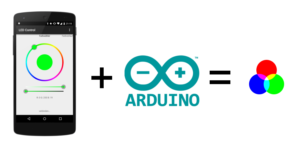
About this project
This project was developed after I had to find out that controlling my RGB ambient light with the normal infrared remote control was complicated and not reliable. Within a few months I build this solution that enabled controlling my LEDs with a Bluetooth-enabled Android Device running a self programmed app. On the hardware side an Arduino is receiving the commands and controlling three PWM signals.
The app is available at Google Play for free (but closed source), the Arduino sketch is released under Apache License. The used protocol is also documented in this wiki and open for usage by others.
If you like this project I would be pleased with recommendations or a good rating at Google Play. Let me also know when you find some bugs.
Requirements
You need a few things to get started:
- Arduino Uno
- Android powered Phone/Tablet with bluetooth running Android 4.0 or above
- RGB-LED-Stripes with common anode (one common '+' and a seperate '-/GND' for each color) (you can also use stripes with common cathodes, but the showed circuit diagramm will not work (in particular the output stage). A solution therefore is also available.)
- External Power Supply (to power Arduino and LEDs)
- USART capable bluetooth module (for example HC-06, available on ebay for < 10$)
- 3x 220 Ohm resistors (gate current limiter)
- 3x 10 kOhm resistors (gate pull-down)
- 3x N-Channel Power-MOSFETs (enhancement mode) (for example IRF1404)
optional voltage divider
- 1x 4,7 kOhm resistor
- 1x 10 kOhm resistor
Assembly
Connect the Arduino and the others parts as showed below. Be sure that you do not change the RX pin with the TX pin of the bluetooth module. In General: RX of the bluetooth module has to be connected to TX of Arduino and vice versa.
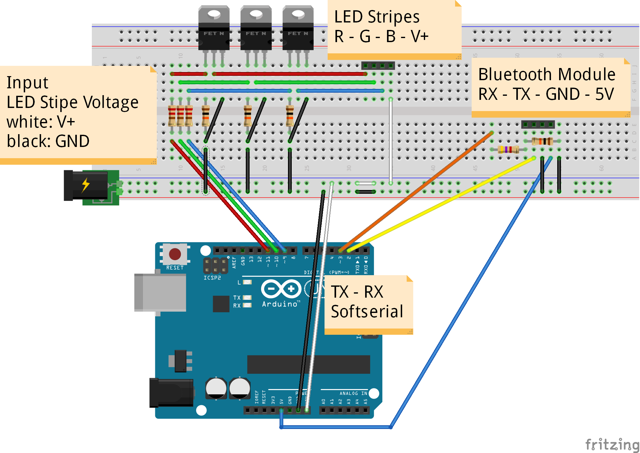
Caution: The HC-06 bluetooth module I bought works with 3,3V. You can power it with 5V because there is a built-in voltage regulator (make sure that yours has also one or power it with 3,3V), but RX and TX are not 5V tolerant. To avoid permanent damage the Arduino output-voltage is reduced to 3,3V by a voltage divider (therefore the 4k7 and 10k resistors). On the other hand a special step-up circuit is not necessary because the Arduino recognizes 3,3V of the bluetooth module as HIGH-Level.
Note: For permanent installations you should consider soldering your circuit on a Arduino Proto Shield (bought or home made). I personally soldered everything on a stripboard and put the whole thing in a small case.
Note: You don't need the connection from TX (pin 3) on Arduino to RX of the bluetooth module, because currently nothing will be send back to the Android device. Just remove the connection from pin 3 (Arduino) to RX (bluetooth module) and the voltage divider. It may be possible that a bidirectional communication will be used in future releases.
Installing the software
You're almost done. Now you need to install the software and select the target device.
- Upload the Arduino Sketch (https://github.com/fennel-labs/LED-control/blob/master/LEDControlArduino.ino)
- Install the Android app on your phone (https://play.google.com/store/apps/details?id=com.fennel.ledcontrol)
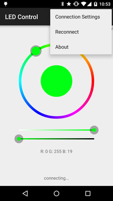
- Start a new bluetooth device discovery (Android -> Settings -> Bluetooth -> Add)
- Start the LED Control app and select your receiver (LED Control -> Connection Settings -> your device)
Troubleshooting
There are several reasons why your circuit may not work as intended. Here are some possibilities:
- Check if the LED voltage is high enough and your stripes have the right polarity by connecting them directly to your power source.
- Are RX and TX connected in the right way? Read also the notes above.
- By default, the Arduino sends some debug data to the PC via the hardware serial. If the Software in Arduino behaves abnormal check the console log.
- In case you are not sure whether your bluetooth module works properly or not, connect it directly to your Arduino (still keeping the voltage levels in mind, see note above). Therefore you have to remove the 328P chip temporary from your Uno.
- To check the output stage, you can try pulling the gate of each channel to ground or +5V.
thanks:https://github.com/fennel-labs