来源:https://developer.arm.com/architectures/learn-the-architecture/aarch64-virtualization/single-page
Introduction to virtualization
Here we will introduce some introductory hypervisor and virtualization theory. If you are already familiar with these concepts, you might want to skip this material.
We use the term hypervisor in this guide to mean a piece of software that is responsible for creating, managing, and scheduling of Virtual Machines (VMs).
Why is virtualization important?
Virtualization is a widely used technology, and underpins almost all modern cloud computing and enterprise infrastructure. Virtualization is used by developers to run multiple Operating Systems (OS) on a single machine, and to test software without the risk of damaging the main computing environment.
Virtualization is popular for server systems, and support for virtualization is a requirement for most server grade processors. This is because virtualization gives very desirable features to the data center, including:
- Isolation: At its core, virtualization provides isolation between virtual machines running on a single physical system. This isolation allows the sharing of a physical system between mutually distrusting computing environments. For example, two competitors can share the same physical machine in a data center without being able to access each other’s data.
- High Availability: Virtualization allows
seamless and transparent migration of workloads between physical
machines. This technique is commonly used to migrate workloads away from
a faulting hardware platform that may require maintenance and
replacement.
- Workload balancing: To optimize the hardware
and power budget of the data center, it is important to use each
hardware platform as much as possible. Again, this can be achieved using
migration of virtual machines, or by co-hosting suitable workloads on
physical machines. This means that the physical machines are used for as
much of their capacity as possible. This provides the best power budget
for the data center provider, and the best performance for the tenant.
- Sandboxing: VMs can be used to provide sandboxes for applications that might interfere with the rest of the machine that they run on. Examples of such applications include legacy applications, or software that is in development. Running those applications in a VM prevents bugs or malicious parts of the applications from interfering with other applications or data on the physical machine.
Standalone and hosted hypervisors
Hypervisors can be divided into two broad categories: standalone, or Type 1, hypervisors and hosted, or Type 2, hypervisors.
We will look first at a hosted, or Type 2, hypervisor. In a Type 2 hypervisor configuration, the Host OS has full control of the hardware platform and all its resources, including CPU and physical memory. The following diagram illustrates a hosted, or Type 2, hypervisor:

If you have previously used software such as Virtual Box or VMware Workstation, this is the type of hypervisor that you were running. An OS, referred to as the Host OS, is installed on the platform and the hypervisor runs within the Host OS, taking advantage of existing functionality to manage hardware. The hypervisor can then host virtual machines, which themselves run an OS. We refer to this as the Guest OS.
Next, we will look first at a standalone, or Type 1, hypervisor:

You can see that there is no Host OS in this hypervisor design. The hypervisor runs directly on the hardware, and has full control of the hardware platform and all its resources, including CPU and physical memory. Just like hosted hypervisors, standalone hypervisors can host virtual machines. These virtual machines can run one, or more than one, full Guest OS.
The two most commonly used open-source hypervisors on Arm platforms are Xen (standalone, Type 1) and KVM (hosted, Type 2). We will use these hypervisors to illustrate some of the points in this guide. However, there are many other hypervisors available, both open source and proprietary.
Full virtualization and para-virtualization
The classic definition of a VM is a separate, isolated computing environment, which is indistinguishable from the real physical machine. Even though it is possible to fully emulate real machines on Arm-based system, this is often not an efficient thing to do. Therefore, this kind of emulation is not done very often. For example, emulating a real Ethernet device is slow, because each access to an emulated register performed by the Guest OS must be handled in software by the hypervisor. This handling can be much more expensive than accessing registers on a physical device.
A preferred alternative, which is usually used to improve performance, is to enlighten the Guest OS. By making the Guest OS aware that it is running in a VM, and by providing virtual devices that are designed to have good performance when being emulated in the hypervisor and accessed from a Guest OS, a Guest OS can achieve good performance, even for I/O.
Strictly speaking, full system virtualization emulates a real
physical machine. Xen (the open source project), on the other hand,
popularized the term paravirtualization, in which core parts of the
Guest OS are modified to operate on a virtual hardware platform instead
of a physical machine. This modification is undertaken to improve
performance.
Today, on most architectures that have hardware support for
virtualization, including Arm, the Guest OS runs mostly unmodified. The
Guest OS thinks that it is operating on real hardware, except for
drivers for I/O peripherals such as block storage and networking, which
use paravirtualized devices and device drivers. Examples of such
paravirtualized I/O devices are Virtio and Xen PV Bus.
Virtual machines and virtual CPUs
It is important to understand the difference between a Virtual Machine (VM) and a Virtual CPU (vCPU). A VM will contain one or more vCPUs, as shown in the following diagram:
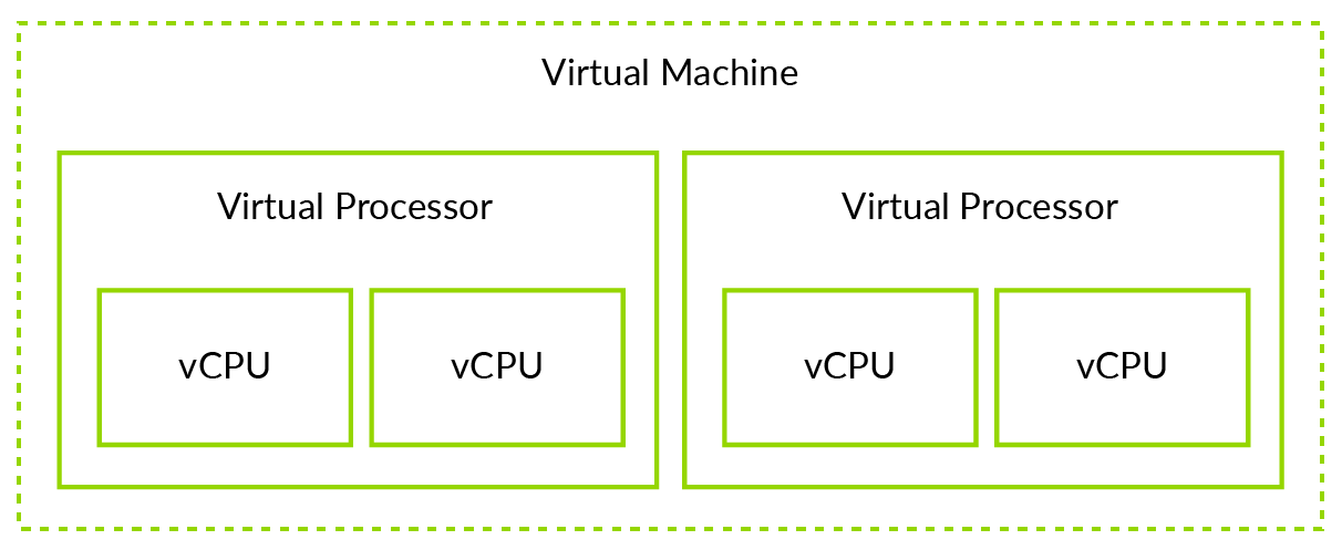
The distinction between VM and vCPU will become important when we look at some of the other topics in this guide. For example, a page of memory might be allocated to a VM, and therefore be accessible to all the vCPUs in that VM. However, a virtual interrupt is targeted at a specific vCPU, and can only go to that vCPU.
Note: Strictly, we should refer to a virtual Processing Element (vPE), rather than a vCPU. Remember that a Processing Element (PE) is the generic term for a machine that implements the Arm architecture. This guide uses vCPU instead of vPE, because vCPU is the term that most people are familiar with. However, in the architecture specifications, the term vPE is used.
Virtualization in AArch64
Software running at EL2 or higher has access to several controls for virtualization:
- Stage 2 translation
- EL1/0 instruction and register access trapping
- Virtual exception generation
The Exception Levels (ELs) in Non-Secure and Secure states are shown here:

In the diagram, Secure EL2 is shown in grey. This is because support for EL2 in Secure state is not always available. This is discussed in the section on Secure virtualization.
- Secure virtualization
- Hosted, or Type 2, hypervisors
- Nested virtualization
Stage 2 translation
What is stage 2 translation?
Stage 2 translation allows a hypervisor to control a view of memory in a Virtual Machine (VM). Specifically, it allows the hypervisor to control which memory-mapped system resources a VM can access, and where those resources appear in the address space of the VM.
This ability to control memory access is important for isolation and sandboxing. Stage 2 translation can be used to ensure that a VM can only see the resources that are allocated to it, and not the resources that are allocated to other VMs or the hypervisor.
For memory address translation, stage 2 translation is a second stage of translation. To support this, a new set of translation tables known as Stage 2 tables, are required, as shown here:
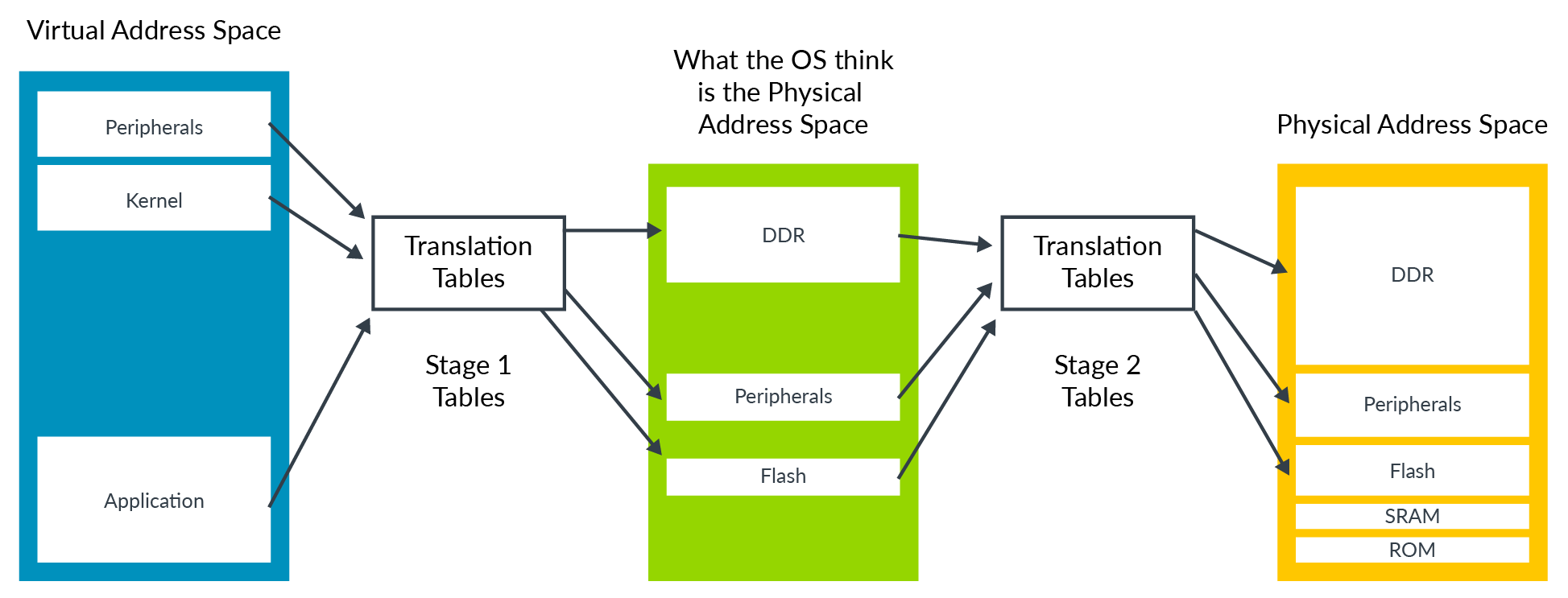
An Operating System (OS) controls a set of translation tables that map from the virtual address space to what it thinks is the physical address space. However, this process undergoes a second translation into the real physical address space. This second stage is controlled by the hypervisor.
The OS-controlled translation is called stage 1 translation, and the hypervisor-controlled translation is called stage 2 translation. The address space that the OS thinks is physical memory is referred to as the Intermediate Physical Address (IPA) space.
Note: For an introduction to how address translation works, see our guide on Memory Management.
The format of the translation tables used for stage 2 is very similar
to that used for stage 1. However, some of the attributes are handled
differently in stage 2 and the Type, Normal or Device, is encoded
directly into table entry rather than via a MAIR_ELx register.
VMIDs
Each VM is assigned a virtual machine identifier (VMID). The VMID is used to tag translation lookaside buffer (TLB) entries, to identify which VM each entry belongs to. This tagging allows translations for multiple different VMs to be present in the TLBs at the same time.
The VMID is stored in VTTBR_EL2 can either be 8 or 16 bits. The VMID is controlled by the VTCR_EL2.VS bit. Support for 16-bit VMIDs is optional, and was added in Armv8.1-A.
Note: Translations for the EL2 and EL3 translation regimes are not tagged with a VMID, because they are not subject to stage 2 translation.
VMID interaction with ASIDs
TLB entries can also be tagged with an Address Space Identifier (ASID). An application is assigned an ASID by the OS, and all the TLB entries in that application are tagged with that ASID. This means that TLB entries for different applications are able to coexist in the TLB, without the possibility that one application uses the TLB entries that belong to a different application.
Each VM has its own ASID namespace. For example, two VMs might both use ASID 5, but they use them for different things. The combination of ASID and VMID is the thing that is important.
Attribute combining and overriding
The stage 1 and stage 2 mappings both include attributes, such as type and access permissions. The Memory Management Unit (MMU) combines the attributes from the two stages to give a final effective value. The MMU does this by selecting the stage that is more restrictive, as you can see here:
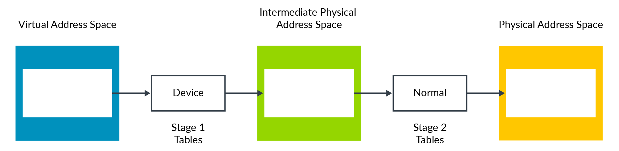
In this example, the Device type is more restrictive than the Normal type. Therefore, the resulting type is Device. The result would be the same if we reversed the example, so that stage 1 = Normal, and stage 2 = Device.
This method of combining attributes works for most use cases, but sometimes the hypervisor might want to override this behavior. For example, during early boot of a VM. For these cases, there are some control bits that override the normal behavior:
-
HCR_EL2.CD. This makes all stage 1 attributes Non-cacheable. -
HCR_EL2.DC. This forces stage 1 attributes to be Normal, Write-Back Cacheable. -
HCR_EL2.FWB. This allows stage 2 to override the stage 1 attribute, instead of regular attribute combining.
Note:
HCR_EL2.FWB was introduced in Armv8.4-A.
Emulating Memory-mapped Input/Output (MMIO)
Like the physical address space on a physical machine, the IPA space in a VM contains regions that are used to access both memory and peripherals, as shown here:
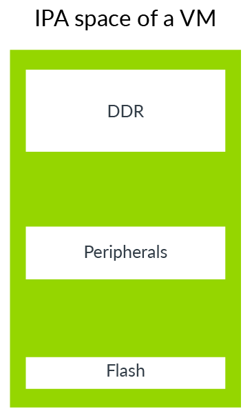
The VM can use peripheral regions to access both real physical
peripherals, which are often referred to as directly assigned
peripherals, and virtual peripherals.
Virtual peripherals are completely emulated in software by the hypervisor, as this diagram highlights:
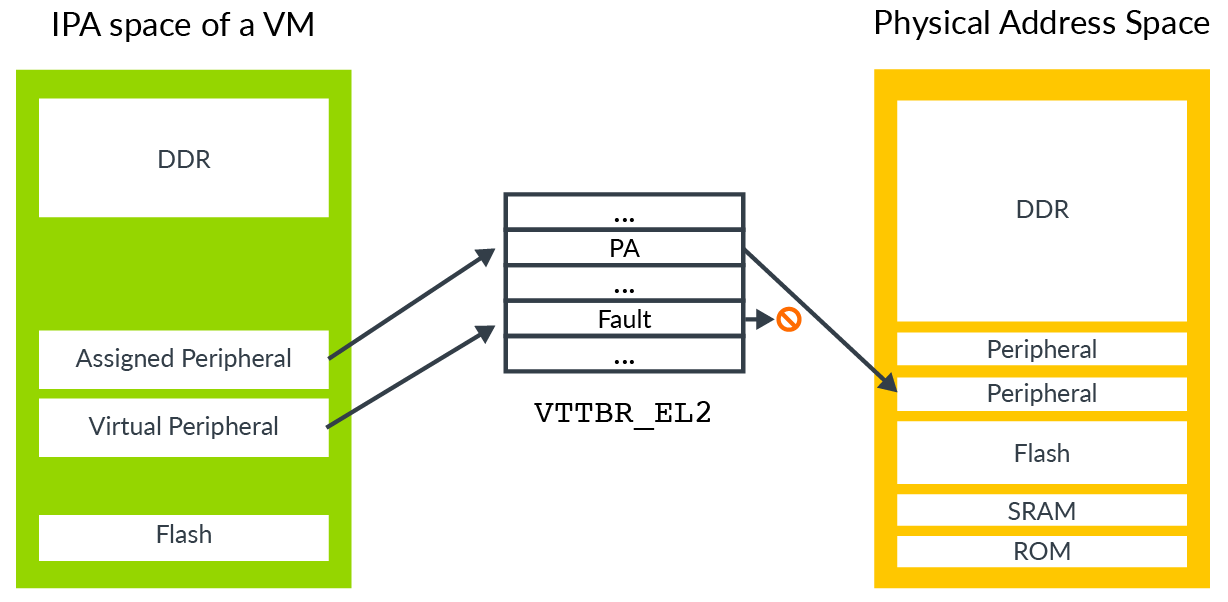
An assigned peripheral is a real physical device that has been allocated to the VM, and mapped into its IPA space. This allows software that is running within the VM to interact with the peripheral directly.
A virtual peripheral is one that the hypervisor is going to emulate in software. The corresponding stage 2 table entries would be marked as fault. Software in the VM thinks that it can talk directly to the peripheral, but each access triggers a stage 2 fault, with the hypervisor emulating the peripheral access in the exception handler.
To emulate a peripheral, a hypervisor needs to know not only which peripheral was accessed, but also which register in that peripheral was accessed, whether the access was a read or a write, the size of the access, and the registers used for transferring data.
Starting with the address, Exception Model introduces the FAR_ELx registers.
When dealing with stage 1 faults, these registers report the virtual
address that triggered the exception. A virtual address is not helpful
to a hypervisor, because the hypervisor would not usually know how the
Guest OS has configured its virtual address space. For stage 2 faults,
there is an additional register, HPFAR_EL2, which reports
the IPA of the address that aborted. Because the IPA space is
controlled by the hypervisor, it can use this information to determine
the register that it needs to emulate.
Exception Model shows how the ESR_ELx registers
report information about the exception. For single general-purpose
register loads or stores that trigger a stage 2 fault, additional
syndrome information is provided. This information includes the size of
the accesses and the source or destination register, and allows a
hypervisor to determine the type of access that is being made to the
virtual peripheral.
This diagram illustrates the process of trapping then emulating the access:
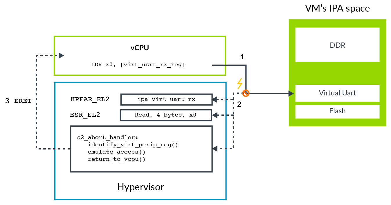
This process is described in these steps:
- Software in the VM attempts to access the virtual peripheral. In this example, this is the receive FIFO of a virtual UART.
- This access is blocked at stage 2 translation, leading to an abort routed to EL2.
- The abort populates
ESR_EL2with information about the exception, including the number of bytes accessed, the target register and whether it was a load or store. - The abort also populates
HPFAR_EL2with the IPA of the aborting access.
- The abort populates
- The hypervisor uses the information from
ESR_EL2andHPFAR_EL2to identify the virtual peripheral register accessed. This information allows the hypervisor to emulate the operation. It then returns to the vCPU via anERET.- Execution restarts on the instruction after the
LDR.
- Execution restarts on the instruction after the
System Memory Management Units (SMMUs)
So far, we have considered different types of access that come from the processor. Other masters in a system, such DMA controllers, might be allocated for use by a VM. We need some way to extend the stage 2 protections to those masters as well.
Consider a system with a DMA controller that does not use virtualization, as shown in the following diagram:
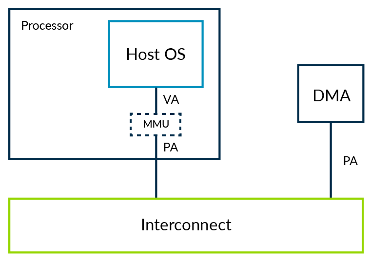
The DMA controller would be programmed via a driver, typically in kernel space. That kernel space driver can ensure that the OS level memory protections are not breached. This means that one application cannot use the DMA to get access to memory that it should not be able to see.
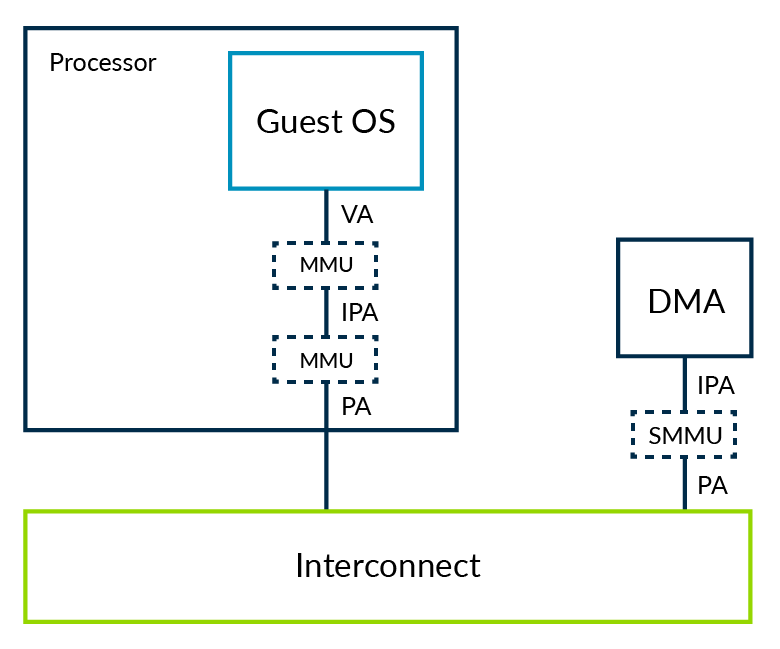
Let's consider the same system, but with the OS running within a VM, as shown in the following diagram:
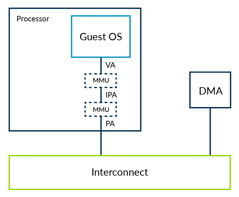
In this system, a hypervisor is using stage 2 to provide isolation between VMs. The ability of software to see memory is limited by the stage 2 tables that the hypervisor controls.
Allowing a driver in the VM to directly interact with the DMA controller creates two problems:
- Isolation: The DMA controller is not subject to the stage 2 tables, and could be used to breach the VM’s sandbox.
- Address space: With two stages of translation, what the kernel believes to be PAs are IPAs. The DMA controller still sees PAs, therefore the kernel and DMA controller have different views of memory. To overcome this problem, the hypervisor could trap every interaction between the VM and the DMA controller, providing the necessary translation.When memory is fragmented, this process is inefficient and problematic.
An alternative to trapping and emulating driver accessesis to extend the stage 2 regime to also cover other masters, such as our DMA controller. When this happens, those masters also need an MMU. This is referred to as a System Memory Management Unit (SMMU, sometimes also called IOMMU):
The hypervisor would be responsible for programming the SMMU, so that the upstream master, which is the DMA in our example, sees the same view of memory as the VM to which it is assigned.
This process solves both of the problems that we identified. The SMMU can enforce the isolation between VMs, ensuring that external masters cannot be used to breach the sandbox. The SMMU also gives a consistent view of memory to software in the VM and the external masters allocated to the VM.
Virtualization is not the only use case for SMMUs. There are many other cases that are not covered within the scope of this guide.
Trapping and emulation of instructions
Sometimes a hypervisor needs to emulate operations within a Virtual Machine (VM). For example, software within a VM might try to configure low level processor controls relating to power management or cache coherency. Typically, you do not want to give the VM direct access to these controls, because they could be used to break isolation, or to affect other VMs in your system.
A trap causes an exception when a given action, such as reading a register, is performed. A hypervisor needs the ability to trap operations, like the ones that configure low level controls, in a VM and emulate them, without affecting other VMs.
The architecture includes trap controls for you to trap operations in a VM and emulate them. When a trap is set, performing a specific action that would normally be allowed causes an exception to a higher Exception level. A hypervisor can use these traps to emulate operations within a VM.
For example, executing a Wait For Interrupt (WFI) instruction usually puts the CPU into a low power state. By asserting the TWI bit, if HCR_EL2.TWI==1, then executing WFI at EL0 or EL1 will instead cause an exception to EL2.
Note: Traps are not just for virtualization. There are EL3 and EL1 controlled traps as well. However, traps are particularly useful to virtualization software. This guide only discusses the traps that are typically associated with virtualization.
In our WFI example, an OS would usually execute a WFI
as part of an idle loop. With a Guest OS within a VM, the hypervisor
can trap this operation and schedule a different vCPU instead, as this
diagram shows:

Presenting virtual values of registers
Another example of using traps is to present virtual values of registers. For example, ID_AA64MMFR0_EL1
reports support for memory system-related features in the processor. An
OS might read this register as part of boot, to determine which
features within the kernel to enable. A hypervisor might want to present
a different value, called a virtual value, to the Guest OS.
To do this, the hypervisor enables the trap that covers reads of the
register. On a trap exception, the hypervisor determines which trap was
triggered, and then emulates the operation. In this example, the
hypervisor populates the destination register with the virtual value of ID_AA64MMFR0_EL1, as shown here:
 Traps can also be used as part of lazy context switching. For example, an OS will typically initialize the Memory Management Unit (MMU) configuration registers (
TTBR<n>_EL1, TCR_EL1 and MAIR_EL1)
during boot, and then will not reprogram them again. A hypervisor can
use this to optimize its context switching routine, by only restoring
the registers on a context switch and not saving them.
However, the OS might do something unusual and reprogram the
registers after boot. To avoid this causing any problems, the hypervisor
can set the HCR_EL2.TVM trap. This setting causes any
write to the MMU related registers to generate a trap into EL2, which
allows the hypervisor to detect whether it needs to update its saved
copies of those registers.
Note: The architecture uses the terms trapping and routing for separate, but related, concepts. To recap, a trap causes an exception when a given action, such as reading a register, is performed. Routing refers to the Exception level that an exception is taken to once it has been generated.
MIDR and MPIDR
Using a trap to virtualize an operation requires significant
computation. The operation generates a trap exception to EL2, and the
hypervisor determines the desired operation, emulates it and then
returns to the guest. Feature registers, such as ID_AA64MMFR0_EL1,
are not frequently accessed by operating systems. This means that the
computation is acceptable when trapping accesses to these registers into
a hypervisor to emulate a read.
For registers that are accessed more frequently, or in performance critical code, you want to avoid such compute load. Examples of these registers and their values include:
MIDR_EL1. The type of processor, for example Cortex-A53MPIDR_EL1. The affinity, for example core 1 of processor 2
A hypervisor might want a Guest OS to see the virtual values of these registers, without having to trap each individual access. For these registers, the architecture provides an alternative to trapping:
VPIDR_EL2. This is the value to return for EL1 reads ofMIDR_EL1.VMPIDR_EL2. This is the value to return for EL1 reads ofMPIDR_EL1.
The hypervisor can setup these registers before entering the VM. If software running within the VM reads MIDR_EL1 or MPIDR_EL1, the hardware will automatically return the virtual value, without the need for a trap.
Note: VMPIDR_EL2 and VPIDR_EL2
do not have defined reset values. They must be initialized by start-up
code before entering EL1 for the first time. This is especially
important in bare metal environments.
Virtualizing exceptions
Interrupts are used by hardware in the system to signal events to software. For example, a GPU might send an interrupt to signal that it has completed rendering a frame.
A system that uses virtualization is more complex. Some interrupts might be handled by the hypervisor itself. Other interrupts might come from devices allocated to a Virtual Machine (VM), and need to be handled by software within that VM. Also, the VM that is targeted by an interrupt might not be running at the time that the interrupt is received.
This means that you need mechanisms to support the handling of some interrupts in EL2 by the hypervisor. You also need mechanisms for forwarding other interrupts to a specific VM or specific Virtual CPU (vCPU) within a VM.
To enable these mechanisms, the architecture includes support for virtual interrupts: vIRQs, vFIQs, and vSErrors. These virtual interrupts behave like their physical counterparts (IRQs, FIQs, and SErrors), but can only be signaled while executing in EL0 and EL1. It is not possible to receive a virtual interrupt while executing in EL2 or EL3.
Note: To recap, support for virtualization in Secure state was introduced in Armv8.4-A. For a virtual interrupt to be signaled in Secure EL0/1, Secure EL2 needs to be supported and enabled. Otherwise virtual interrupts are not signaled in Secure state.
Enabling virtual interrupts
To signal virtual interrupts to EL0/1, a hypervisor must set the corresponding routing bit in HCR_EL2. For example, to enable vIRQ signaling, a hypervisor must set HCR_EL2.IMO. This setting routes physical IRQ exceptions to EL2, and enables signaling of the virtual exception to EL1.
Virtual interrupts are controlled per interrupt type. In theory, a VM could be configured to receive physical FIQs and virtual IRQs. In practice, this is unusual. A VM is usually configured only to receive virtual interrupts.
Generating virtual interrupts
There are two mechanisms for generating virtual interrupts:
- Internally by the core, using controls in
HCR_EL2. - Using a GICv2, or later, interrupt controller.
Let's start with mechanism 1. There are three bits in HCR_EL2 that control virtual interrupt generation:
VI= Setting this bit registers a vIRQ.VF= Setting this bit registers a vFIQ.VSE= Setting this bit registers a vSError.
Setting one of these bits is equivalent to an interrupt controller
asserting an interrupt signal into the vCPU. The generated virtual
interrupt is subject to PSTATE masking, just like a regular interrupt.
This mechanism is simple to use, but the disadvantage is that it only provides a way to generate the interrupt itself. The hypervisor is then required to emulate the operation of the interrupt controller in the VM. To recap, trapping and emulating operations in software involve overhead that is best avoided for frequent operations such as interrupts.
The second option is to use Arm's Generic Interrupt Controller (GIC) to generate virtual interrupts. From Arm GICv2, the GIC can signal both physical and virtual interrupts, by providing a physical CPU interface and a virtual CPU interface, as shown in the following diagram:

These two interfaces are identical, except that one signals physical interrupts and the other one signals virtual interrupts. The hypervisor can map the virtual CPU interface into a VM, allowing software in that VM to communicate directly with the GIC. The advantage of this approach is that the hypervisor only needs to set up the virtual interface, and does not need to emulate it. This approach reduces the number of times that the execution needs to be trapped to EL2, and therefore reduces the overhead of virtualizing interrupts.
Note: Although Arm GICv2 can be used with Armv8-A designs, it is more common to see GICv3 or GICv4 used.
Example of forwarding an interrupt to a vCPU
So far, we have looked at how virtual interrupts are enabled and generated. Let's see an example that shows the forwarding of a virtual interrupt to a vCPU. In this example, we will consider a physical peripheral that has been assigned to a VM, as shown in the following diagram:

The diagram illustrates these steps:
- The physical peripheral asserts its interrupt signal into the GIC.
- The GIC generates a physical interrupt exception, either IRQ or FIQ, which gets routed to EL2 by the configuration of
HCR_EL2.IMO/FMO. The hypervisor identifies the peripheral and determines that it has been assigned to a VM. It checks which vCPU the interrupt should be forwarded to. - The hypervisor configures the GIC to forward the physical interrupt as a virtual interrupt to the vCPU. The GIC will then assert the vIRQ or vFIQ signal, but the processor will ignore this signal while it is executing in EL2.
- The hypervisor returns control to the vCPU.
- Now that the processor is in the vCPU (EL0 or EL1), the virtual
interrupt from the GIC can be taken. This virtual interrupt is subject
to the
PSTATEexception masks.
The example shows a physical interrupt being forwarded as a virtual interrupt. The example matches the assigned peripheral model described in the section on stage 2 translation. For a virtual peripheral, a hypervisor can create a virtual interrupt without linking it to a physical interrupt.
Interrupt masking and virtual interrupts
In Exception Model, we introduce the interrupts mask bits in PSTATE, PSTATE.I for IRQs, PSTATE.F for FIQs and PSTATE.A for SErrors. When operating within a virtualized environment, these masks work in a slightly different way.
For example, for IRQs we have already seen that setting HCR_EL2.IMO does two things:
- Routes physical IRQs to EL2
- Enables signaling of vIRQs in EL0 and EL1
This setting also changes the way that the PSTATE.I mask is applied. While in EL0 and EL1, if HCR_E2.IMO==1, PSTATE.I operates on vIRQs not pIRQs.
Virtualizing the Generic Timers
The Arm architecture includes the Generic Timer, which is a standardized set of timers available in each processor. The Generic Timer consists of a set of comparators that compare against a common system count. A comparator generates an interrupt when its value is equal to or less than the system count. In the following diagram, we can see the Generic Timer in a system (orange), and its components of comparators and a counter module.

The following diagram shows an example system with a hypervisor that hosts two virtual CPUs (vCPUs):

Note: In the example, we ignore the overhead of running the hypervisor to context switch between the vCPUs.
After 4ms of physical time, or wall-clock time, each vCPU has run for 2ms. If vCPU0 had set up its comparator at T=0 to generate an interrupt after 3ms, would you expect the interrupt to have fired?
Alternatively, do you want an interrupt after 2ms of virtual time, which is time experienced by the vCPU, or after 2ms of wall-clock time?
The Arm architecture provides the ability to do both, depending on what virtualization is being used for. Let's see how it does this.
Software running on a vCPU has access to two timers:
- EL1 Physical Timer
- EL1 Virtual Timer
The EL1 Physical Timer compares against the count generated by the system counter module. Using this timer gives wall-clock time.
The EL1 Virtual Timer compares against a virtual count. The virtual count is the physical count minus an offset. The hypervisor specifies the offset for the currently scheduled vCPU in a register. This allows it to hide the passage of time while the vCPU was not scheduled to run:

To illustrate this concept, we can extend the earlier example as shown in the following diagram:

Over a period of 6ms, each vCPU gets to run for 3ms. A hypervisor could use the offset register to present a virtual count that only shows time the vCPU was running. Or the hypervisor could keep the offset at 0, which would mean that virtual time was the same as physical time.
Note: The example shows the frequency of the System Count as 1ms. In practice, this frequency value is very unlikely. We recommend that you set the System Count to use a frequency of between 1MHz and 50MHz.
Virtualization Host Extensions
The following diagram shows a simplified version of the software stack and Exception level that we looked at in the section on virtualizing exceptions:
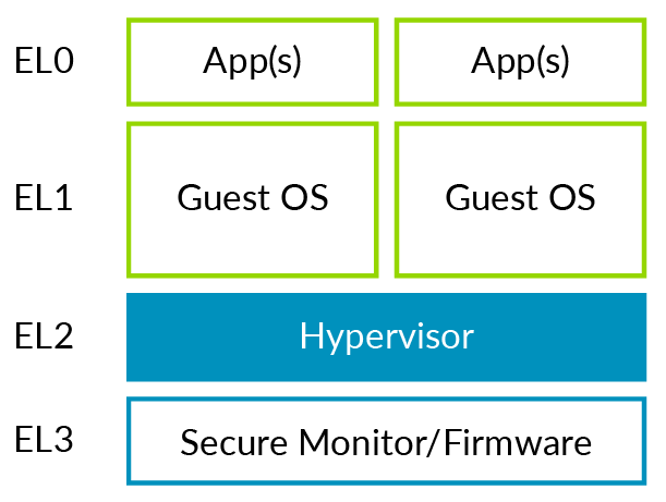
You can see how a standalone hypervisor maps to the Arm Exception levels. The hypervisor is running at EL2 and the virtual machines (VMs) at EL0/1. This situation is more problematic for hosted hypervisors, as shown in the following diagram:
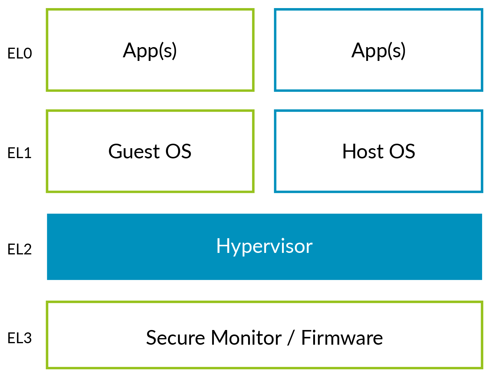
Traditionally, kernels run at EL1, but the virtualization controls are in EL2. This means that most of the Host OS is at EL1, with some stub code running in EL2 to access the virtualization controls. This arrangement can be inefficient, because it may involve additional context switching.
The kernel will need to handle some differences between running at EL1 and EL2, but these are restricted to a small number of subsystems, for example early boot.
Note: The DynamIQ processors (Cortex-A55, Cortex-A75 and Cortex-A76) support Virtualization Host Extensions (VHEs).
Running the Host OS at EL2
VHE is controlled by two bits in HCR_EL2. These bits can be summarized as:
E2H: Controls whether VHE is enabled.TGE: When VHE is enabled, controls whether EL0 is Guest or Host.
The following table summarizes the typical settings:
|
Executing in:
|
HCR_EL2
|
|
E2H
|
TGE
|
|
| Guest kernel (EL1) | 1 | 0 |
| Guest application (EL0) | 1 | 0 |
| Host kernel (EL2) | 1 | 1* |
| Host application (EL0) | 1 | 1 |
* On an exception that exits from a VM into the hypervisor, TGE would initially be 0. Software would have to set the bit before running the main part of the host kernel.
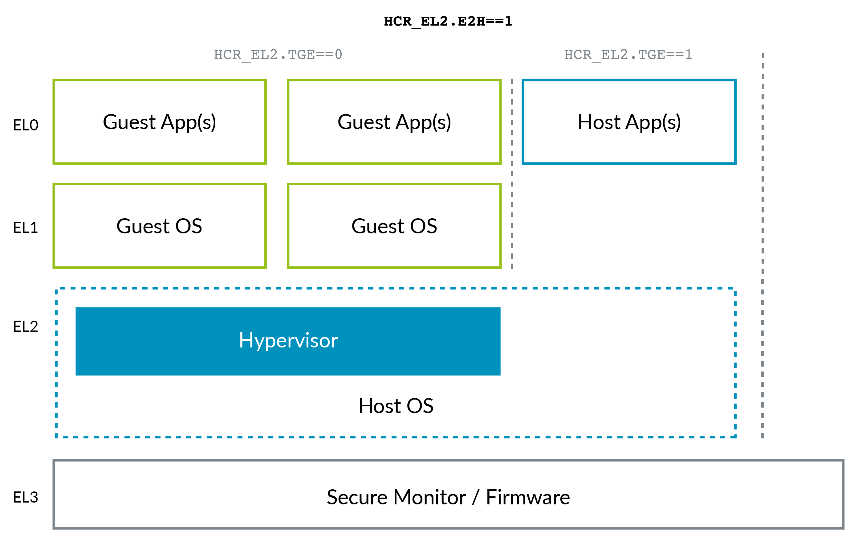
You can see these typical settings in the following diagram:
Virtual address space
The following diagram shows what the virtual address spaces of EL0/EL1 looked like before VHE was introduced:
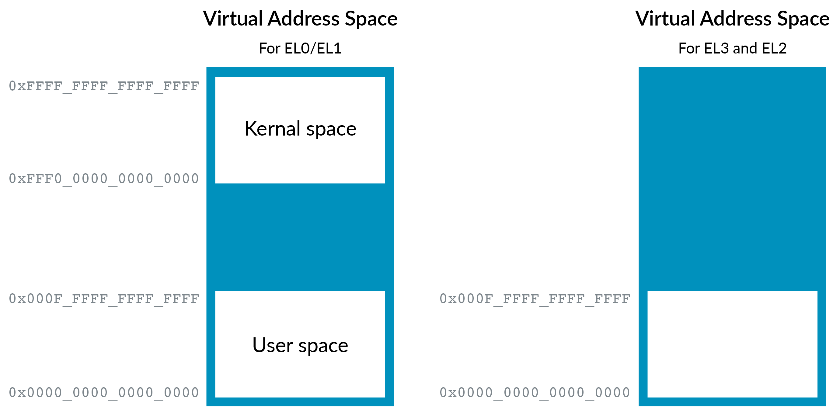
As discussed in Memory Management, EL0/1 has two regions. By convention, the upper region is referred to as kernel space, and the lower region is referred to as user space. However, EL2 only has a single region at the bottom of the address range. This difference is because, traditionally, a hypervisor would not host applications. This means that the hypervisor does not need a split between kernel space and user space.
Note: The allocation of kernel space to the upper region, and user space to the lower region, is simply a convention. It is not mandated by the Arm architecture.
The EL0/1 virtual address space also supports Address Space Identifiers (ASID), but EL2 does not. This is because the hypervisor would not usually host applications.
To allow our Host OS to execute efficiently in EL2, we need to add the second region and ASID support. Setting HCR_EL2.E2H addresses these issues, as you can see in the following diagram:
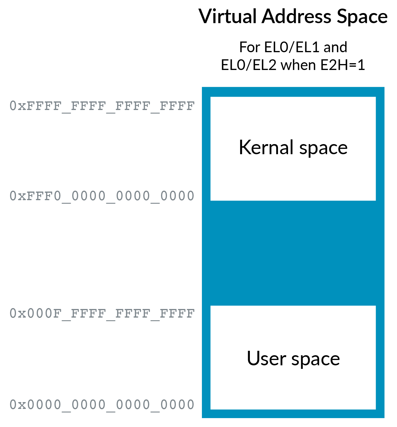
While in EL0, HCR_EL2.TGE controls which virtual address
space is used: either the EL1 space or the EL2 space. Which space is
used depends on whether the application is running under the Host OS (TGE==1) or the Guest OS (TGE==0).
Re-directing register accesses
We saw in the section on Virtualizing generic timers that enabling
VHE changes the layout of the EL2 virtual address space. However, we
still have a problem with the configuration of the MMU. This is because
our kernel will try to access _EL1 registers, such as TTBR0_EL1, rather than _EL2 registers such as TTBR0_EL2.
To run the same binary at EL2, we need to redirect the accesses from the EL1 registers to the EL2 equivalents. Setting E2H will do this, so that accesses to _EL1 system registers are redirected to their EL2 equivalents. This redirection illustrated in the following diagram:

However, this redirection leaves us with a new problem. A hypervisor still needs access to the real _EL1 registers, so that it can implement task switching. To resolve this, a new set of register aliases are introduced with an _EL12 or _EL02 suffix. When used at EL2, with E2H==1, these give access to the EL1 register for context switching. You can see this in the following diagram:

Exceptions
Usually, the HCR_EL2.IMO/FMO/AMO bits control whether physical exceptions are routed to EL1 or EL2. When executing in EL0 with TGE ==1, all physical exceptions are routed to EL2, unless they are routed to EL3 by SCR_EL3.
This is the case regardless of the actual values of the HCR_EL2 routing
bits. This is because the application is executing as a child of the
Host OS, and not a Guest OS. Therefore, any exceptions should be routed
to the Host OS that is running in EL2.
Nested virtualization
In theory, a hypervisor can be run within a virtual machine (VM). This concept is called nested virtualization:
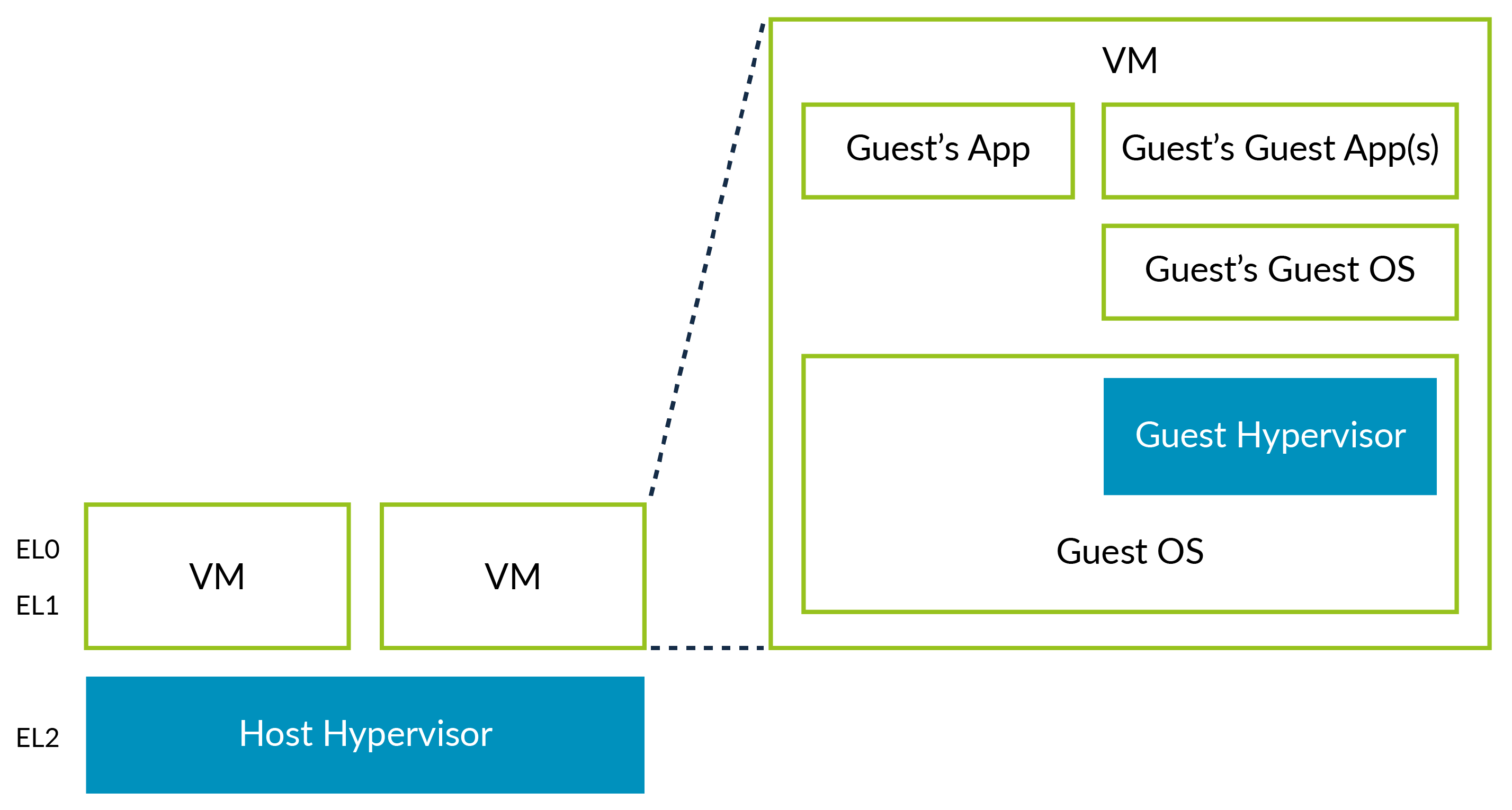
We refer to the first hypervisor as the Host Hypervisor, and the hypervisor within the VM as the Guest Hypervisor.
Before the release of Armv8.3-A, it was possible to run a Guest Hypervisor in a VM by running the Guest Hypervisor in EL0. However, this required a significant amount of software emulation, and was both complicated to implement and resulted in poor performance. With the features added in Armv8.3-A, it is possible to run the Guest Hypervisor in EL1. With the features added in Armv8.4-A, this process is even more efficient, although it still involves extra intelligence in the Host Hypervisor.
Guest Hypervisor access to virtualization controls
We do not want to give a Guest Hypervisor direct access to the virtualization controls. This is because giving direct access could potentially allow the VM to breach its sandbox, or to discover information about the host platform. This potential problem is similar to the issues demonstrated in the previous examples on trapping and emulating.
Guest Hypervisors run at EL1. New controls in HCR_EL2 allow the Host Hypervisor to trap the attempts of the Guest Hypervisor to access the virtualization controls:
HCR_EL2.NVEnables hardware support for nested virtualizationHCR_EL2.NV1Enables an extra set of trapsHCR_EL2.NV2Enables re-direction to memoryVNCR_EL2When NV2==1, points to a structure in memory
Armv8.3-A added the NV and NV1 controls. Accesses to _EL2 registers from EL1 are usually undefined, and accesses would cause an exception to EL1. The NV and NV1 bits cause EL1 accesses to _EL2
registers to trap to EL2 instead. This allows a Guest Hypervisor to run
at EL1, with the Host Hypervisor at EL2 emulating some of its
operations. NV also traps ERETs from EL1.
The following diagram shows a Guest Hypervisor setting up and entering a VM:
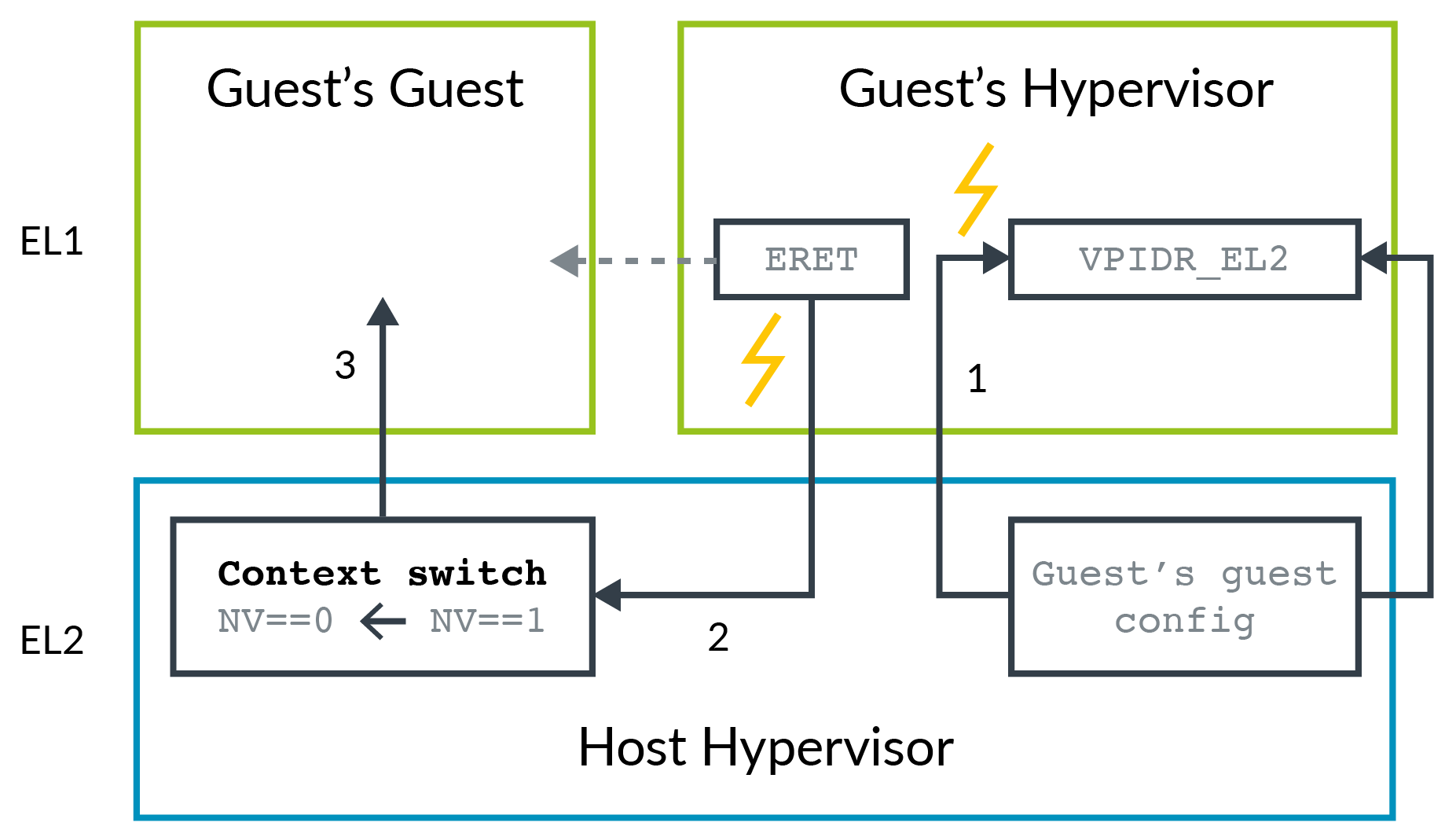
- Accesses to
_EL2register by the Guest Hypervisor are trapped to EL2. The Host Hypervisor records the configuration that the Guest Hypervisor is setting up. - The Guest Hypervisor attempts to enter its Guest VM (the Guest VM of the Guest), and the
ERETis trapped to EL2 - The Host Hypervisor retrieves the configuration for the Guest of
the Guest and loads this configuration into the appropriate registers.
Then the host hypervisor clears the
NVbit and enters the Guest of the Guest.
The problem with this approach is that each individual access to an EL2 register by the Guest Hypervisor must be trapped. Many registers are accessed when task switching between two vCPUs or VMs, and result in many traps. Each trap has the overhead of an exception entry and return.
A better solution is to capture the configuration of the EL2 registers, and only trap to the Host Hypervisor on the ERET. This solution is possible with Armv8.4-A. When NV2 is set, EL1 accesses to _EL2
registers are redirected to a structure in memory. The Guest
Hypervisor can read and write the registers as many times as it needs
to, without a single trap. The ERET still traps to EL2, at which time the Host Hypervisor can re-retrieve the configuration from memory.
The following diagram illustrates this concept:
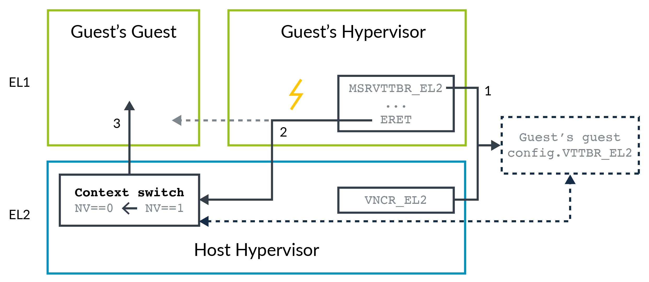
- Accesses to
_EL2registers from the Guest Hypervisor in EL1 are redirected to a structure in memory. The location of the structure is specified by Host Hypervisor usingVNCR_EL2 - The Guest Hypervisor attempts to enter its Guest VM, which is the Guest VM of the Guest, and the
ERETis trapped to EL2. - The Host Hypervisor retrieves the configuration for the Guest of the Guest, and loads them into the appropriate registers. The host hypervisor then clears the NV bit and enters the Guest of the Guest.
The advantage to this approach is that there are fewer traps, and therefore fewer entries into the Host Hypervisor.
Secure virtualization
Virtualization was introduced in Armv7-A. At that time, Hyp mode, which is the equivalent to EL2 in AArch32, was only available in Non-secure state. When Armv8.4-A was introduced, support for EL2 in Secure state was added as an optional feature.
When a processor supports Secure EL2, the processor needs to be enabled from EL3 using the SCR_EL3.EEL2 bit. Setting this bit enables entry into EL2, and enables use of the virtualization features in Secure state.
Before Secure virtualization was available, EL3 was usually used to host a mixture of Security state switching software and platform firmware. This is because we like to minimize the amount of software in EL3, so that EL3 easier to secure. Secure virtualization allows us to move the platform firmware into EL1. Virtualization provides separate secure partitions for the platform firmware and trusted kernels. The following diagram illustrates this point:

Secure EL2 and the two Intermediate Physical Address spaces
The Arm architecture defines two physical address spaces: Secure and Non-secure. In Non-secure state, the output of the stage 1 translation of a virtual machine (VM) is always Non-secure. Therefore, there is a single Intermediate Physical Address (IPA) space for stage 2 to handle.
In Secure state, the stage 1 translation of a VM can output both Secure and Non-secure addresses. The NS bit in the translation table descriptors controls whether the Secure or the Non-secure address space is outputted. As shown in the following diagram, this means that there are two IPA spaces for stage 2, Secure and Non-secure:

Unlike the stage 1 tables, there is no NS bit in the stage 2 table entries. For a particular IPA space, all translations result in either a Secure Physical Address or a Non-secure Physical Address. This translation is controlled by a register bit. Typically, the Non-secure IPAs translate to Non-secure PAs, and the Secure IPAs translate to Secure PAs.