Chapter 1: Hello, Game Graphics
Chapter 4: Translucency and Depth
Chapter 6: Cameras and Coordinates
Chapter 7: Your First 3D Project
Chapter 9: Your First Lighting Model
Chapter 11: Cubemaps And Skyboxes
Chapter 14: Optimizing Shaders
Chapter 16: Writing Shaders in Unity
Chapter 17: Writing Shaders in UE4
Chapter 18: Writing Shaders in Godot
Chapter 1: Hello, Game Graphics
What Is Rendering?
What Is a Mesh?
Meshes are one of the methods we have for describing shapes in a way that will make sense to a computer. To define a shape, a mesh needs to store information about three things: vertices, edges, and faces
Vertices are points in 3D space.
Edges are the lines that connect the vertices
Faces are 2D shapes formed by three or more edges. You can think of faces as the space in between the edges of a mesh

Only a mesh’s vertices are stored in memory, and the edges and faces of a mesh are defined implicitly by the order the vertices are in

Which side of a face is the front is important because many games won’t render the “back” side of mesh faces. This is an optimization known as backface culling, and is a common optimization used in games
Vectors 101
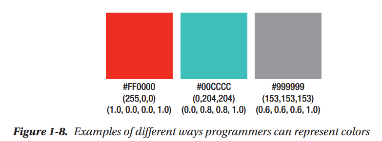
Defining a Colorl in Computer Graphics
The Rendering Pipeline
What Is a Shader?
Summary
Chapter 2: Your First Shaders
Setting Things Up on Windows
Setting Up Our Project
Creating Your First Triangle
Your First Vertex Shader
The #version Preprocessor Directive
GLSL's in Keyword
GLSL's vec Data Types
Writing to gl_Position
Normalized Device Coordinates
Your First Fragment Shader
GLSL's out Keyword
Using Shaders in Our Project
Adding Color with Vertex Attributes
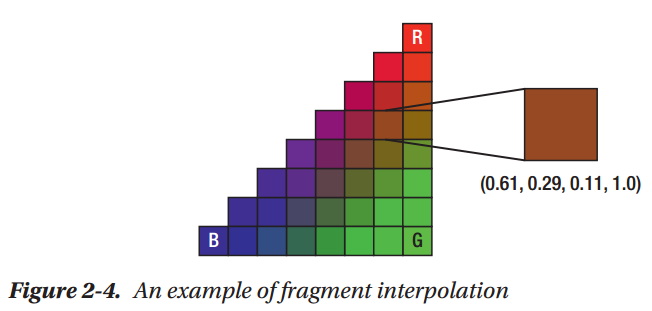
Introducing Fragment Interpolation
Summary
Chapter 3: Using Textures
Making a Quad
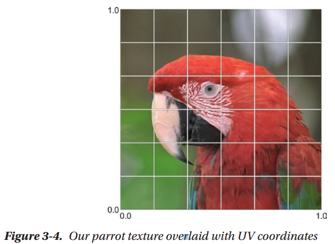
Introducing UV Coordinates
Using Textures in Shaders
Scrolling UV Coordinates
Adjusting Brightness with a Uniform
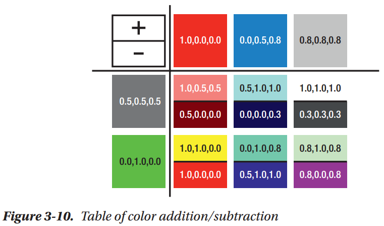
Basic Color Math
Mixing Textures with the "Mix" Instruction
Summary
Chapter 4: Translucency and Depth
Example Project Setup
Drawing Our Little Green Man
Alpha Testing with Discard

Building a Scene with Depth Testing
Creating Clouds with Alpha Blending
GLSL's min() and max() Functions
How Alpha Blending Works
Adding Some Sun with Additive Blending
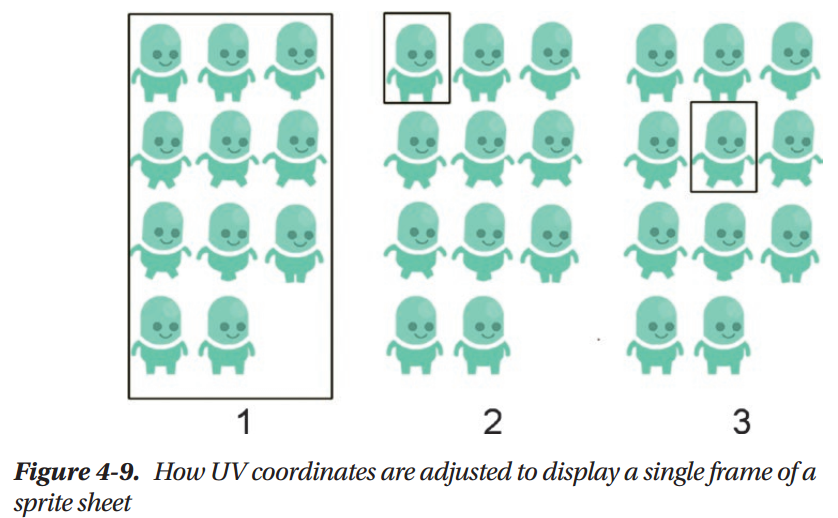
Animating with Sprite Sheets
Summary
Chapter 5: Making Things Move
Making Our Character Walk Forward
Scaling Our Cloud in Shader Code
Rotating Objects with a Vertex Shader
Introducing Transformation Matrices
Animating a Transformation Matrix
The Identity Matrix
Summary
Chapter 6: Cameras and Coordinates
Using a View Matrix
Transform Matrices and Coordinate Spaces
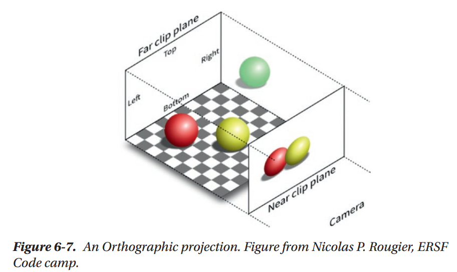
Camera Frustums and Projections
Summary
Chapter 7: Your First 3D Project
Loading a Mesh
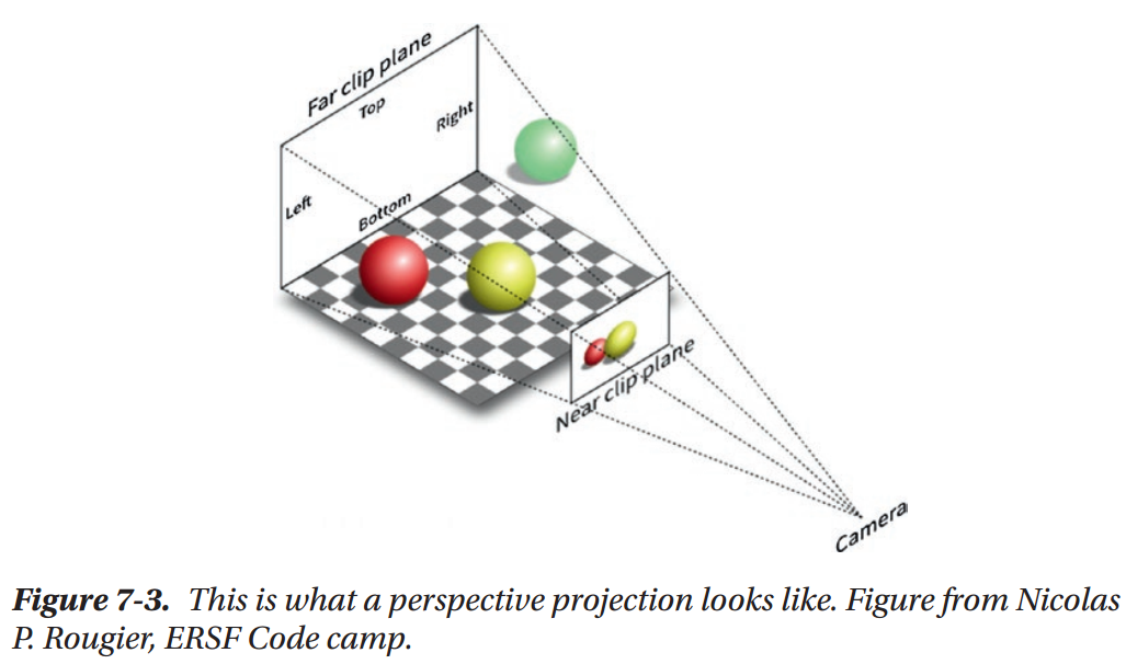
Making a Perspective Camera
Summary
Chapter 8: Diffuse Lighting
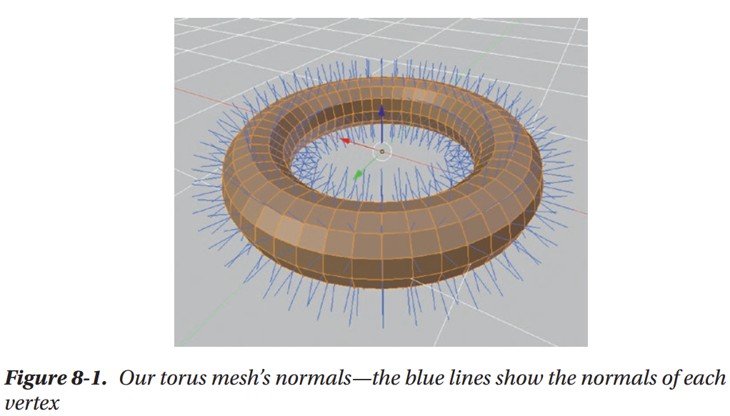
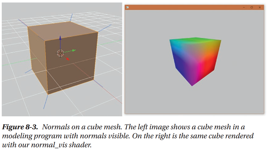
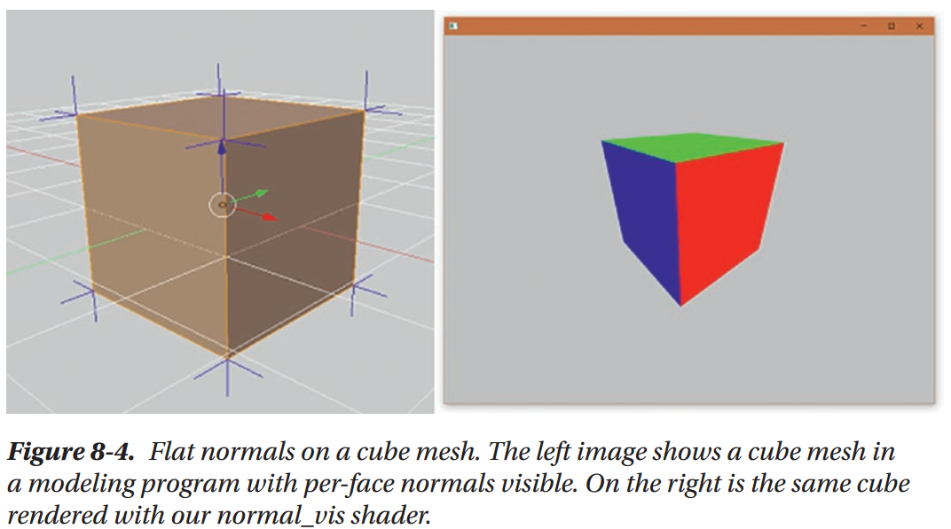
Smooth vs. Flat Shading with Normals
World Space Normals and Swizzling
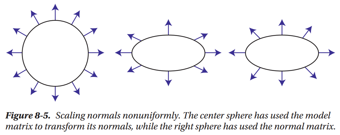
The Normal Matrix
Why Lighting Calculations Need Normals
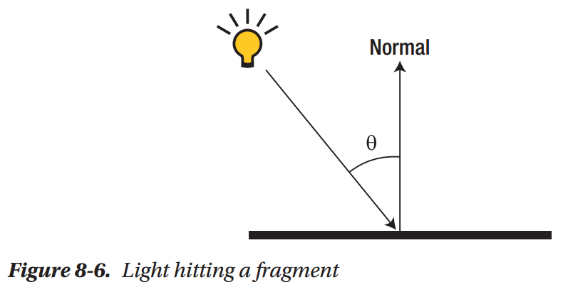
Normals are essential to lighting calculations because they allow us to figure out the relationship between the direction of light that’s hitting our mesh’s surface and the orientation of that surface itself. We can think of every fragment on a mesh as being a tiny, completely flat point, regardless of the overall shape of the mesh. Using this mental model, light hitting a fragment can be thought about like Figure 8-6.
What's a Dot Product?
Shading with Dot Products
Your First Directional Light
Creating a Rim Light Effect
Summary
Chapter 9: Your First Lighting Model
Specular Lighting
Your First Specular Shader
Combining Diffuse and Specular Light
Ambient Lighting
The Phong Lighting Model
Blinn-Phong Lighting
Using Textures to Control Lighting
Summary
Chapter 10: Normal Mapping
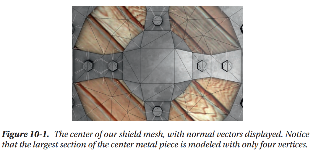
Notice that the very center metal portion of our shield mesh consists of very few vertices. What would happen if we wanted that area to be covered with small scratches, or bumps, like you might expect from a shield made of unpolished metal? The central square of the shield is made up of only four vertices total, which means that without adding more vertices to our mesh, we’re incapable of adding these sorts of small details in actual mesh geometry. We could add more vertices to let us model more detail, but the more vertices a mesh has, the more vertex shader calculations need to be performed to render the mesh and the more memory the mesh takes up. Most games can’t afford to add thousands of vertices to every object just for bumps and scratches.
To get around this problem, games use a special kind of texture map, called a normal map, to store normal vectors in the same way that our spec map texture stores information about our surface’s shininess. Since there are many more pixels in our normal map texture than there are vertices in our mesh, this gives us a way to store many more normal vectors than we can with just our geometry. 
What Is a Normal Map?
A normal map is a texture that stores normalized vectors instead of colors in each pixel. This means that the RGB value of each pixel in a normal map texture is really the XYZ value of a normal vector that we can use in our lighting calculations
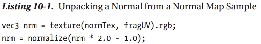
However, textures have no way to represent values less than 0, since there’s no such thing as a negative color. This would normally mean that we would only be able to store vectors with positive components, but this would make normal maps almost useless for storing normal vectors, since it would severely limit the directions that could be stored. To work around this, normal maps treat the value 0.5 as 0.0. This means that a pixel with the color (0, 0.5, 1) represents the vector (-1, 0, 1). The side effect of this is that we have to do some additional shader math after sampling a normal map, to convert the color value to the desired vector direction.
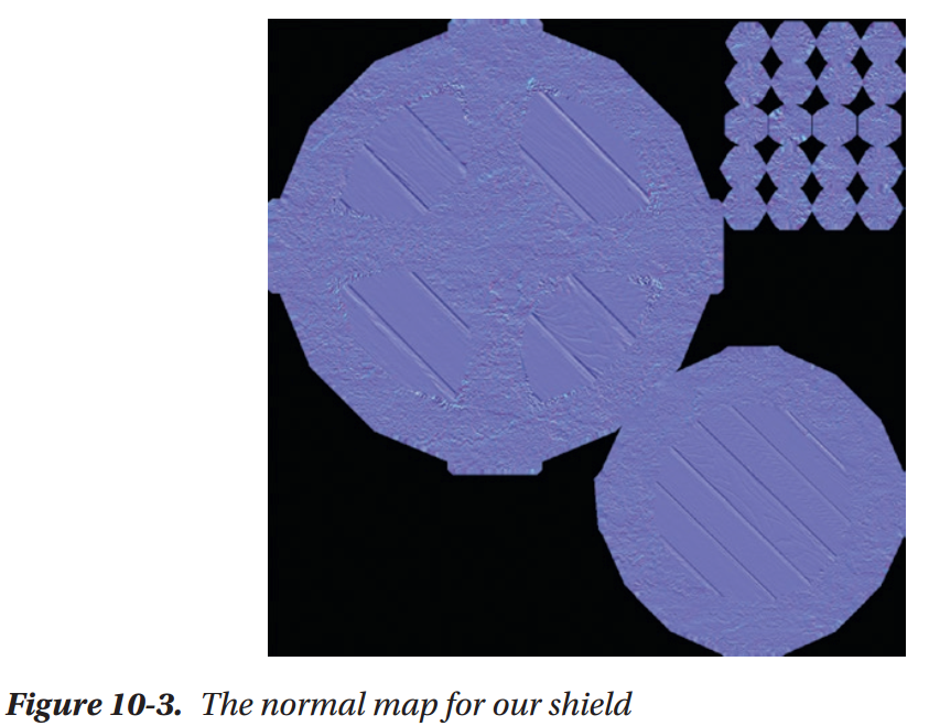
You may have seen normal maps before; they usually have a blueish tint to them. For instance, the normal map we’re going to use on our shield is shown in Figure 10-3. This blue tint is because the blue channel of every pixel in a normal map corresponds to the Z value of the vectors being stored in the texture. Normal mapping uses a special coordinate space called tangent space, which is defined relative to the surface of our mesh. For any given point, the Z axis in tangent space points in the direction of the mesh geometry’s normal vector. Since the normal that we provide in a normal map will also point away from the surface of the mesh, this means that every normal vector we store will have a positive Z value, resulting in every pixel having a blue value greater than 0.5.
Figure 10-3 shows the kinds of surface details that normal mapping is commonly used to provide. If you look closely, you can see the bumpy surface of the metal areas of our mesh, and the grain of the wood. These kinds of small details would take thousands of triangles to render convincingly, but are handled easily by normal mapping.
Introducing Tangent Space
Tangent space is one of the weirder coordinate spaces out there, because it’s a perfragment coordinate space. Rather than being based on the orientation of the camera or the position of an object, it’s defined relative to the surface of the mesh that each fragment is from.
We already know that the Z axis in tangent space always points in the direction of the normal vector that we get from our mesh’s geometry, so all that’s left is for us to figure out what the other two axes are. The X axis of tangent space comes from our mesh’s tangent
vectors. Tangent vectors are stored on each vertex of our mesh, just like vertex colors or normal vectors, and store the direction of the U axis of our mesh’s UV coordinates. The Y axis of tangent space is known as the bitangent, which is a vector that is perpendicular to
both the tangent and normal vectors. The bitangent is usually calculated in shader code, rather than stored in mesh memory. Put together, these three vectors create the axes of a coordinate space that is oriented to the current fragment being processed.

From the diagram, it may look as though we could use any set of perpendicular vectors for the tangent and bitangent directions, but it’s important that they are aligned with our UV coordinate directions so that our normal mapping calculations match up with the texture samples for a given fragment.
You might be wondering why we’re storing our normal vectors in this weird coordinate space at all, rather than just storing the vectors in a normal map in object space. Some games do choose to work with object space normal maps, rather than the more typical tangent space ones that we’ve seen so far. However, object space normal maps have several limitations, like not supporting mesh animations, and not allowing artists to reuse UV coordinates for different parts of a mesh. These limitations have led most games to opt for tangent space normal maps despite the increased complexity, so that normal mapping can be applied to the widest range of meshes possible.
Working with Tangent Vectors
Introducing Cross Products
How Normal Mapping Works
Writing a Water Shader
There's More to Normal Mapping
Summary
Chapter 11: Cubemaps And Skyboxes
What Is a Cubemap?
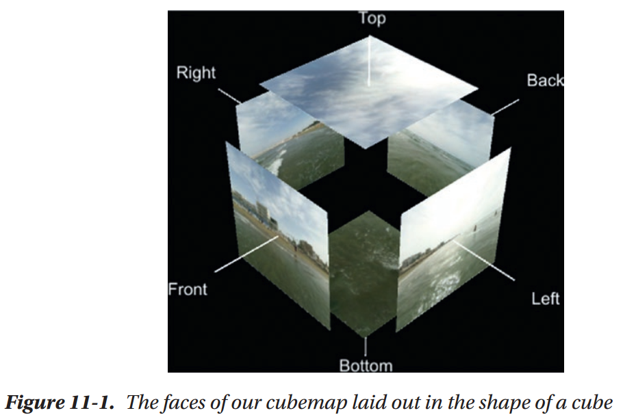
A cubemap is a special kind of texture, and what makes it special is that it’s made up of a combination of six individual textures stored in memory in a way that lets us treat them as though they’re a single object. Cubemaps get their name because each of these six textures is treated as though they are one of the faces of a cube
Loading a Cubemap in openFrameworks
Rendering a Cubemap on a Cube
Introducing Skyboxes
A skybox is a large cube that is always positioned in the same place that the camera is. This means that the camera will always be located inside of the cube, and the cube will not appear to move if the camera is translated. A cubemap is applied to the faces of the cube that face inward, so that wherever the camera looks, rather than seeing a background color, it will see a cubemap texture instead.
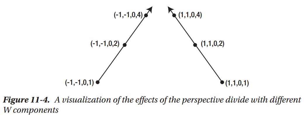
The Perspective Divide
Skyboxes and the Perspective Divide
Finishing Our Skybox
Creating Cubemap Reflections
There's More to Cubemaps
Summary
Chapter 12: Lighting in Depth
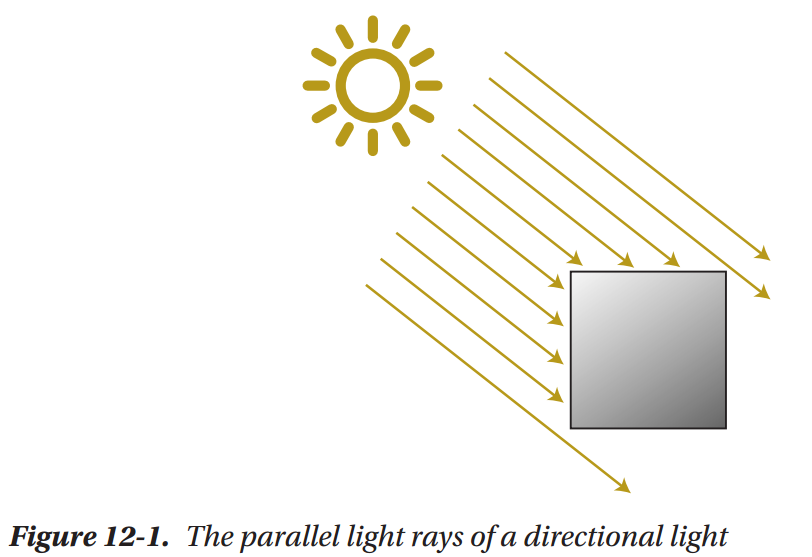
Directional Lights
Point Lights

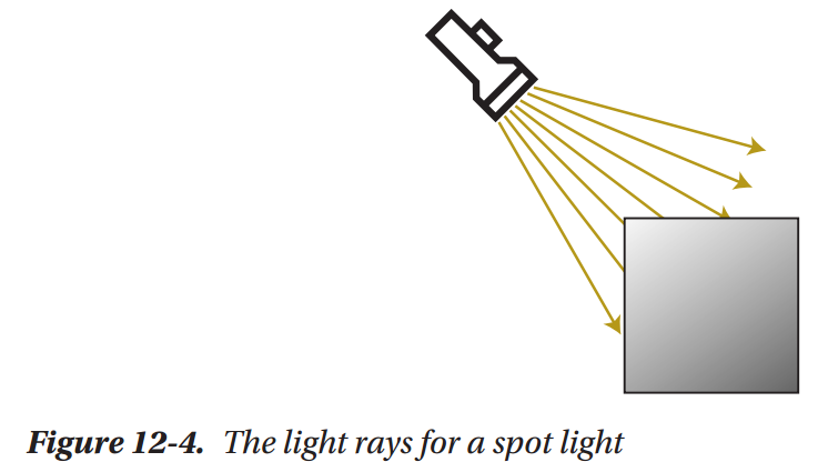
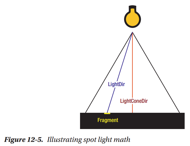
Spot Lights
Multiple Light Sources
A More Flexible Multi-light Setup
Taking Things Farther
Summary
Chapter 13: Profiling Shaders
How to Measure Performance
CPU Time vs. GPU Time
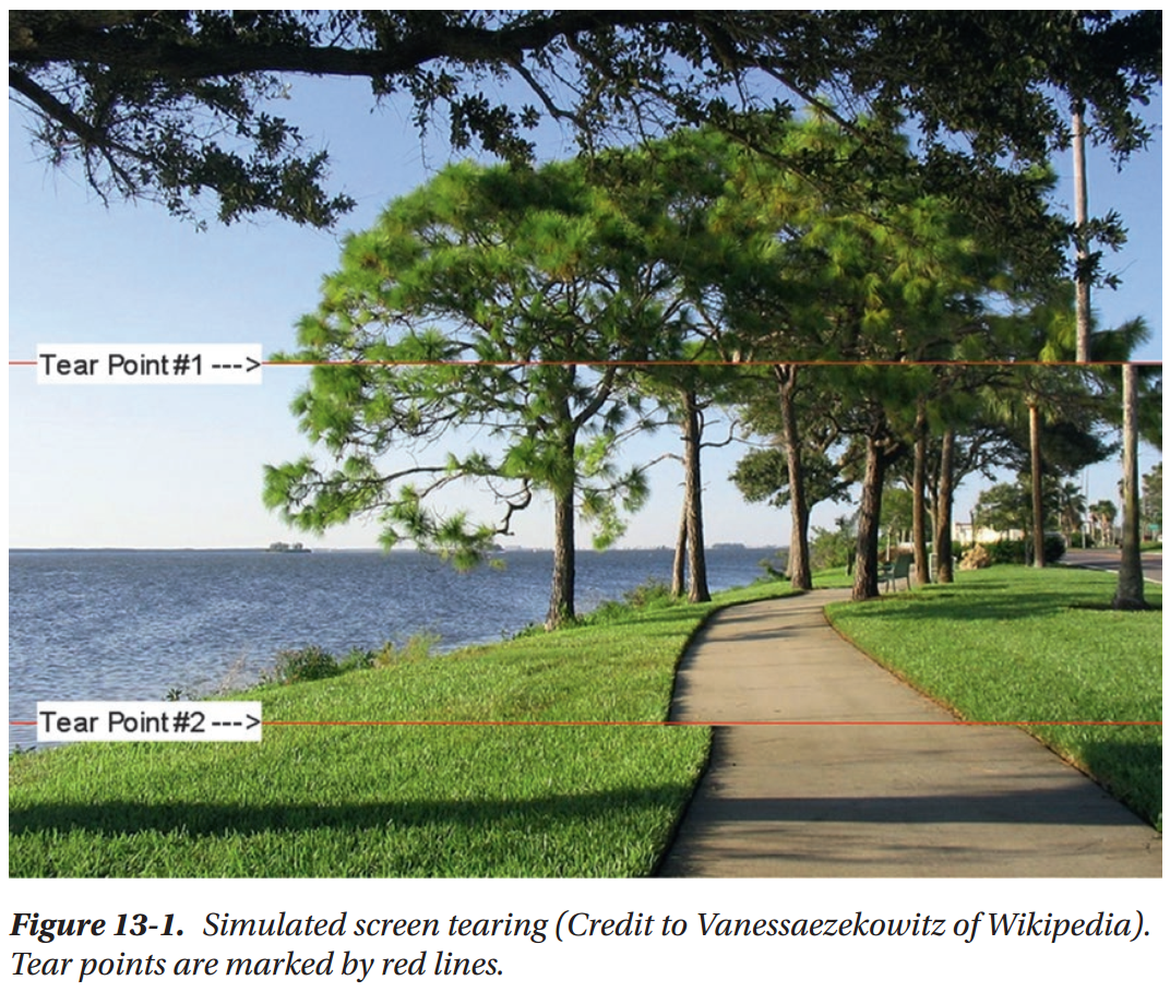
Working Arround VSync
Working Around Your Computer
Practical Profiling
Introducing Nsight Graphics
Are We CPU or GPU bound?
A Handy Shortcut
Tracking Down A Problem Shader
Summary
Chapter 14: Optimizing Shaders
Move Calculations to Vertex Shaders
Avoid Dynamic Branching
Get MAD
Prefer GLSL Functions over Your Own
Use Write Masks
Avoid Unnecessary Overdraw
Final Thoughts
Summary
Chapter 15: Precision
What Is Floating-Point Precision
Case Study: Animation over Time
Working with Lower Precision Variables
Case Study: Point Light Problem
Summary
Chapter 16: Writing Shaders in Unity
Shaders and Materials in Unity
Introducing ShaderLab
A Solid Color Shader
Porting Our Blinn-Phong Shader
Translucent Shaders in Unity
Handing Multiple Lights
Passing Data from C# to Shader Code
Next Steps, ShaderGraph, and the Future
Summary
Chapter 17: Writing Shaders in UE4
Shaders, Materials, and Instances (Oh My!)
Making Things Red
UE4 Material Node Graph Fundamentals
Making a Rim Light Material
The Default Lit Material Inputs
Vertex Shader or Fragment Shader?
Working with Different Shading Models
Blend Modes and Texture Sample Nodes
Passing Data from Code to Materials
How Does All This Relate to Shader Code?
Summary
Chapter 18: Writing Shaders in Godot
Shaders and Materials
The Godot Shading Language
Fragment Shader Output Variables
Making a Custom Rim Light Shader
Custom Vertex Shaders
UV Animation
Translucent Shaders and Blend Modes
Passing Data from Code to Shaders
The Future: Visual Shader Editing?
Summary