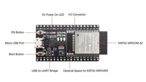
ESP32 芯片是由乐鑫开发的芯片。下图是基于 ESP32 芯片的开发板:

图 1:ESP32 DevKitC V4 开发板
ESP32 的多种应用开发方式
至少有四种方式可以选择:
- 乐鑫官方的 ESP-IDF[1]
- 乐鑫官方的 Arduino 开发工具包[2]
- MicroPython[3]
- TinyGo[4]
TinyGo 目前(2021-03-14)还未支持 ESP32 的 WiFi 和蓝牙
为了方便开发,通常选择 Arduino 开发工具包和 MicroPython。下文选择介绍前者。
Arduino core for the ESP32
官方提供 Arduino 开发工具包是为了使用 Arduino IDE 和 Arduino 的生态,并不是要求一定要再买一块 Arduino 板来连接。
其工具包在 GitHub 上:
要使用这个工具包进行开发,需要做好两个准备:
- 下载和安装 Arduino IDE
- 把 ESP32 开发工具包导入到 Arduino IDE
第一步简单,到官方网站下载即可。以下简要说明第二步。
安装和配置 Arduino IDE 的 ESP32 开发环境
导入方式有三种,根据情况选择。资料比较全,这里简单列举出来,不再过多重复。
-
最简单的配置和安装方式是使用 Arduino IDE 的开发板管理器:
https://github.com/espressif/arduino-esp32/blob/master/docs/arduino-ide/boards_manager.md (Installation instructions using Arduino IDE Boards Manager)
前提是能访问 raw.githubusercontent.com 这个域名(被墙了)。
-
如果没法访问,那就自己用 Git 去 Clone GitHub 仓库:
https://github.com/espressif/arduino-esp32/blob/master/docs/arduino-ide/windows.md (Steps to install Arduino ESP32 support on Windows)
不过这种方式比较慢,因为要 Clone 整个仓库,比较大。
-
下载仓库的压缩文件:
https://www.cnblogs.com/codeit/p/14323836.html (Arduino配置ESP32开发环境)
不过由于不能执行 Git 方式的自动 Clone,需要自行下载 Git 子模块。即文章里已经有提到的 ESP32_AzureIoT_Arduino。这个是开发包的官方依赖,不用担心存在什么大问题,使用其他方式也得这样安装。
如果 GitHub 下载慢,试试 GitLab:
- https://gitlab.com/schaepher/arduino-esp32 (Arduino Esp32)
- https://gitlab.com/schaepher/ESP32_AzureIoT_Arduino (ESP32 AzureIoT Arduino)
选择哪块板
在 Arduino IDE 的 [ 工具 | 开发板 | ESP32 Arduino ] 菜单里面能够看到有多个选项,不同的选项对应着不同的配置。为了不影响后续开发,需要选择合适的板。
如果上面有和手头上相同名称的板,那么直接选择就可以了。如果没有相同名称或者不太确定,那么就需要根据一些内容来判断。
从已有信息中找到目标。
菜单的第一个选项是 ESP32 Dev Module。根据这个名称到工具包代码里搜索,找到 boards.txt 这个文件。里面就是各种板的配置。
大致对比了一下不同板的配置,基本都一样。部分区别列举如下:
- build.variant 选项
这个是跟引脚相关的配置。主要关注这个配置。 - build.flash_freq 选项
这个是 Flash 存储器的频率。默认的值有的是 40m 有的是 80m。 - menu.PSRAM.* 选项
有些板带了 PSRAM,就会多出这部分配置
其他选项在目前阶段看起来不太重要,因此这里主要关注 variant (变体)选项,确保选择的板的引脚对应正确。
以 build.variant=esp32 为例。在 variants 文件夹里面找到 esp32 文件夹,打开里面的 pins_arduino.h。再结合仓库里的 README.md 底下的 PINMAP,就能知道 pins_arduino.h 里面配置的含义了。

图 2:引脚配置文件里的数字与开发板引脚的对应关系
从上图看出,数字不是乱选的。这些数字分别对应了通用输入/输出引脚(GPIO,General Purpose Input Output),其中有一部分引脚只能作为通用输入(GPI)。
不同的开发板可能会在设计的时候就占用了不同的 GPIO 引脚,因此需要在开发板剩余的 GPIO 中选择合适的引脚配置到 pins_arduino.h 里面。
在配置的时候,需要参考开发板的引脚文档。如果缺少文档,可以直接看板上的引脚数字。这些引脚表示对应数字的 GPIO 引脚。具体的 GPIO 引脚都可以用作哪些功能,可以参考芯片的数据手册[5]。
在选择开发板选项的时候,着重注意一下引脚文件的配置就行了。不要选择那种配置了已被开发板元器件占用的引脚。
引脚配置文件里面还有开头的几个宏定义,这些是固定的。例如:
#define NUM_DIGITAL_PINS 40
表示芯片共有 40 个数字管脚。ESP 32 共有 49 个管脚,其中 9 个引脚的类型为 P,即 Power。剩下的要么是通用 I/O ,要么是独用的 I 或者 O。
SPI 通信
变体引脚配置文件里面跟 SPI 相关的引脚使用的是:
- SS = GPIO5
- MOSI = GPIO23
- MISO = GPIO19
- SCK = GPIO18
查询芯片的数据手册可以看到这些引脚的功能。

图 3:ESP32 数据手册里的管脚描述[5]
一个引脚有多个功能,但在使用的时候只选择一种。
ESP32 共有 3 组 SPI(SPI、HSPI、VSPI),这里是用到其中的 VSPI,没啥特别。
拿个例子过一遍开发和上传的流程
在官方的 Arduino 开发工具包里面找到 libraries/ESP32/examples,里面有例子。
在将开发板连接到电脑之后,挑选一个例子的代码复制到 Arduino IDE 的编辑器里面,编译并上传。
例如选择 examples/ChipID/GetChipID/GetChipID.ino 文件里的代码:
uint32_t chipId = 0;

void setup() {
  Serial.begin(115200);
}

void loop() {
  for(int i=0; i<17; i=i+8) {
    chipId |= ((ESP.getEfuseMac() >> (40 - i)) & 0xff) << i;
  }

  Serial.printf("ESP32 Chip model = %s Rev %d
", ESP.getChipModel(), ESP.getChipRevision());
  Serial.printf("This chip has %d cores
", ESP.getChipCores());
  Serial.print("Chip ID: "); Serial.println(chipId);

  delay(3000);

}
然后编译,这个选项在 [ 项目 | 验证/编译 ],或者用快捷键 Ctrl+R。
编译通过后上传,这个选项在 [ 项目 | 上传 ],或者用快捷键 Ctrl+U。
以下是上传的日志:
esptool.py v3.0-dev
Serial port COM7
Connecting.....
Chip is ESP32-D0WDQ6 (revision 1)
Features: WiFi, BT, Dual Core, 240MHz, VRef calibration in efuse, Coding Scheme None
Crystal is 40MHz
MAC: xx:xx:xx:xx:xx:xx
Uploading stub...
Running stub...
Stub running...
Changing baud rate to 921600
Changed.
Configuring flash size...
Auto-detected Flash size: 4MB
Compressed 8192 bytes to 47...
Writing at 0x0000e000... (100 %)
Wrote 8192 bytes (47 compressed) at 0x0000e000 in 0.0 seconds (effective 16383.2 kbit/s)...
Hash of data verified.
Compressed 18656 bytes to 12053...
Writing at 0x00001000... (100 %)
Wrote 18656 bytes (12053 compressed) at 0x00001000 in 0.2 seconds (effective 938.7 kbit/s)...
Hash of data verified.
Compressed 207008 bytes to 108334...
Writing at 0x00010000... (14 %)
Writing at 0x00014000... (28 %)
Writing at 0x00018000... (42 %)
Writing at 0x0001c000... (57 %)
Writing at 0x00020000... (71 %)
Writing at 0x00024000... (85 %)
Writing at 0x00028000... (100 %)
Wrote 207008 bytes (108334 compressed) at 0x00010000 in 2.2 seconds (effective 767.1 kbit/s)...
Hash of data verified.
Compressed 3072 bytes to 128...
Writing at 0x00008000... (100 %)
Wrote 3072 bytes (128 compressed) at 0x00008000 in 0.0 seconds (effective 4915.3 kbit/s)...
Hash of data verified.

Leaving...
Hard resetting via RTS pin...
这样就上传成功了。
接着验证结果。在 [ 工具 | 串口监视器 ] 里面,把波特率设置为 115200,就可以看到输出。例如:
ESP32 Chip model = ESP32-D0WDQ6 Rev 1
This chip has 2 cores
Chip ID: 5940616
接下来就可以发挥创造力了~
参考
[1]: https://docs.espressif.com/projects/esp-idf/zh_CN/stable/esp32/ (ESP-IDF 编程指南)
[2]: https://github.com/espressif/arduino-esp32 (Arduino core for the ESP32)
[3]: http://docs.micropython.org/en/latest/esp32/quickref.html (Quick reference for the ESP32)
[4]: https://tinygo.org/microcontrollers/esp32-coreboard-v2/ (ESP32 - CORE BOARD)
[5]: https://www.espressif.com/sites/default/files/documentation/esp32_datasheet_cn.pdf (ESP32系列芯片——技术规格书)
