背景
产品需要用到这个技术,在wiki找到了这篇文章。
创建者Confluence Wiki Admin
Sep 24, 2018 in Xilinx-wiki
Table of Contents
An Example to describe Golden Image Search
4. Time for Multiboot from QSPI
6. Multiboot and NAND Bad Block Management
| Date | Version | Author | Description of Revisions |
|---|---|---|---|
| 18/02/13 | 0.1 | Prush Palanichamy | Initial revision |
| 15/5/13 | 1.0 | Prush Palanichamy | Added info on FSBL Fallback, and handling NAND Bad blocks during Multiboot |
Summary
This document shows how Multiboot works. We use QSPI as the boot device for this exercise.
Theory
There are three mechanisms to do multiboot.
1) Golden Image Search
This is initiated by BootROM when no valid header is found at the bottom of Flash Memory. The BootROM will start searching for a valid header at every 32KB offset. This mechanism is slow but reliable.
2) BootROM Multiboot
This is initiated by FSBL i.e, user. If the BootROM finds a valid header and hands off to FSBL, then FSBL can load the Multiboot register and issue a soft reset. After a soft reset, BootROM will use the address of the Multiboot register to read the BootROM header. This mechanism is used for example, when user wants to run self-test and diagnostics, and then jump to the actual application.
3) FSBL Fallback
To recover from an error condition, FSBL does a Fallback and enables BootROM to load another bootable image (the golden image that was originally present and in a known good state) if that image is present in the flash memory. FSBL updates a multiboot register and does a soft reset so that BootROM executes and loads the next present, valid image. The FSBL fallback can happen with or without Soft Reset. Refer the Zynq-7000 AP SoC Software Developer’s guide for more information on FSBL Fallback for secure and non-secure boot modes.
http://www.xilinx.com/support/documentation/user_guides/ug821-zynq-7000-swdev.pdf
Golden Image Search and BootROM Multiboot are described in the following figure (TRM version 14.5 - figure 6-3).
Here is an Example to describe Multiboot from FSBL
Hardware Setup
Implementation Details
| Design Type | PS – any revision |
|---|---|
| SW Type | Standalone |
| Boards/Tools | ZC702 |
| Xilinx Tools Version | IDE 14.5 |
| Files Provided | Note |
|---|---|
 Multiboot_Tech_Tip_V2.0.zip Multiboot_Tech_Tip_V2.0.zip |
Under generated_files folder you will see the two image files that we need to create using SDK 1) Hello_World_1.bin 2) Hello_World_2.bin. If you are using these files, you can skip the SDK steps and jump to *Programming to QSPI* section. |
Implementation
We will create two boot files.
- Hello_World_1.bin = (FSBL_1 + Hello_World_1)
- prints “Hello World from Image 1 at address 0x0000_0000” - Hello_World_2.bin = (FSBL_2 + Hello_World_2)
- prints “Hello World from Image 2 at address 0x0004_0000”
Like in the following Figure, FSBL_1 will fallback, FSBL_2 will not.
Hello_World_1 will print “Hello World from Image 1 at address 0x0000_0000”
And Hello_World_2 will print “Hello World from Image 2 at address 0x0004_0000”
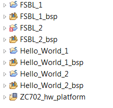
We will program Hello_World_1.bin at offset 0x00 of QSPI address and Hello_World_2.bin at offset 0x40000 (256KB) of QSPI address. We will modify the FSBL_1 to go through a fallback. Our expectation here is that when FSBL_1 goes through a fallback it will eventually find the image at 0x0004_0000 and will execute FSBL_2 and Application2. Just for this example, we will set “FSBL_DEBUG” flag, so we can see the Debug prints from FSBL.
The sequence of events will be as follows
- BootROM executes and loads image 1
- FSBL_1 executes
- FSBL_1 sets MultiBoot Reg address as 0x40000/ 0x8000 = 0x8, eventually
- FSBL_1 issues a soft reset
- BootROM executes and loads image2
- FSBL_2 executes
- hello_world2 application executes and prints “Hello World from Image 2 at address 0x0004_0000”
1. Step by Step Instructions
- Create a FSBL_1 application for zc702 board. Set FSBL_DEBUG flag.
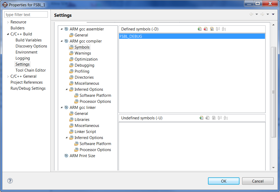
We will modify the main() function in FSBL_1 project to disable Handoff. The change required is highlighted in blue. This function FsblHandoff() is called at the very bottom of main(), by disabling this function we generate a failure condition and will go through an FSBL fallback.
//FsblHandoff(HandoffAddress);
/*
* Should not come over here
*/
OutputStatus(ILLEGAL_RETURN);
FsblFallback();
Summary :
- Build FSBL_1 and generate FSBL_1.elf
- Create a
Hello_World_1 applicationfor zc702 board. Openhelloworld.cfile and change the print instruction to “Hello World from Image 1 at address 0x0000_0000” - Create a
FSBL_2 applicationfor zc702 board. SetFSBL_DEBUGflag. Build FSBL_2 and generate FSBL_2.elf - Create one more
Hello_World_2 applicationfor zc702 board. Openhelloworld.cfile and change the print instruction to “Hello World from Image 2 at address 0x0004_0000” - Open “Xilinx Tools->Create Zynq Boot Image” from SDK. And choose the FSBL_1.elf and Hello_World_1.elf to create Hello_World_1.bin
- Open “Xilinx Tools->Create Zynq Boot Image” from SDK. And choose the FSBL_2.elf and Hello_World_2.elf to create Hello_World_2.bin
Programming QSPI
- Copy BOOT.bin from from Zynq releases http://wiki.xilinx.com/zynq-releases (you can use the latest release, 14.5 release is used for testing this Techtip) in to a SD card and boot the ZC702 board in SD mode. Make sure you have connected the USB UART port of ZC702 board using a USB cable to your PC.
NOTE: You can also use XMD to run u-boot. The commands for running u-boot.elf from XMD is
XMD% connect arm hw
XMD% source ps7_init.tcl
XMD% ps7_init
XMD% dow u-boot.elf
XMD% con
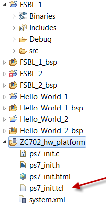
u-boot.elf is available at http://wiki.xilinx.com/zynq-releases and you can find ps7_init.tcl in the folder “ZC702_hw_platform”
- Open a terminal to the USB-UART of the board (any one of Hyperterminal, teraterm, Putty) at 115200 baud rate. You should see “zynq-uboot>” prompt
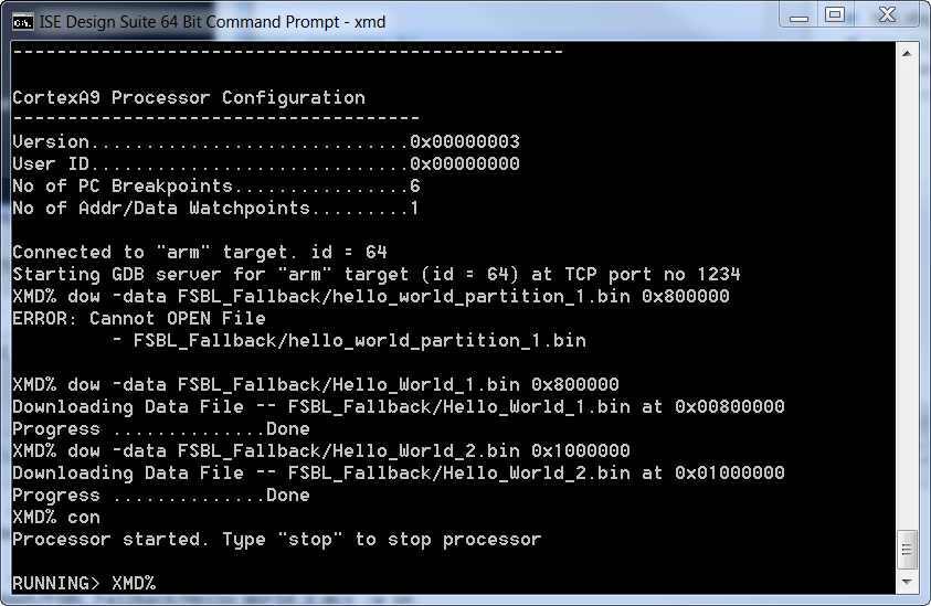
- Open an XMD window (from command prompt or SDK) and cd to where the Hello_World_1.bin and Hello_World_2.bin exists
On XMD prompt – run the following commands
XMD% connect arm hw
XMD% dow -data Hello_World_1.bin 0x800000
XMD% dow -data Hello_World_2.bin 0x1000000
XMD% con
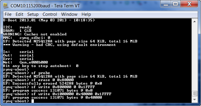
Now, on the zynq-uboot> prompt on terminal, run the following commands
zynq-uboot> sf probe
erase 512 KB
zynq-uboot> sf erase 0 0x80000
program data at 0x80_0000 to QSPI offset 0x00
zynq-uboot> sf write 0x800000 0 0x1FFFF
program data at 0x100_0000 to QSPI at 0x40000 (256 KB)
zynq-uboot> sf write 0x1000000 0x40000 0x1FFFF//
2. Verification of Multiboot
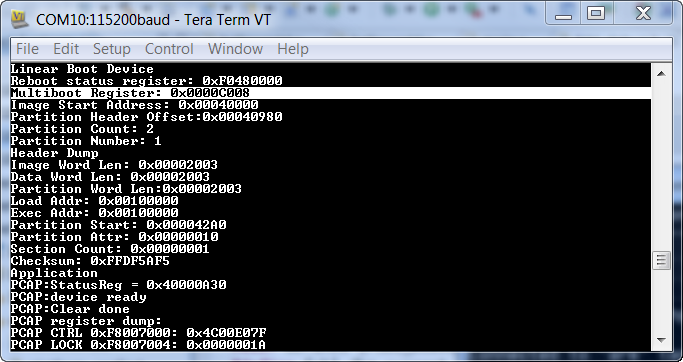
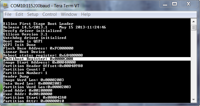
Boot the board in QSPI mode. Check for the print on serial terminal. You will see that FSBL 1 failed and the Multiboot Register eventually incremented to 8 i.e, 8 * 0x8000 = 0x40_0000.
“Multiboot Register: 0x0000C008”
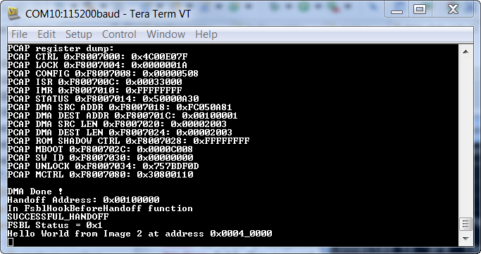
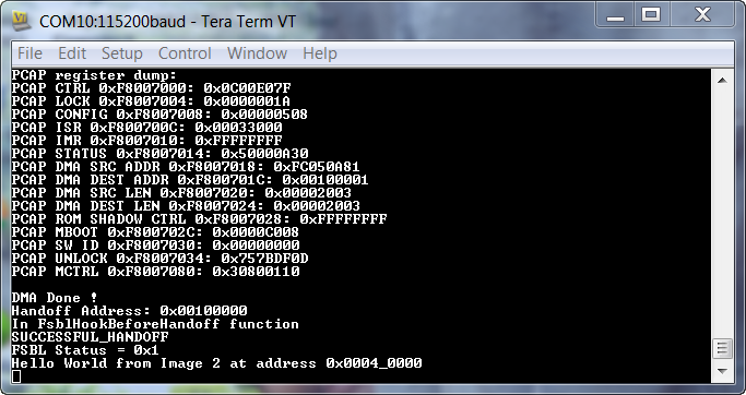
After FSBL_2 executed, it gave control to Hello_World_2 which printed “Hello World from Image 2 at address 0x0004_0000.
An Example to describe Golden Image Search
Now we will erase the first sector and check if we can still from image2. In this case the sequence of events will be as follows
-
BootROM executes – and couldn’t find a valid header at bottom of flash
-
BootROM goes for hunting a valid header at every 32KB offset
-
BootROM sets MultiBoot Reg address as 0x40000/ 0x8000 = 0x8, eventually
-
Finds a valid header at 0x0004_0000
-
FSBL_2 executes and hands off to hello_world2 application which prints “Hello World from Image 2 at address 0x0004_0000”
Erasing Image1 of QSPI
- Copy BOOT.bin from from Zynq releases http://wiki.xilinx.com/zynq-releases in to a SD card and boot the ZC702 board in SD mode
- Open Hyperterminal at 115200 baud rate. You should see “zynq-uboot>” prompt
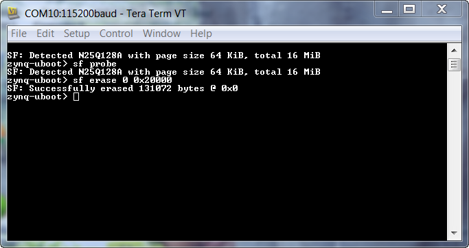
On the zynq-uboot prompt on terminal, run the following commands
zynq-uboot> sf probe
erase 128 KB
zynq-uboot> sf erase 0 0x20000//
3. Verification of Multiboot
Boot the board in QSPI mode. Check for the print on serial terminal. You will see that FSBL 1 never executed and the Multiboot Register eventually incremented to 8 by BootROM i.e, 8 * 0x8000 = 0x40_0000.
“Multiboot Register: 0x0000C008”
FSBL Debug Prints:
Application Prints:
4. Time for Multiboot from QSPI
Let’s erase the second image and program it at the top of Flash, offset at 0x00FE_0000. We will measure the approximate time taken for the first message to appear on screen.
Erasing Image1 of QSPI
- Copy BOOT.bin from from Zynq releases http://wiki.xilinx.com/zynq-releases in to a SD card and boot the ZC702 board in SD mode
- Open Hyperterminal at 115200 baud rate. You should see “zynq-uboot>” prompt
On XMD prompt – run the following commands
XMD% connect arm hw
XMD% dow -data Hello_World_2.bin 0x1000000
XMD% con
On the zynq-uboot prompt on terminal, run the following commands
zynq-uboot> sf probe
erase 512 KB
zynq-uboot> sf erase 0xFE0000 0x20000
program data at 0x100_0000 to QSPI at 0x00FE_0000
zynq-uboot> sf write 0x1000000 0xFE0000 0x1FFFF
When you boot in QSPI mode, you will see the Multiboot register is 0x1FC. If you use a scope to see when the UART line toggles, you can determine the boot time.
Boot time when image is at bottom of flash : 200 msec (measured from power on to toggling of DS12 LED on ZC702 board)
5. Locking the Boot Sector
Note: Protect command is currently not supported in u-boot
In the above example, we were able to simply erase the first 128KB of the QSPI device after booting from SD mode. We don’t want this in production. In this example we will find out how to lock the boot image such that an “sf erase” command will not be able to erase the boot area.
//protect 256KB to 512KB
protect on 0x40000 0x80000
sf read 0x800000 0x40000 0x400
md 0x800000 0x100

sf erase 0x40000 0x40000
sf read 0x800000 0x40000 0x400
md 0x800000 0x100
6. Multiboot and NAND Bad Block Management
QSPI devices don’t have bad blocks, but NAND devices may have Bad blocks. Consider the scenario depicted in figure below. The BootROM header contains the address of the multiboot image which is Sector 6. While making the image using Bootgen or while programming the device using u-boot the bad blocks are not accounted for, but BootROM accounts for them when reading from the Flash device. Due to the difference in how BootROM and u-boot handle bad blocks, there is an issue with successfully running BootROM multiboot or FSBL fallback on NAND devices.
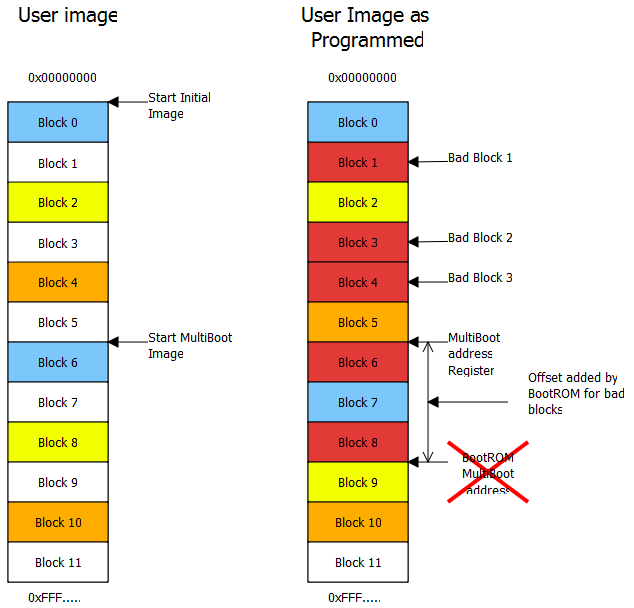
The solution to this issue is for FSBL or the application to find the number of bad blocks address from user’s multiboot address. For example if you have want to have a second Image at offset 0x0100_0000 of NAND and there are three bad sectors each of size 128KB. You have to load the Multiboot address register with a value of 0x0100_0000 - (3 * 128 KB) i.e, 0x0100_0000 – 0x0060_0000 = 0x00A0_0000
This is not an issue for Golden Image Search mechanism as the BootROM will search for a valid header at every sector of the NAND device.