The ARM Cortex-M3 (CM3) architecture is a 32-bit microcontroller core designed to replace many 8-bit and 16-bit devices by offering faster speeds and advanced system features.
Leveraging these advanced features requires a sound understanding of the CM3 hardware as well as dedicated systems software development.
This article explains the CM3 hardware used for pre-emptive context switching as well as how to develop systems software routines that enable multi-tasking programs.
Understanding the CM3 Hardware
The CM3 has dedicated multi-tasking hardware including task-switching interrupts (SysTick and PendSV) and two stack pointers.
The SysTick hardware consists of a 24-bit timer that triggers an interrupt each time it counts to zero.
The PendSV interrupt is a software request, which can manually force a context switch.
Essentially, the SysTick interrupt enables round-robin style scheduling while the PendSV supports FIFO style.
The stack pointers for the CM3 include the main stack pointer (MSP) and the process stack pointer (PSP).
The MSP is always used when in handler mode (when an interrupt is being serviced) and can optionally be used during regular program execution.
The PSP is limited to use during regular program execution.
This gives the system designer several options.
The ARM Cortex-M3 technical reference manual suggests one configuration:
“For a basic protected thread model, the user threads run in Thread mode using the process stack, and the kernel and the interrupts run privileged using the main stack.”
Alternatively, the MSP can be used exclusively for handling interrupts (privileged) while the PSP executes all other execution threads (unprivileged).
To create a pre-emptive, multitasking system with the CM3 hardware, the systems designer must design a task table as well as routines for:
initializing the switching system, creating new tasks, and handling the context switching interrupts.
An entry in the task table can be as simple as the task stack pointer and a set of flags telling the context switcher which tasks to execute.
Typedef struct {

      Void * stack; //Task’s stack pointer

      Uint32_t flags; //In Use flag and dynamic execution flag

} task_table_t;
This implementation uses two flags.
One flag indicates if an entry is “in use” while the other is a dynamic execution flag.
The “in use” flag is helpful when creating tasks to indicate which table entries are available.
The dynamic execution flag allows the context switcher to quickly decide whether or not to execute any given task.
If memory is sparse, a NULL stack pointer can be the “in use” flag, and the LSb of the stack pointer can act as the dynamic execution flag
(since the stack is word-aligned the bottom two LSb’s are not used). Doing this requires additional overhead when switching to ensure the bottom two LSb’s are masked properly.
A detailed understanding of the CM3 stacking hardware and register convention is imperative to implementing multi-tasking handling routines.
Figure 1 below shows the different values assigned to the PSP when switching tasks.
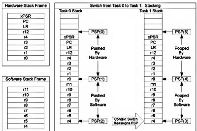
Figure 1: Values assigned to the PSP when switching tasks
When an interrupt request is serviced on the CM3, some registers (see “Hardware Stack Frame” in Figure 1)
are automatically pushed by hardware onto the current stack—in this case, the process stack.
Software must save the remaining general-purpose registers (see “Software Stack Frame”).
The following describes the chronological values assigned to the PSP when performing a context switch (reference Figure 1):
* PSP(0): Just before an interrupt request is serviced
* PSP(1): Just after an interrupt request is serviced
* PSP(2): After the context switcher saves the necessary registers on the stack
* PSP(3): After the context switcher reassigns the PSP to a new execution thread
* PSP(4): After the context switcher loads the last know state of the new thread
* PSP(5): After the interrupt request returns and execution of the new thread begins/resumes
Designing Context Switching Routines
Using the above details about the CM3 stacking and registers, the systems designer needs to create just three routines:
the context switcher, the system initializer, and the task creator.
Figure 2 below shows a software flow diagram of each routine.
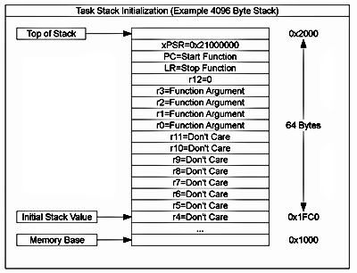
Figure 2. Software flow diagram of system routines
The context switcher is invoked only through the SysTick and PendSV interrupt requests.
It immediately pushes the software stack frame on to the process stack.
It then saves the current value of the PSP in the task table of the previously executing task.
Next, it decides which task to execute. This implementation--designed for fast switching--traverses the task table starting
with the previously executing task and switches to the next task having the “execute” flag set.
The context switcher can alternatively be as sophisticated or as simple as the systems designer wishes and may consider task priority, CPU time, or other factors
when designing a switching algorithm. Once the next task is determined, the PSP is assigned the value of the new task’s stack pointer retrieved from the task table.
Lastly—immediately before returning from the interrupt—the software pops the software stack frame from the process stack.
When the interrupt returns, the CM3 interrupt handling hardware pops the hardware stack frame and execution of the new task begins/resumes.
In Figure 2, points “A” and “B” mark the locations where additional functionality may be added to the context switcher.
An example of which is task timers. A single hardware timer can be used to track the CPU time utilized by each task. To do this, an entry in the task table for the task time is added.
At point “A”, the task timer for the previously executing task is saved in the task table. At point “B”, the task timer for the upcoming task is loaded from the task table.
The systems designer may also consider setting the privilege level for the new task or adding task specific memory protection.
The CM3 hardware supports both of these advanced features.
The system initializer shown in Figure 2 initializes the first task’s stack as well as the switching related hardware:
namely the SysTick and PendSV interrupts. Figure 3 below shows the values of an initialized task stack--allocated dynamically or statically.
The hardware stack frame must be populated correctly in order for the task to start and stop properly.
The values of the software stack frame are ignored.
Nonetheless, the initial value of the stack pointer must point to the bottom of the software stack frame in order for
the context switcher to load the software stack frame when switching to the task.
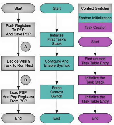
Figure 3. Values of an initialized task stack
Once the task’s stack is ready, the SysTick and PendSV interrupts are initialized.
The SysTick reload register is loaded with the desired value to set the round robin interrupt time.
The interrupt interval is calculated by multiplying the CPU frequency by the reload value.
Once the SysTick timing is configured, the interrupt is enabled to start switching.
The PendSV interrupt is enabled by default, and no initialization is required.
The PendSV interrupt is used to force a context switch after all initialization is complete.
After which, execution never returns to the task initialization function.
The initial task can create additional tasks using the task creator routine (See Figure 3 above).
Creating an additional task involves preparing the task’s stack and configuring an entry in the task table.
The task creator routine finds an unused entry in the task table, populates the entry, and initializes the stack.
If there are no unused entries in the task table, no more tasks can be created unless the systems designer integrates a mechanism to dynamically resize the task table.
If an available entry is found, the task creator routine initializes the stack for the new task.
The calling function provides the memory location and size of the stack.
This allows the caller to dynamically or statically allocate the stack.
The task switching routines can then be implemented in systems with or without a dynamic memory allocator.
The stack initialization of a new task uses the same approach as initializing the initial task.
The hardware stack frame must be properly initialized while the software stack frame is allocated but can be left uninitialized.
For POSIX style threads, the type for new thread routines is:
void * routine(void * args);
Using this template, args is assigned to r0 in the hardware stack (additional arguments, if desired, are assigned to r1, r2, and r3
according to the “Procedure Call Standard for the ARM Architecture ABI” revision r2.08), routine is assigned to the start function,
and a systems designer defined routine defines the stop function.
The stop function erases the task table entry so that the context switcher no longer executes the task—both the “in use”
and dynamic execution flags should be cleared. The stop function can also be provided by the caller allowing the developer
to free the stack or do any other task cleanup that might be required.
The result of routine() is passed to the stop function in r0 using the following prototype for the stop function:
void stop_function(void * ret);
The stop function can then be used to pass the return value to any functions having requested this data.
Under POSIX, the return value of routine() is required for implementing the pthread_join() function.
Conclusion
The CM3 has many advanced features that lend themselves to creating an embedded operating system.
These features are context-switching friendly and include two stacks designed for switching system integration as well as two interrupts
which enable support for round robin and FIFO switching algorithms.
The systems developer must have a sound understanding of the CM3 switching hardware
as well as the stacking and register conventions in order to create the three routines required for context switching:
the context switcher, system initialization, and the task creator
Context Switching on the Cortex-M3
https://coactionos.com/projects/coactionos/wiki/Context_Switching_on_the_ARM_Cortex_M3
The ARM Cortex-M3 architecture is designed with special features to facilitate implementing a pre-emptive RTOS.
The system code takes advantage of these features when implementing context switching code.
ARM Cortex-M3 Context Switching Hardware
Interrupts
The SysTick and PendSV interrupts can both be used for context switching.
The SysTick peripheral is a 24-bit timer that interrupts the processor each time it counts down to zero.
This makes it well-suited to round-robin style context switching. The PendSV interrupt allows a task to cede control of the CPU when it is inactive
(such as when sleeping or waiting for a hardware resource) which is helpful for FIFO style context switching.
In addition to these interrupts, the ARM Cortex-M3 also includes two stack pointers.
Stacks
The stack pointers for the ARM Cortex-M3 include the main stack pointer (MSP) and the process stack pointer (PSP).
The MSP is always used when handling interrupts and optionally used during regular program execution.
The PSP is only used during regular program execution.
ARM recommends using the MSP for the kernel as well as interrupts and recommends the PSP for executing other tasks.
While the architecture provides the interrupts and the stack pointers, the implementation must provide the context switching code.
Context Switching Software Implementation
The RTOS manages the interrupts and stacks in order to achieve context switching.
When switching contexts, the RTOS needs a way to keep track of which tasks are doing what using a task or scheduler table.
Three routines are then required to: perform the context switch, initialize the system, and create new tasks.
Task Table
The task table, at a minimum, saves each task's stack pointer; it is also helpful to save other information,
such as the task parent and status, to allow the context switcher to selectively execute tasks.
The following code shows an example of a structure that can be used for an entry in the task table:
typedef struct {
     void * sp; //The task's current stack pointer
     int flags; //Status flags includes activity status, parent task, etc
} task_table_t;
int current_task;
task_table_t task_table[MAX_TASKS];
The sp member stores the value of the task's stack pointer, while flags holds the task status. In this example, the task uses two status bits: one to indicate that the table entry is in use and the other to specify whether or not to execute the task.
Context Switching Routine
The context switcher needs to:
- save the state of the current task,
- update the current task index to the next task to be executed,
- set up the CPU to either use the MSP (if it's time to run the kernel) or the PSP,
- and finally load the context of the task which is about to execute.
The following code is an example of a context switcher, preceded by some helper functions, and the interrupt handlers.
static uint32_t * stack; //This is stored on the heap rather than the stack

#define MAIN_RETURN 0xFFFFFFF9  //Tells the handler to return using the MSP
#define THREAD_RETURN 0xFFFFFFFD //Tells the handler to return using the PSP

//Reads the main stack pointer
static inline void * rd_stack_ptr(void){
  void * result=NULL;
  asm volatile ("MRS %0, msp
	"
      //"MOV r0, %0
	"
      : "=r" (result) );
  return result;
}

//This saves the context on the PSP, the Cortex-M3 pushes the other registers using hardware
static inline void save_context(void){
  uint32_t scratch;
  asm volatile ("MRS %0, psp
	"
      "STMDB %0!, {r4-r11}
	"
      "MSR psp, %0
	"  : "=r" (scratch) );
}

//This loads the context from the PSP, the Cortex-M3 loads the other registers using hardware
static inline void load_context(void){
  uint32_t scratch;
  asm volatile ("MRS %0, psp
	"
      "LDMFD %0!, {r4-r11}
	"
      "MSR psp, %0
	"  : "=r" (scratch) );
}

//The SysTick interrupt handler -- this grabs the main stack value then calls the context switcher
void systick_handler(void){
    save_context();  //The context is immediately saved
    stack = (uint32_t *)rd_stack_ptr();
    if ( SysTick->CTRL & (1<16) ){ //Indicates timer counted to zero
        context_switcher();
    }
    load_context(); //Since the PSP has been updated, this loads the last state of the new task
}

//This does the same thing as the SysTick handler -- it is just triggered in a different way
void pendsv_handler(void){
    save_context();  //The context is immediately saved
    stack = (uint32_t *)rd_stack_ptr();
    core_proc_context_switcher();
    load_context(); //Since the PSP has been updated, this loads the last state of the new task
}

//This reads the PSP so that it can be stored in the task table
static inline void * rd_thread_stack_ptr(void){
    void * result=NULL;
    asm volatile ("MRS %0, psp
	" : "=r" (result) );
    return(result);
}

//This writes the PSP so that the task table stack pointer can be used again
static inline void wr_thread_stack_ptr(void * ptr){
    asm volatile ("MSR psp, %0
	" : : "r" (ptr) );
}
This is the function for the actual context switcher.
This context switcher uses the MSP for task 0 (assumed to be the kernel) and the PSP for other tasks.
It is also possible to use the PSP for the kernel and just use the MSP during interrupt handling.
//This is the context switcher
void context_switcher(void){
   task_table[current_task].sp = rd_proc_stack_ptr(); //Save the current task's stack pointer
   do {
      current_task++;
      if ( current_task == MAX_TASKS ){
         current_task = 0;
         *((uint32_t*)stack) = MAIN_RETURN; //Return to main process using main stack
         break;
      } else if ( task_table[current_task].flags & EXEC_FLAG ){ //Check exec flag
         //change to unprivileged mode
         *((uint32_t*)stack) = THREAD_RETURN; //Use the thread stack upon handler return
         break;
      }
   } while(1);
   wr_proc_stack_ptr( task_table[current_task].sp ); //write the value of the PSP to the new task
}
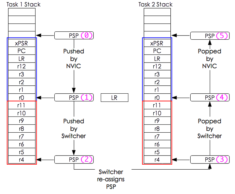
The following diagram shows the chronology of the stack pointer when a switch happens between task one and task two.
Note that because this implementation uses the MSP for task zero, the mechanics of a context switch are slightly different when switching to and from task zero.
A context switching implementation can just as easily use the PSP for all tasks and the MSP for interrupts by using THREAD_RETURN rather than MAIN_RETURN above.
Initialization
The first thing that must be done is to initialize the main stack's task table entry.
//This defines the stack frame that is saved  by the hardware
typedef struct {
  uint32_t r0;
  uint32_t r1;
  uint32_t r2;
  uint32_t r3;
  uint32_t r12;
  uint32_t lr;
  uint32_t pc;
  uint32_t psr;
} hw_stack_frame_t;

//This defines the stack frame that must be saved by the software
typedef struct {
  uint32_t r4;
  uint32_t r5;
  uint32_t r6;
  uint32_t r7;
  uint32_t r8;
  uint32_t r9;
  uint32_t r10;
  uint32_t r11;
} sw_stack_frame_t;

static char m_stack[sizeof(sw_stack_frame_t)];

void task_init(void){
     ...
     task_table[0].sp = m_stack + sizeof(sw_stack_frame_t);
     ....
    //The systick needs to be configured to the desired round-robin time
    //..when the systick interrupt fires, context switching will begin
}
Creating a New Task
Once the context switcher is initialized, there needs to be a mechanism to start new tasks.
Starting a new task involves finding an available entry in the task table and initializing the new task's stack.
int new_task(void *(*p)(void*), void * arg, void * stackaddr, int stack_size){
    int i, j;
    void * mem;
    uint32_t * argp;
    void * pc;
    hw_stack_frame_t * process_frame;
    //Disable context switching to support multi-threaded calls to this function
    systick_disable_irq();
    for(i=1; i < MAX_TASKS; i++){
        if( core_proc_table[i].flags == 0 ){
            process_frame = (hw_stack_frame_t *)(stackaddr - sizeof(hw_stack_frame_t));
            process_frame->r0 = (uint32_t)arg;
            process_frame->r1 = 0;
            process_frame->r2 = 0;
            process_frame->r3 = 0;
            process_frame->r12 = 0;
            process_frame->pc = ((uint32_t)p);
            process_frame->lr = (uint32_t)del_process;
            process_frame->psr = 0x21000000; //default PSR value
            core_proc_table[i].flags = IN_USE_FLAG | EXEC_FLAG;
            core_proc_table[i].sp = mem +
                stack_size -
                sizeof(hw_stack_frame_t) -
                sizeof(sw_stack_frame_t);
            break;
        }
    }
    systick_enable_irq();  //Enable context switching
    if ( i == MAX_TASKS ){
        //New task could not be created
        return 0;
    } else {
        //New task ID is i
        return i;
    }
}

//This is called when the task returns
void del_process(void){
  task_table[current_task_index].flags = 0; //clear the in use and exec flags
  SCB->ICSR |= (1<<28); //switch the context
  while(1); //once the context changes, the program will no longer return to this thread
}
Conclusion
ARM, with the Cortex M architecture, delivers valuable hardware resources to enable context switching.
The interrupts support both round robing and FIFO style scheduling while the dual stacks allow the kernel process and interrupts to execute on a dedicated stack.
With just a few software routines to perform the context switching, initialize the system, and create new stacks, system developers can create a functioning pre-emptive kernel.
For more information on context switching on the Cortex-M3, see the Cortex-M3 technical reference manual from ARM.