https://www.kickstarter.com/projects/1708444109/rfidler-a-software-defined-rfid-reader-writer-emul
https://github.com/ApertureLabsLtd/RFIDler
http://adamsblog.aperturelabs.com/2013/08/rfidler-open-source-software-defined.html
The Goal
To produce a tool for Low Frequency (125-134Khz) RFID research projects, as well as a cut-down (Lite) version that can be embedded into your own hardware projects. The fully featured version we hope to bring in for around £30.00, and the Lite version for under £20.00.
Features
We have written extensive firmware which includes a user interface and an API to allow easy use of the system and to allow you to explore, read and emulate a wide range of low frequency RFID tags.
- Utilise ANY modulation scheme, including bi-directional protocols
- Write data to tag
- Read data from tag
- Emulate tag
- Sniff conversations between external reader & tag
- Provide raw as well as decoded data
- Built-in antenna
- External antenna connection
- USB power and user interface
- TTL interface
- GPIO interface
- JTAG interface for programming
- USB Bootloader for easy firmware updating
- External CLOCK interface if not using processor
- External power connector if not using USB
The hardware gives you the capability to read/write/emulate more or less any LF tag, but we've also taken the hard work out of most of them by implementing all the tag types we can find in the public domain. These include:
- EM4102 / Unique
- Hitag 1/2/S
- FDX-B (ISO 11784/5 Animal Standard)
- Q5
- T55xx
- Indala
- Noralsy
- HID Prox
- NXP PCF7931
- Texas Instruments
- VeriChip
- FlexPass
RFIDler——软件RFID阅读器/读卡器/模拟器
http://adamsblog.aperturelabs.com/2013/08/rfidler-open-source-software-defined.html
I've said it before and I'll say it again: I don't understand how it works.
Not only that, but I don't want to understand, and I don't need to understand!
Well, that's not quite true - I need to understand enough to know which bits I don't need to understand, but then that's it! Stop! Enough already!!!
RFID is, as with a lot of these technologies, mysterious by nature.
It relies on strange physical phenomena like "induction" and "electro-magnetism" and "near-fields", etc.
Yes, what we Code Monkeys like to call "Magic Moonbeams".
It's all very nasty and analoguey. I don't like it. Give me the nice binary digital, please!
So in my never ending quest to find tools that convert the scary analogue world into a nice friendly digital one, RFID is clearly a prime candidate.
There are lots of RFID/NFC devices out there these days, and you've probably got one or two in your pocket right now -
whether it's your car keys, alarm fob, door entry card, credit card, etc.
Of course, there are endless varieties of RFID readers to access them with,
but what I'd like is something that reads them all, and meets my standard criteria: small and cheap.
To be fair, there are plenty of readers out there that seem to meet this criteria.
You can buy a simple RFID USB reader for as little as 10-15 quid, but you'll find that it's of limited use as
it will almost certainly be dedicated to one 'standard', and you'd therefore need dozens of them to be able to read 'everything'.
There are also tools like the Proxmark3 that are truly universal and can read pretty much anything, but, unfortunately, these are not cheap.
However, it is certainly worth looking at the PM3 as it really is quite an amazing bit of kit -
often described as the 'Swiss Army Knife of RFID', it is versatile enough to read pretty much any tag in the standard LF/HF frequency ranges,
so will at least be useful in giving us an idea as to what we're up against... We'll be using it later to look at some specific examples.
So, going right to the beginning, what does an RFID tag actually do?
Well, it depends. There are basically two functions, and the rest is 'details':
Firstly, pretty much every RFID tag will IDENTIFY itself. That is function one.
Secondly, some tags will store DATA. That is function two.
The 'details' revolve around how it does those two things - is it blindly spitting out an ID and/or DATA, or is there some security or other command structure built around it?
That's the simple view, and if you want the longer, more detailed explanation, there are entire volumes written about it.
The 'details' can run into hundreds of pages, so I'm not going to even start.
My goal, here, is to talk about the low level fundamental communications that seperate the evil analogue underworld from the lovely, friendly digital fairy garden, where we all like to play.
And it all begins with our friend "induction".
At the very low level, RFID/NFC relies on the fact that if you energise a coil and place another coil near it, the second coil will pick up some of that energy through induction.
Moreover, the two coils become magically (or magnetically, depending which world you come from) 'coupled',
so it's possible for the second coil to effect the voltage on the first, and it does this by shorting itself out.
If it does so, there will be a drop in the voltage on the first coil, and this is called "DAMPING".
That's it. In a nutshell, that's how RFID works:
the coils 'talk' to each-other by either sending energy (from the READER), or causing an energy drop (from the TAG).
In a little more detail, what happens is this (and for the purpose of this section, we'll assume the TAG is the dumbest type that just spits out an ID):
the READER energises its coil by powering it on and off repeatedly.
For a standard LF system, this will be 125,000 times per second, or 125KHz.
This is known as the 'CARRIER'.
The TAG, when placed in this field, will scavenge some power from its now inductively-coupled coil and come to life.
If the reader needs to send an extra 'wake up' (or any other) command, it can do so by simply switching it's CARRIER off altogether for short periods.
The TAG stores enough energy that it can keep running for long enough to interpret these gap periods, even though it's temporarily lost its power source.
The length of the CARRIER signal between the gaps will usually signify a 0 or a 1, so like this the READER can send binary messages.
In other words, they're talking 'ASK': Amplitude Shift Keying.
Data is sent by shifting the amplitude of the signal.
More accurately, they're talking 'OOK': On Off Keying.
A message going from the READER to the TAG is signalled by the CARRIER being ON or OFF
and the message coming back is either DAMPED or UN-DAMPED.
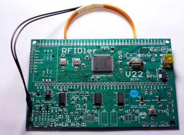
Things get a lot easier to understand if we visualise them, so here is a plain 125KHz CARRIER viewed from an oscilloscope:
And here is the READER sending a message to the TAG:
In this case it's using a long pulse to represent a '1' and a short a '0', so the message here is '11000', or 'START_AUTH' if you're a HITAG2.
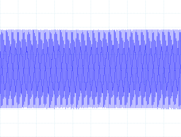
As I mentioned, the TAG can also send messages back to the READER by shorting it's own coil and DAMPING the READER's coil.
The result looks something like this:
It looks quite similar to when the READER sends a message, but you'll note that
it can't reduce the CARRIER all the way down to nothing - instead it's either a 'DAMPED' or 'UN-DAMPED' wave.
This is because it's not directly controlling the voltage on the READER's coil, only affecting it through induction.
However, it is clearly still perfectly readable.
In this case, if we take the damping action as a '1' and non-damped as a '0',
we get '1010101010010110011010', which is, in fact, a MANCHESTER encoded bitstream.
So what has MANCHESTER got to do with anything?
Well, this is where it starts to get interesting - if you look in details at the specs for these kind of tags,
you'll find that they mention modulation schemes such as 'Manchester', 'Bi-Phase', 'FSK', 'PSK', 'NRZI', 'ASK'...
WTF? We've already established that the two devices can only do ASK,
so where does all this FSK/PSK/Manchester malarky come from???
This is where I think a lot of the confusion lies.
Once you start trying to do something other than what a particular manufacturer intended with an RFID tag,
you quickly get lost in a mire of conflicting modulation schemes and other irrelevancies.
This particularly applies to the readers as well - if I want to find a reader that gives me access to the raw data, just forget it.
Most readers want to go that little bit further and fully de-modulate the signal for me.
And to do that, they need to know exactly how the signal was modulated in the first place...
And to know that, they need to know which standard tag type they're going to read, and so on, and so on...
It's easy to see how we've ended up with this situation.
A lot of these devices were built back in the days when computing power didn't come cheap,
so the designers tried to do as much as possible in the analogue world before handing over to the digital at the last moment.
This meant building circuitry that not only handled the low-level ASK communication, but also the secondary modulation schemes that were layered on top.
The RF world have been going through a revolution, moving to SDR, in which they're doing the same thing -
handling only the very low level analogue stuff in circuitry and doing the rest in software on small powerful microcomputers, and it's time we did the same for RFID!
So when I asked our tame (well, nearly... he's mostly house-trained and has at least stopped biting the postman)
Chip Monkey to build me an RFID reader that only gave me the lowest level data, he was somewhat surprised to be unable to find an existing reference circuit that exactly fit the bill.
We both thought it would be simple, but no - every circuit was tied to a further demodulation scheme - FSK, PSK, Bi-Phase, etc., and some of them were horrendous!
They look more like they're designed to take you to the moon, rather than read a few bits from a wibbly coil!
For example, here is Microchip's 200 page document with separate example circuits for ASK, PSK and FSK.
http://ww1.microchip.com/downloads/en/devicedoc/51115f.pdf
However, after a bit more searching, we found a 'simple' design:
'The World's Simplest RFID Reader'. http://forums.parallax.com/showthread.php/105889-World-s-simplest-RFID-reader
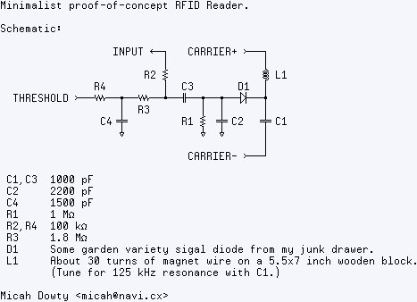
All capacitances are in picofarads. C1 and C3 should be 1000 pF, not 1000 nF. Likewise, C2 is 2200 pF.
Yep.. just a propeller and a few passive components.
To understand this circuit, it's helpful to know how RFID works first.
Here's the 10-second RFID primer for those who aren't already familiar with it:
RFID tags work via magnetic fields, like a transformer.
A coil in the reader generates a magnetic carrier wave, which is picked up by a coil in the tag or card.
This carrier wave powers the card, and provides it with a clock reference.
To send data, the card varies the amount of current it draws from the reader's field, attenuating the carrier wave slightly.
This attenuation is usually used to send some kind of modulated signal.
The card I've been testing with uses a 125 kHz carrier wave, and FSK (Frequency Shift Keyed) modulation.
Zeroes and ones are attenuation waveforms with different frequencies.
So, step one: generating a carrier wave with the propeller.
I use a counter, naturally, and I generate a differential-drive signal on two pins.
This gives me 125 kHz at about 6.6V peak-to-peak.
I use an LC tank tuned near 125 kHz to amplify this and shape it into a sine wave.
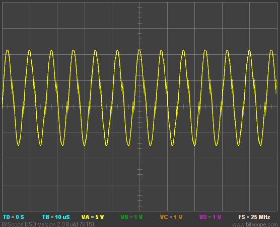
Here's my carrier wave, measured at the junction between L1 and C1.
Note the scale- it's about 20 volts peak-to-peak! (Also notice that my tuning isn't quite perfect. Sadness and despair!)
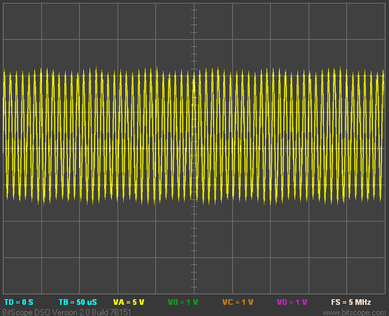
When you bring a proximity card near the reader coil, you can see the attenuation waveform overlaying the carrier wave.
This is at the same voltage scale, measured at the same point, but I zoomed out on the X axis so you can see the pattern clearly:
To detect this signal, I use D1, C2, and R1 as a peak detector and low-pass filter, to remove the majority of the high-voltage carrier wave.
This is then AC coupled via C3.
At this point, the left side of C3 has a "floating" low-voltage waveform that I can position anywhere I want, by changing the bias on C3.
To generate this bias voltage, I use CTRB in DUTY mode.
I'll explain why I call this pin "threshold" later.
R4 and C4 are a low-pass filter give me an analog output voltage from CTRB.
This signal is usually DC- it's used for calibration.
R3 "pulls" the floating waveform toward the analog value output by CTRB.
Now I take advantage of the Propeller's Vdd/2 input threshold, and use the "input" pin as a comparator.
(R2 is just to limit high-frequency noise.)
Now I can use the CTRB voltage to adjust the detection threshold- how much attenuation causes "input" to read 0 vs 1.
Now I have a digital signal, but it's still really noisy.
I use an assembly-language cog to reject as much noise as possible, and time the resulting FSK pulses.
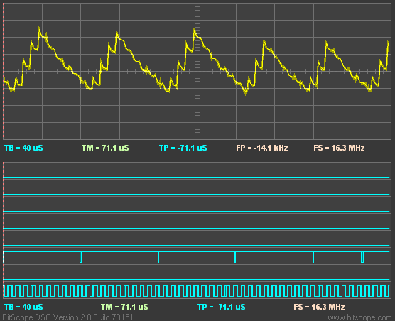
This image shows the analog signal at the junction between R2 and C3, along with the digital pulse detector's output.
The amount of time between pulses signifies a "1" or "0" bit.
In this case, the detection threshold is at 9 carrier wave cycles. Less than 9, it's a 0. More than 9, it's a 1 bit.
End result: I can display the 512 bits of data from my corporate proximity badge. Neat.
I'd include more details on the actual data I've captured and the protocol,
but so far I've only been able to test this with a couple ID badges from the office and I'd rather not share those bits ;)
I have a Parallax RFID starter kit on order, so I'll let you know if I can read any of those tags successfully.
Source code is attached, but be warned it's hugely messy.
Minimalist proof-of-concept RFID Reader. Schematic: INPUT ─┐ CARRIER+ ──┐ │ │ R2 L1 R4 │ C3 D1 │ THRESHOLD ────┳────┻────┳──┳────┫ │ R3 │ │ │ C4 R1 C2 C1 │ │ CARRIER- ──┘ C1,C3 1000 nF C2 2200 nF C4 1500 pF R1 1 MΩ R2,R4 100 kΩ R3 1.8 MΩ D1 Some garden variety sigal diode from my junk drawer. L1 About 30 turns of magnet wire on a 5.5x7 inch wooden block. (Tune for 125 kHz resonance with C1.) Micah Dowty <micah@navi.cx> --- XXX: This is really messy. It doesn't do automatic threshold control, nor does it report back useful information like the length of the card's packet, or the presense/absence of a card. You may have to fidget with the value of init_frqb to adjust the threshold bias manually. Watch the debug2 output with an oscilloscope. It should be normally high, with series of quick pulses on every FSK attenuation cycle. Tested with HID proximity cards. Seems to be a 16-bit all-ones header, followed by 16*32=512 bits of data. } CON _clkmode = xtal1 + pll16x _xinfreq = 5_000_000 CARRIER_HZ = 125_000 CARRIER_NEG_PIN = 7 ' Carrier wave pin, to capacitor THRESHOLD_PIN = 6 ' PWM output for detection threshold INPUT_PIN = 5 ' Input signal CARRIER_POS_PIN = 1 ' Carrier wave pin, to coil DEBUG_PIN = 0 ' For the 'scope DEBUG2_PIN = 2 OBJ text : "TV_Text" VAR long debug long buffer[128] long capture1[16] long capture2[16] PUB main | i text.start(12) text.str(string("Minimalist RFID reader", 13, "Micah Dowty <micah@navi.cx>", 13)) start repeat longmove(@capture1, @buffer, 16) waitcnt(clkfreq/4 + cnt) longmove(@capture2, @buffer, 16) ' Only display if we get two identical samples, to cut out noise. if isMatch and capture2[0] display buffer[0]~ waitcnt(clkfreq/2 + cnt) PRI isMatch : r | i repeat i from 0 to 15 if capture1[i] <> capture2[i] r := FALSE return r := TRUE PRI display | i text.out(13) repeat i from 0 to 15 text.hex(capture1[i], 8) text.out(" ") text.out(13) PUB start init_frqa := fraction(CARRIER_HZ, clkfreq) debounce := clkfreq / (CARRIER_HZ / 4) bit_threshold := clkfreq / (CARRIER_HZ / 9) cognew(@entry, @debug) PRI fraction(a, b) : f a <<= 1 repeat 32 f <<= 1 if a => b a -= b f++ a <<= 1 DAT org entry mov dira, init_dira mov ctra, init_ctra ' CTRA generates the carrier wave mov frqa, init_frqa mov ctrb, init_ctrb ' CTRB generates a pulse threshold bias mov frqb, init_frqb packet_loop mov buf_offset, #0 mov num_ones, #0 word_loop mov bit_count, #32 ' Measure the time between falling edges, ignoring short gaps. bit_loop or outa, #1 ' XXX: Debug high :edge_wait mov prev_edge, this_edge waitpeq input_mask, input_mask ' Wait for another pulse edge... or outa, #4 ' XXX: Debug2 high waitpne input_mask, input_mask mov this_edge, cnt andn outa, #4 ' XXX: Debug2 low mov r0, this_edge ' How long was that? sub r0, prev_edge cmp r0, debounce wc if_c jmp #:edge_wait ' Too short. Look for another edge. andn outa, #1 ' XXX: Debug low ' Now the difference between first_edge and this_edge ' is the period of the FSK modulated signal that the RFID ' tag is generating. Compare the signal's period against our ' bit threshold, to recover bits. mov r0, this_edge sub r0, first_edge cmp r0, bit_threshold wc if_c add num_ones, #1 if_nc mov num_ones, #0 rcl shift_reg, #1 ' If we've received a long run of ones, sync to the beginning of the packet. cmp num_ones, #16 wz if_z jmp #packet_loop mov first_edge, this_edge ' Start a new bit djnz bit_count, #bit_loop ' If we finished a word, write it to hub memory. add buf_offset, #4 and buf_offset, #$7F mov r0, par add r0, buf_offset wrlong shift_reg, r0 jmp #word_loop init_dira long (|< CARRIER_POS_PIN) | (|< CARRIER_NEG_PIN) | (|< THRESHOLD_PIN) | (|< DEBUG_PIN) | (|< DEBUG2_PIN) init_frqa long 0 init_ctra long (%00101 << 26) | (CARRIER_POS_PIN << 9) | CARRIER_NEG_PIN init_ctrb long (%00110 << 26) | THRESHOLD_PIN input_mask long |< INPUT_PIN init_frqb long $7E000000 ' Default threshold adj_gain long $0 ' Automatic threshold adjustment gain debounce long 0 bit_threshold long 0 first_edge long 0 prev_edge long 0 this_edge long 0 buf_offset long 0 bit_count long 0 num_ones long 0 shift_reg long 0 r0 res 1 fit
The pins in the schematic can be any Propeller pin.
In my setup, I used P1 for CARRIER+, P5 for INPUT, P6 for THRESHOLD, and P7 for CARRIER-.
I did find that you really don't want the INPUT pin to be directly adjacent to either of the CARRIER pins,
since they add a lot of electrical noise.

This led to an 'improved' version, although it's still described as a 'DIY FSK RFID Reader',
http://playground.arduino.cc/Main/DIYRFIDReader
The circuit diagram above was derived from the "World's Simplest RFID Reader" design posted by Micah Dowty.
Based on the Parallax Propeller, Micah's approach was to use passive components only, without amplification, in order to achieve the ultimate in simplicity.
The lack of amplification, however, results in a weak signal, potentially less than 2V PTP.
This signal is then biased by an analog level produced by the Propeller, to try to maintain the signal's DC level near the discrimination point of the Propeller's binary-digital input circuitry.
His code attempts to dynamically calculate that optimal midpoint level, and feed it into the circuit using a filtered PWM DAC output.
Since the signal is weak, it can be distorted by interference and noise, which results in reduced reliability.
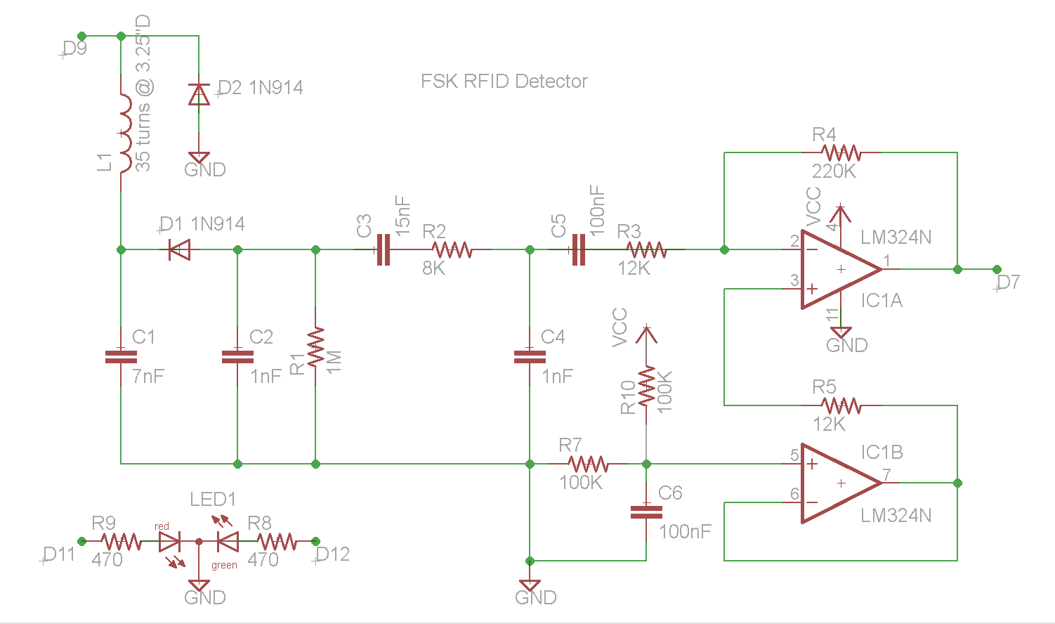
The circuit presented here includes (as Micah suggests in his documentation) one active component: a common low-cost LM234quad-opamp IC (or equivalent).
This addition provides several significant advantages, at a negligible cost.
First, the signal is amplified (using one of the four opamps on the IC package) to a more noise-immune level (of 2-3 volts PTP).
Second, the DC level of the signal is maintained at exactly Vcc/2 using another opamp on the IC, which eliminates the need for the DC propping code in the Arduino.
Third, having the signal amplifier in place allows another low-pass RC filter stage (another capacitor and resistor), which makes the final discriminated digital signal cleaner and more reliable.
The end result is a more robust detected signal with improved noise immunity.
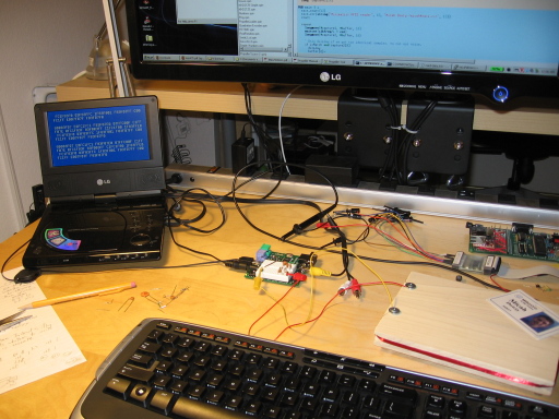
As a quick review of the circuit, the loop is made of a toroidally-wound #22-30 magnet wire (we used an empty roll of Scotch 3.25" I.D. packing tape as former),
and can be remoted from the circuit if needed, via coaxial cable.
The inductor L1 and capacitance C1 should be matched to resonate at around 125 kHz.
When driven at its resonant frequency by the Arduino's 0-5 volt square wave signal, the center point of the resonator (which connects to D1's cathode) will have a fairly pure voltage sine wave,
of about 30V PTP.
When coupled to an RFID tag, the pure sine wave RF will fluctuate visibly as the tag opens and closes its own loop antenna to repeatedly transmit its code.
This modulation is then detected from the RF envelope by D1, C2 and R1, which produce a negative bias voltage with the small detected coded signal, e.g. about 11 RF cycles per coded cycle.
The coded cycles are of two different wave lengths (or frequencies), which represent streams of logic ones and zeros, and they need to arrive at the Arduino chip as binary levels
which can be timed reasonably accurately so as to reliably tell the difference between the two distinct frequencies.
The relatively large capacitor C3 decouples the negative bias voltage from the signal, and is followed by a low-pass RC filter stage (R2 and C4)
which attenuates some of the residual RF spikes from the lower frequency coded RFID signal.
Capacitor C5 decouples the resulting signal and presents it to the amplification stage, implemented by the LM324opamp, IC1.
The latter amplifies the weak signal from about .15V to about 3V PTP (depending of the ratio of R4 to R3), and places it on top of a Vcc/2 bias voltage, about 2.5V in the arduino's case.
This signal is then fed into one of the digital input ports on the Arduino (which also includes some helpful hysteresis),
and is discriminated by the internal comparator into a square wave of ones and zeroes.
so possibly still not quite what we're looking for.
But hang on a minute, surely it doesn't matter what type of tag they were using it to read. We've established that the low level communication is ALWAYS using ASK, so the final demodulation of FSK/PSK/Manchester/Whatever is going to be handled by the microprocessor, so we should be able to use this circuit to do any type of tag, not just FSK.
So this brings us back to the question of these 'extra' modulation schemes. Where do they come from, and how do we deal with them?
Let's use the PM3 to take a look at the raw data we get from each type of tag... The PM3 will act as a basic reader circuit and filter out the CARRIER, leaving only the effect of the DAMPING.
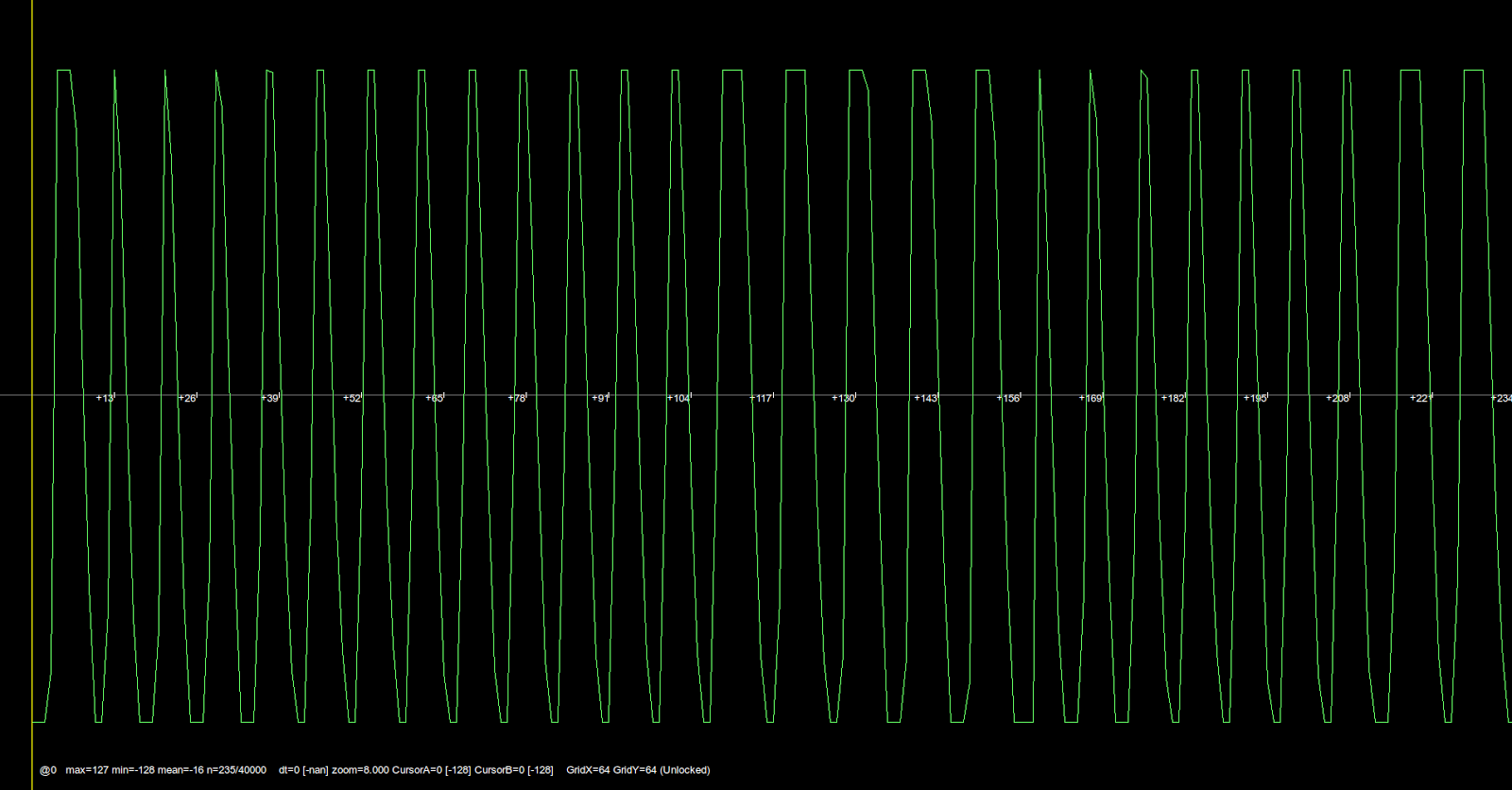
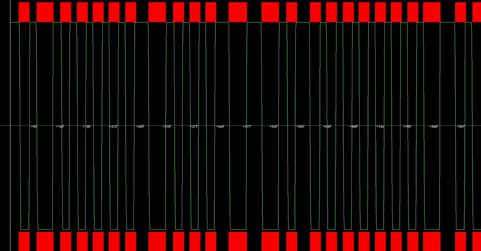
This is an ASK modulated tag:
Exactly what we would expect - a straightforward square wave created by the CARRIER either being DAMPED or UN-DAMPED.
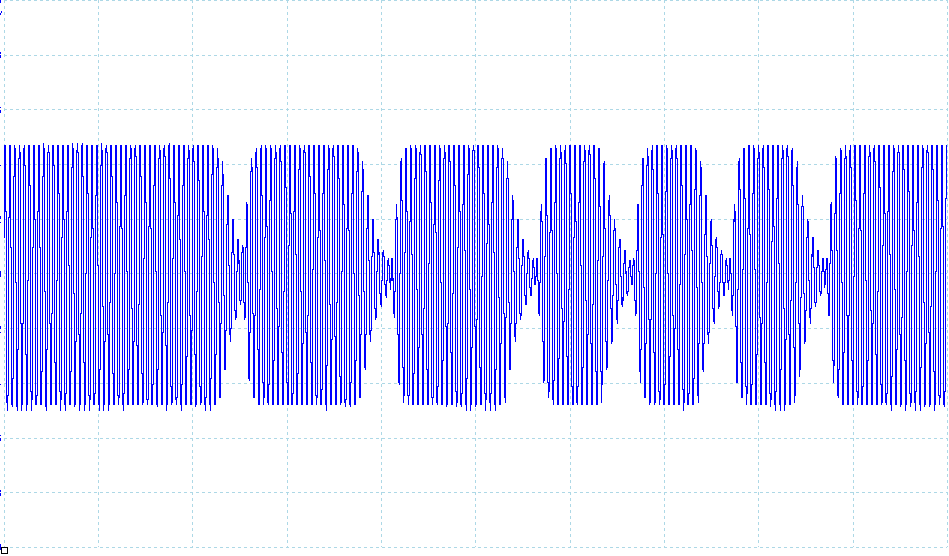
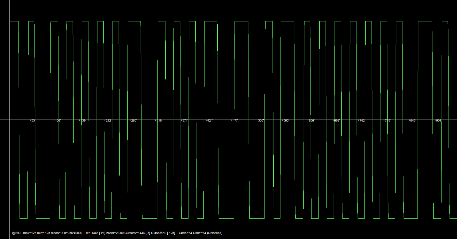
Here is an FSK tag:
Note the two different pulse types - thin ones and fat ones, so we really are seeing different frequency pulses. Weird!
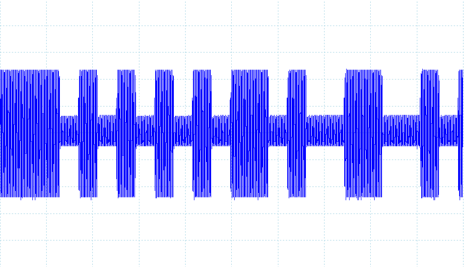
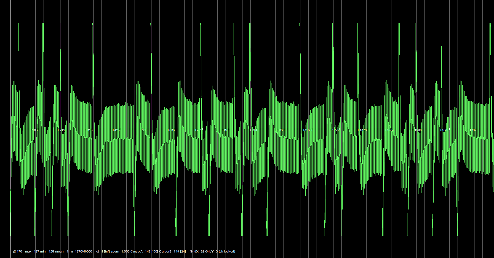
And the strangest yet, PSK:
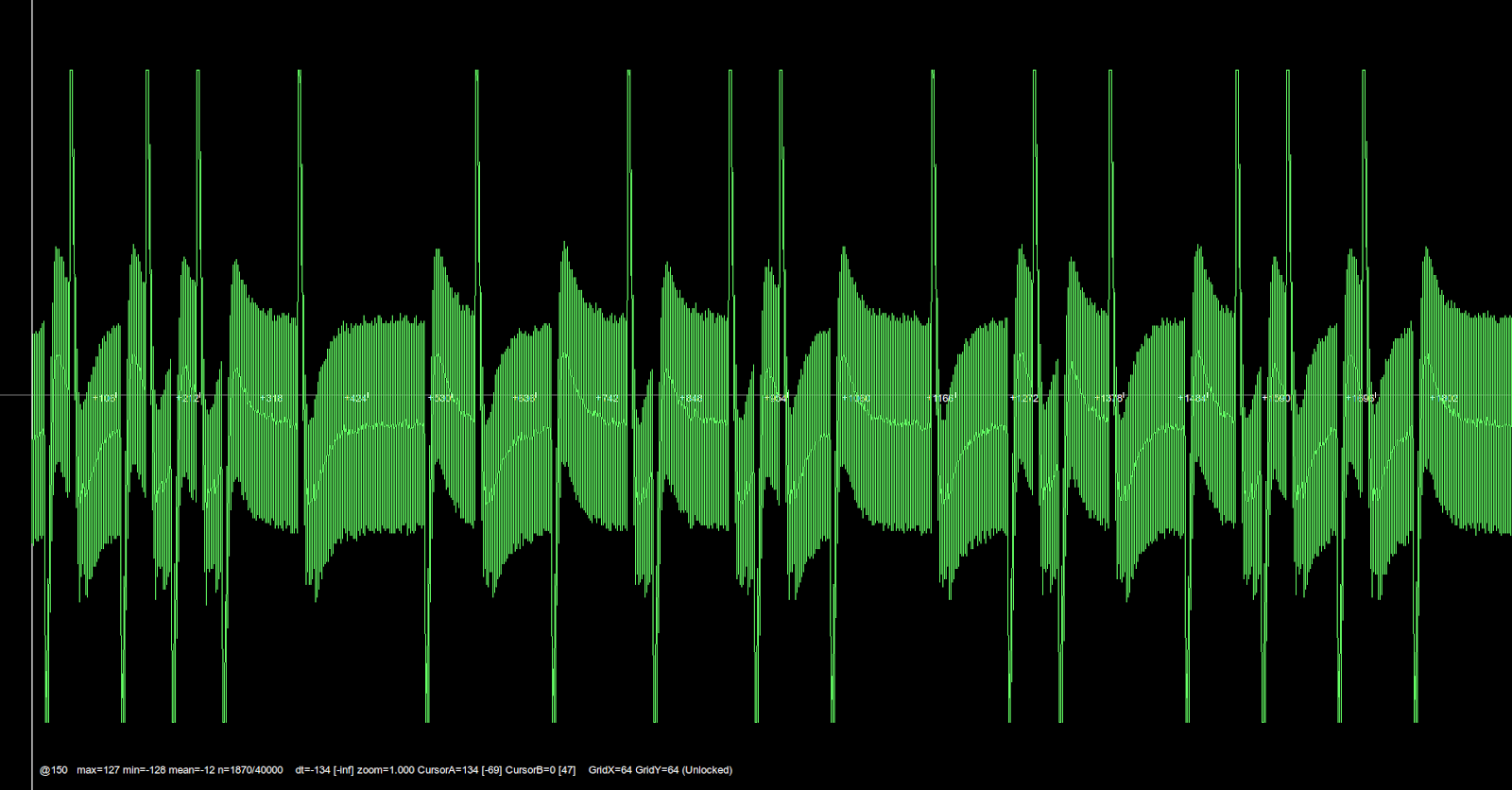
Now that's just crazy. What the hell is that all about?
First, it helps to understand exactly what we're looking at. The green line is showing us the voltage on the READER coil, after the tag has done it's DAMPING (or not). We don't really care what the scale is, just that the bottom of the screen is 0 volts or fully DAMPED and the top of the screen is *some* volts or UN-DAMPED. The circuit that produces this is effectively looking for the presence of a 125KHz CARRIER and raising or lowering the output line accordingly. How it works is irrelevant. I just don't care. That is Chip Monkey's problem! :)
So now I know what the lines mean, the question is how they get to look like they do. The first one is simple: ASK/OOK modulation is either ON or OFF, so we get a line at the top of the screen when we're UN-DAMPED and a line at the bottom when we're DAMPED.
If we think of what the tag's doing as creating a mask which either lets the CARRIER through or not, this makes perfect sense. Here I've marked the image with a red blob whenever the tag is DAMPING its coil:
So far, so obvious. Let's look at the FSK signal in the same way:
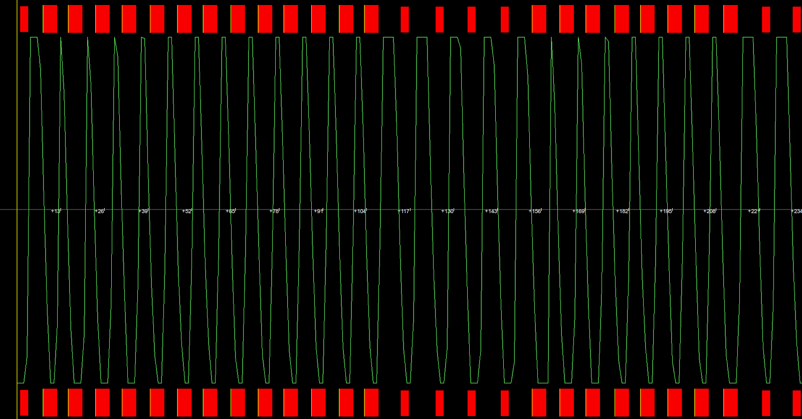
So now, instead of signalling data directly by DAMPING for a 0 or a 1, we are creating a whole new CARRIER by DAMPING for different periods and allowing short or long pulses of the original CARRIER through. The fully DAMPED signal doesn't mean anything, it's the width and number of pulses of the UN-DAMPED signal that carries the information. In this case, 5 fat spikes means '0' and 7 thin spikes means '1' (or 12 thin spikes means '11'), so we've got '011010'. Neat!
OK, so what about the crazy PSK guy?
Well, this is interesting because what's actually happening here is that the coil is being DAMPED relative to the frequency of the original CARRIER itself. In this case, it's going at exactly half the speed, so it's effectively blocking half the CARRIER pulses, and most of the time producing a signal that isn't quite strong enough to reach the top of the screen, and doesn't have time to reach the bottom either, which gives us the chunky bits in the middle. However, whenever there is a phase change, the resulting half-bit repetition means that the DAMPING or UN-DAMPING now lasts for a full clock cycle of the original CARRIER, so we get a little burst of HIGH or LOW popping through, hence the spikes. In this images I've marked the mask in pink for where we're DAMPING 50% of the time, and the phase shifts are red or black as normal.
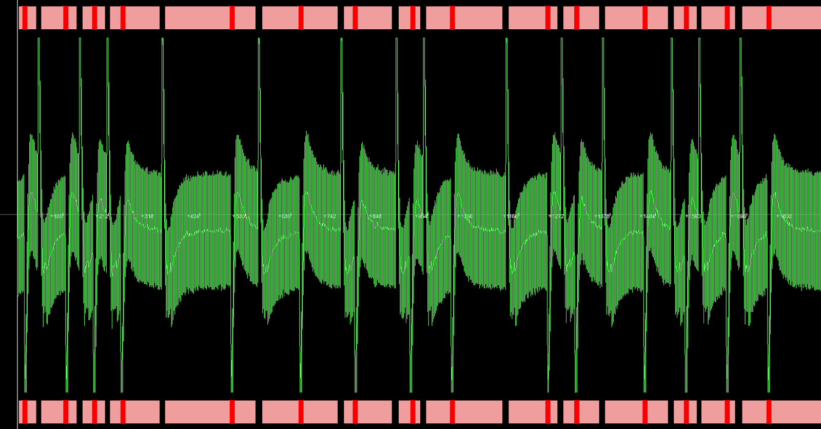
We can see that the fully DAMPED sections line up with the LOW spikes and the UN-DAMPED with the HIGH. It's harder to read these by eye, but basically whenever there is a phase change (i.e. a spike in either direction), the bit value changes. If there is no phase change, the bit value stays the same. The number of bits depends on how long the gap is between the spikes, so if one was to overlay a grid and you knew how long a bit period was, you could simply count off the periods between bit changes and you've got your bitstream.
If we assume we're starting with a 0, this decodes as: '01101010001111100111000100010110000111010011100101101100001'. Easy-peasy! :)
Great, so now we understand what's going on, let's see if the circuit we've found will do the job...
As it turned out, the answer was 'not quite' for two reasons:
1. It couldn't handle the 'down' spikes of PSK.
2. As soon as we started playing with it, we were hit with a flurry of feature-creep! Yes, we wanted it to do more...
For a start, why have only a reader when you could also have a writer? Unlike some technologies, there is really no difference in the RFID world between a reader and a writer. As long as the reader can send signals to the tag, it can send 'write' and 'data' commands, just as easily as reading the tag's emissions. Well, almost as easily - it just needs to be able to switch off it's coil as well as modulating it. Clearly that's not an issue.
And why have only a writer when you could have an emulator? Again, the only fundamental difference between a TAG and a READER/WRITER is that one energises it's coil and the other grounds it. Everything else works pretty much the same, so given the right hardware, we have the perfect platform for a Software Defined device...
So Chip Monkey built us one. And it was good. In fact, it was so good that we decided that instead of just publishing the schematics and blogging about it, we would try and give it life and free it into the world...
Accordingly, RFIDler was born, and is now live on Kickstarter:
http://www.kickstarter.com/projects/1708444109/rfidler-a-software-defined-rfid-reader-writer-emul
The full details and some videos of the prototype in action are be on the project page, but in short the aim is to produce a tool for LF RFID research, for under £30.00, and a cut-down version that be embedded into your own hardware projects for under £20.00.
I have started a firmware project based around the PIC32, which runs on the aforementioned UBW32 BitWhacker, to get the ball rolling, and will add ports to other platforms as we (or you) test them...
The firmware will live here:
https://github.com/ApertureLabsLtd/RFIDler
If you'd like to have one of these to play with, please go and sign up!