在我们的开发工程中经常会使用到各种图,所谓的图就是由节点和节点之间的连接所形成的系统,数学上专门有一个分支叫图论(Graph Theroy)。利用图我们可以做很多工具,比如思维导图,流程图,状态机,组织架构图,等等。今天我要做的是用开源的HTML5工具来快速构造一个做图的工具。
工具选择
预先善其事,必先利其器。第一件事是选择一件合适的工具,开源时代,程序员还是很幸福的,选择很多。
-
flowchart.js http://adrai.github.io/flowchart.js/ , 基于SVG创建Flow Chart
-
go.js http://www.gojs.net/latest/index.html go.js 提供一整套的JS工具 ,支持各种交互式图表的创建。有免费版和收费版
-
joint.js http://www.jointjs.com/ joint.js 是另一个创建图标库的工具,也提供免费版和商业版
-
jsPlumb http://www.jsplumb.org/ jsPlumb是一套开源的流程图创建工具 ,小巧精悍,使用简单
-
d3 http://d3js.org 在html5领域,d3可谓是最好的可视化基础库,提供方面的DOM操作,非常强大。
最终,我选择了jsPlumb,因为它完全开源,使用很简单,用D3的话可能会多花很多功夫。joint.js也不错。大家可以根据自己的需要选择。
构建静态应用
下面我们一步一步的来使用jsPlumb来创建我们的流程图工具。
第一步是等待DOM和jsPlumb初始化完毕,类似document.ready()和jquery.ready(), 要使用jsPlumb, 需要把代码放在这个函数里:
|
1
2
3
|
jsPlumb.ready(function() { // ... your code goes here ...} |
创建一个jsPlumb的实例,并初始化jsPlumb的配置参数:
|
1
2
3
4
5
6
7
8
9
10
11
12
13
|
//Initialize JsPlumbvar color = "#E8C870";var instance = jsPlumb.getInstance({ // notice the 'curviness' argument to this Bezier curve. the curves on this page are far smoother // than the curves on the first demo, which use the default curviness value. Connector : [ "Bezier", { curviness:50 } ], DragOptions : { cursor: "pointer", zIndex:2000 }, PaintStyle : { strokeStyle:color, lineWidth:2 }, EndpointStyle : { radius:5, fillStyle:color }, HoverPaintStyle : {strokeStyle:"#7073EB" }, EndpointHoverStyle : {fillStyle:"#7073EB" }, Container:"container-id" }); |
这里给给出了一些配置包括,连接线(这里配置了一个贝塞尔曲线),线的风格,连接点得风格。Container需要配置一个对应的DIV容器的id。(这里也可以使用setContainer的方法)
下面我们要创建一个节点(node),每一个节点可以用一个DIV来实现。我这里提供了一个函数来创建节点。
|
1
2
3
4
5
6
7
8
9
10
11
|
function addNode(parentId, nodeId, nodeLable, position) { var panel = d3.select("#" + parentId); panel.append('div').style('width','120px').style('height','50px') .style('position','absolute') .style('top',position.y).style('left',position.x) .style('border','2px #9DFFCA solid').attr('align','center') .attr('id',nodeId).classed('node',true) .text(nodeLable); return jsPlumb.getSelector('#' + nodeId)[0];} |
这里做的事情就是创建了一个DIV元素,并放在对应的容器的制定位置上,注意为了支持拖拽的功能,必须使用position:absolute 。
我使用D3来操作DOM,大家可能会更习惯JQuery,这纯属个人喜好的问题。
最后返回创建节点的实例引用,这是的selector使用了jsPlumb.getSelector()方法,它和JQuery的selector是一样的,这样用的好处是你可以使用不同的DOM操作库,例如Vanilla
下面我使用一个函数来创建端点/锚点(anchor),锚点就是节点上的连接点,用于连接不同的节点。
|
1
2
3
4
5
6
7
8
9
10
11
12
13
14
15
16
17
18
19
20
21
22
23
24
25
26
27
28
29
30
31
32
33
|
function addPorts(instance, node, ports, type) { //Assume horizental layout var number_of_ports = ports.length; var i = 0; var height = $(node).height(); //Note, jquery does not include border for height var y_offset = 1 / ( number_of_ports + 1); var y = 0; for ( ; i < number_of_ports; i++ ) { var anchor = [0,0,0,0]; var paintStyle = { radius:5, fillStyle:'#FF8891' }; var isSource = false, isTarget = false; if ( type === 'output' ) { anchor[0] = 1; paintStyle.fillStyle = '#D4FFD6'; isSource = true; } else { isTarget =true; } anchor[1] = y + y_offset; y = anchor[1]; instance.addEndpoint(node, { uuid:node.getAttribute("id") + "-" + ports[i], paintStyle: paintStyle, anchor:anchor, maxConnections:-1, isSource:isSource, isTarget:isTarget }); }} |
instance是jsPlumb的实例
node是我们用addNode方法创建的Node实例
ports,是一个string的数组,指定端点的个数和名字
type,可能是output或者input,指定端点的种类,一个节点的输出端口可以连接另一个节点的输入端口。
这里anchor是一个四维数组,0维和1维分别是锚点在节点x轴和y轴的偏移百分比。我这里希望把端口画在节点的左右两侧,并按照端口的数量均匀分布。
最后使用instance.addEndpoint来创建端点。注意这里只要指定isSource和isTarget就可以用drag&drop的方式来连接端点,非常方便。
下面一步我们提供一个函数来连接端点:
|
1
2
3
4
5
6
7
8
9
10
11
12
13
14
15
|
function connectPorts(instance, node1, port1, node2 , port2) { // declare some common values: var color = "gray"; var arrowCommon = { foldback:0.8, fillStyle:color, 5 }, // use three-arg spec to create two different arrows with the common values: overlays = [ [ "Arrow", { location:0.8 }, arrowCommon ], [ "Arrow", { location:0.2, direction:-1 }, arrowCommon ] ]; var uuid_source = node1.getAttribute("id") + "-" + port1; var uuid_target = node2.getAttribute("id") + "-" + port2; instance.connect({uuids:[uuid_source, uuid_target]});} |
node1和node2是源节点和目标节点的引用,port1和port2是源端口和目标端口的名字。
使用instance.connect方法来创建连接。 overlays用来添加连接线的箭头效果或者其他风格,我这里没有使用,因为觉得都不是很好看。大家如果要用,只要把overlays加入到instance.connect的方法参数就可以了。
调用以上方法来创建节点,端点和连接线。
|
1
2
3
4
5
6
7
|
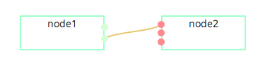
var node1 = addNode('container-id','node1', 'node1', {x:'80px',y:'20px'});var node2 = addNode('container-id','node2', 'node2', {x:'280px',y:'20px'});addPorts(instance, node1, ['out1','out2'],'output');addPorts(instance, node2, ['in','in1','in2'],'input');connectPorts(instance, node1, 'out2', node2, 'in'); |
这里我们创建了两个节点,第一个节点有两个输出端口,第二个节点有三个输入端口,然后把第一个节点的out2端口连接到第二个端点的in端口。效果如下:
最后我们给节点增加drag&drop的功能,这样我们就可以拖动这些节点来改变图的布局了。
|
1
|
instance.draggable($('.node')); |
这里似乎依赖于JQuery-UI,我还不是很清楚。
交互式创建节点
我们已经初步具有了创建图的功能,可是节点的创建必须通过程序,我们希望用交互的方式来创建节点。
通常我们希望有一个tree view的控件,让后通过拖拽来创建对应类型的节点。这里我使用了这个开源的tree view,基于bootstrap https://github.com/jonmiles/bootstrap-treeview
我们先创建一个tree view:
|
1
2
3
4
5
6
7
8
9
10
11
12
13
14
15
16
17
18
19
|
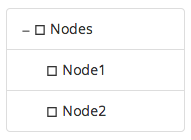
function getTreeData() { var tree = [ { text: "Nodes", nodes: [ { text: "Node1", }, { text: "Node2" } ] } ]; return tree;}//Initialize Control Tree View$('#control-panel').treeview({data: getTreeData()}); |
树上有两个节点:
然后我实现从树上拖拽对应的节点,到流程图上的逻辑。
|
1
2
3
4
5
6
7
8
9
10
11
12
13
14
15
16
17
18
19
20
21
22
23
24
25
26
27
|
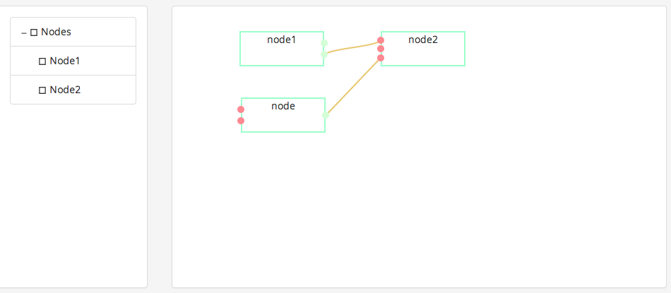
//Handle drag and drop$('.list-group-item').attr('draggable','true').on('dragstart', function(ev){ //ev.dataTransfer.setData("text", ev.target.id); ev.originalEvent.dataTransfer.setData('text',ev.target.textContent); console.log('drag start');});$('#container-id').on('drop', function(ev){ //avoid event conlict for jsPlumb if (ev.target.className.indexOf('_jsPlumb') >= 0 ) { return; } ev.preventDefault(); var mx = '' + ev.originalEvent.offsetX + 'px'; var my = '' + ev.originalEvent.offsetY + 'px'; console.log('on drop : ' + ev.originalEvent.dataTransfer.getData('text')); var uid = new Date().getTime(); var node = addNode('flow-panel','node' + uid, 'node', {x:mx,y:my}); addPorts(instance, node, ['out'],'output'); addPorts(instance, node, ['in1','in2'],'input'); instance.draggable($(node));}).on('dragover', function(ev){ ev.preventDefault(); console.log('on drag over');}); |
这里要注意的是要避免和jsPlumb拖拽端点的逻辑冲突,当检测到target是jsPlumb对象是需要直接从drop方法中退出以执行对应的jsPlumb的drop逻辑。
好了,一个绘制流程图的软件工具初步完工。
我把代码放在oschina的代码托管服务上了, 大家有兴趣可以下来试试 http://git.oschina.net/gangtao/FlowChart-Builder
转至:http://gangtao.is-programmer.com/posts/71082.html