
一、 设计思路如下:
1)一旦检测到按键资源按下(高电平到低电平变换),电平检测模块 就会拉高H2L_Sig电平,然后拉低。
2)10ms延迟模块,检测到H2L_Sig高脉冲,就会触发10ms过滤抖动,然后拉高输出。
3)当按键释放 电平检测模块,会拉高 L2H_Sig电平,然后拉低。
4)10ms延迟模块 检测到L2H_Sig的高脉冲,就会触发10ms过滤抖动,然后拉低输出。
二、电平检测模块以及测试激励代码如下所示:
module detect(
input CLK,
input RSTn,
input Pin_In,
output H2L_Sig,
output L2H_Sig
);
/***********************************************/
//parameter T100US=14'd9999;
parameter T1US=7'd99;//99个时钟周期即99个上升沿,设置1us的延迟是为了测试激烈便于观察仿真波形
/*********************************************************/
reg [6:0]Count1;
reg isEn;
always@(posedge CLK or negedge RSTn)
if(!RSTn)
begin
Count1<=7'd0;
isEn<=1'b0;
end
else if(Count1==T1US)
isEn<=1'b1;
else
Count1<=Count1+1'b1;
/******************************************************/
reg H2L_F1,H2L_F2,L2H_F1,L2H_F2;
always@(posedge CLK or negedge RSTn)
if(!RSTn)
begin
H2L_F1<=1'b1;
H2L_F2<=1'b1;
L2H_F1<=1'b0;
L2H_F2<=1'b0;
end
else
begin
H2L_F1<=Pin_In;//1 0
H2L_F2<=H2L_F1;//1 1
L2H_F1<=Pin_In;
L2H_F2<=L2H_F1;
end
/* ****************************************************************/
assign H2L_Sig=isEn?(H2L_F2&!H2L_F1):1'b0;
assign L2H_Sig=isEn?(!L2H_F2&L2H_F1):1'b0;
endmodule
module detect_tb();
reg CLK;
reg RSTn;
reg Pin_In;
wire H2L_Sig;
wire L2H_Sig;
detect u1(
.CLK(CLK),
.RSTn(RSTn),
.Pin_In(Pin_In),
.H2L_Sig(H2L_Sig),
.L2H_Sig(L2H_Sig)
);
always #5 CLK=~CLK;
always #10 Pin_In=~Pin_In;
initial begin
CLK=0;Pin_In=0;
#10 RSTn=0;
#10 RSTn=1;
/*
#7 Pin_In<=1'b1;
#100 Pin_In<=1'b0;
#100 Pin_In<=1'b1;
#100 Pin_In<=1'b0;
*/
end
endmodule
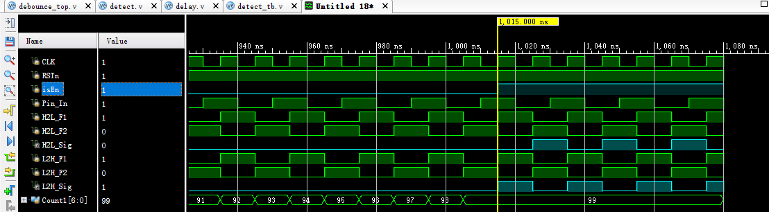
其检测模块的波形仿真文件如下图所示:
三、10ms延迟模块及测试激励文件
module delay(
input CLK,
input RSTn,
input H2L_Sig,
input L2H_Sig,
output Pin_Out
);
/*********************************************************************/
parameter T1MS=17'd99_999;
/************************************************************************/
/***************---1ms定时器---*************************************************/
reg [16:0]Count1;
always@(posedge CLK or negedge RSTn)
if(!RSTn)
Count1<=17'd0;
else if(isCount && Count1==T1MS)
Count1<=17'd0;
else if(isCount)
Count1<=Count1+1'b1;
else if(!isCount)
Count1<=17'd0;
/****************---计数器--******************************************************/
reg [3:0]Count_MS;
always@(posedge CLK or negedge RSTn)
if(!RSTn)
Count_MS<=4'd0;
else if(isCount && Count1==T1MS)
Count_MS<=Count_MS+1'b1;
else if(!isCount)
Count_MS<=4'd0;
/*******仿顺序操作,由i寄存器来控制执行的步骤***************************************************************************/
reg isCount;
reg rPin_Out;
reg [1:0] i;
always@(posedge CLK or negedge RSTn)
if(!RSTn)
begin
isCount<=1'b0;
rPin_Out<=1'b0;
i<=2'd0;
end
else
case(i)
2'd0:
if(H2L_Sig)i<=2'd1;
else if(L2H_Sig)i<=2'd2;
2'd1:
if(Count_MS==4'd10)begin isCount<=1'b0;rPin_Out<=1'b1;i<=2'd0;end
else isCount<=1'b1;
2'd2:
if(Count_MS==4'd10)begin isCount<=1'b0;rPin_Out<=1'b0;i<=2'd0;end
else isCount<=1'b1;
endcase
/***********************************************************************/
assign Pin_Out=rPin_Out;
/***********************************************************************/
endmodule
四、顶层模块及测试激励文件
module debounce_top(
input CLK,
input RSTn,
input Pin_In,
output Pin_Out
);
/*****************************************/
wire H2L_Sig;
wire L2H_Sig;
detect U1(
.CLK(CLK),
.RSTn(RSTn),
.Pin_In(Pin_In), //input-from top
.H2L_Sig(H2L_Sig), //output -to U2
.L2H_Sig(L2H_Sig) //output -to U2
);
/*********************************************/
delay U2(
.CLK(CLK),
.RSTn(RSTn),
.H2L_Sig(H2L_Sig), //input-from U1
.L2H_Sig(L2H_Sig), //input-from U1
.Pin_Out(Pin_Out)
);
/***************************************************/
endmodule