转自:http://www.8051projects.net/forum-t15092.html
| Author | Post | ||||
| digital-guy |
| ||||
| |
hi, I am a beginner when it comes to hardware so i though that i should get some help. I want to make this temperature controlled fan and since i am using 15V AC power supply instead of 230V AC. what i want to know is if i would have to change the triac and the resister shown in the diagram below and also if i can use MOC3041 Triac driver optoisolator (RC) instead of MOC3011 ?? any help will be much appreciated.  | ||||
| Back to top |
| ||||
| Arun Kumar V |
| ||||
 |
the chances are that the opto isolator/driver may not work at such low voltages. the triac will work. you can get rid of the MOC3021/11/41, if you can rectify the 15 VAC into DC and directly use the triac (or SCR) with 1K resistor to its gate and use a normal optocoupler like PC817 or MCT2E Arun [ Edited Wed Dec 03 2008, 02:08AM ] | ||||
| Back to top |
| ||||
| digital-guy |
| ||||
| |
thankyou for your reply arun. but from this all i understand soo far is to keep everything in the circuit and replace the MOC3011 with optocoupler as shown in the diag below. what i dont understand is to where to put the rectifier on the circuit. I mean if i convert the ac to dc, what value of dc would this give me? and if i am converting ac into dc then can i use both ac and dc fans ??? can i use optocoupler ISP815 instead of pc817 or mct2e because i cant find them. and can i also use "DF01 BRIDGE RECTIFIER 1A DIL4 RC" on my circuit? sorry to ask u soo many questions but i'm soo confuesd  updated diagram: http://www.geocities.com/niu_logic/circuit_diagram2.GIF PS: the fan is 15V AC and the rest of the information is on the circuit diagram in the link above. [ Edited Wed Dec 03 2008, 06:16AM ] | ||||
| Back to top |
| ||||
| Arun Kumar V |
| ||||
|
|
Hello digital-guy ( nice name like Cable -Guy) i have drawn the circuit to make things clear, pl.go thru it :  Arun | ||||
| Back to top |
| ||||
| digital-guy |
| ||||
| |
hello arun... good thing that u like my name  i was just wondering if the rectifier converts the 15Vac into 15Vdc can i just use a 15V or something dc power supply and remove the rectifier from the circuit? and also on ur diagram above u have 5pins for the optocoupler. pin5 for +5V dc, pin4 going into resistor and what about the rest, is pin1 going into the port 22 of the microcontroller and where are the rest of the pins going? | ||||
| Back to top |
| ||||
| Arun Kumar V |
| ||||
|
|
Hello digital-guy, First things first - tell me which supply are you actually using for the Fan motor ? AC or DC Yes, if you use DC supply for fan then you can remove the bridge ( but you first said you had 15V AC ). The LED part of the optocoupler in my diagram should be connected the same way its in your original schematic. and you don't have to connect the pin 6 ( collector), leave it floating. I think you have to be clear in what you intend to do, you had first said you have a 15V AC supply for fan and now you are saying you have 15VDC supply - if the latter is true then you can simply use a power mosfet to run the DC fan ( BTW you haven't said anything about fan's wattage). Arun | ||||
| Back to top |
| ||||
| digital-guy |
| ||||
| |
. [ Edited Fri Dec 05 2008, 01:51AM ] | ||||
| Back to top |
| ||||
| digital-guy |
| ||||
| |
hello arun im very sorry if i have not made it clear about my power supply. basically i am still thinking about the power supply and which one to use. looking at my options now...i think i should use a 15V dc power supply as i wont have to use the bridge. this also means i should use a 15V dc fan. So u mean the circuit should look like this below if i am using 15v dc power supply and 15v dc fan.  | ||||
| Back to top |
| ||||
| Ajay Bhargav |
| ||||
Rickey's World Admin |
if you are using DC power supply then you can control your fan with a darlington transistor or a simple optocoupler, you need not to have a triac there. or you can make use of dc motor driver like L293D (see tutorial for more information) its easy to use and controls motor over good range of voltage and current. http://www.8051projects.net/out.php?link=http://www.rickeyworld.info/ If you feel satisfied with the user's forum reply please click on the thank button. Obey forum rules! Respect others! | ||||
| Back to top |
| ||||
| Arun Kumar V |
| ||||
|
|
hello digital -Guy, to make things simple, use the circuit i had given on "Wed Dec 03 2008, 09:06PM" it works for both AC and DC Fans. use AC supply if you use AC fan, use DC supply if you use DC fan, in both the cases no changes are to be done in the circuit diagram. hope this clears your confusion. Arun | ||||
| digital-guy |
| ||||
| |
hello arun thanks for making it very simple for ppl like me to understand....really appreciated it. but 1 little question just to make sure i got it right.. now that i am using 15vDC power supply would the circuit look like this below and the triac in the diagram is BT136 which i can find but which one is the optocoupler model. i also noticed that u said that the led part of the optocoupler should be connected in the same way as it was with the moc3011. but in moc3011 on the left hand side, the upper pin(pin1) is going to 5v dc and the lower pin2 one going to port22 of 8051. pin6 into triac and pin4 into resistor. but in optocoupler pin4 is connected to the resistor which is connected to triac and pin5 is connected to 5v DC. and im assuming the pin2 is going into port22 of 8051 and pin1 to 5v dc if i am right ?  | ||||
| Back to top |
| ||||
| Arun Kumar V |
| ||||
|
|
digital guy, you can use any general opto like : PC817, MCT2E, 4N25, ........ etc if you have any other opto on hand then search for its datasheet to know its pin out. pin out of MOC3011/21/41 etc are different from other optos so don't be rigid on pin numbers. opto connections: ( for any optocoupler) LED side : Anode to + 5Vdc, cathode to pin 22 of micro thru series resistor 330ohms. transistor side : collector to +5dc, emitter to gate of SCR/Triac/transistor/mosfet thru a series resistor of 1 K. don't forget to connect GND of your 15 Vdc and 5 Vdc supply together ( if there are derived from separate sources) it cannot be more simpler than this, i hope Arun | ||||
| Back to top |
| ||||
| digital-guy |
| ||||
| |
hi arun thanks for making it soo much easier for me to understand i was just wondering if the assembly code for the circuit will be the same for the circuit with moc3011 and 203V ac power supply at (http://www.8051projects.net/downloads170.html) and it will work in the same way and have the same features. | ||||
| Back to top |
| ||||
| digital-guy |
| ||||
| |
hi every1 i just wanted to ask something about the 7 segment led display that i am using i am using dual digit 7segment " kingsbright DA56-11SRWA". it has 18 pins 9 on top and 9 on bottom i just wanted to ask how i should connect it in the same way as the diagram below. there are no pin letters ( a,b,c etc) and there seem to be no dp pin as only 7 lines from microcontroller are used. i am using a breadboard. your help would be much appreciated thankyou  | ||||
| Back to top |
| ||||
| Arun Kumar V |
| ||||
|
|
Hello Digital-Guy, in the above schematic the multiplexed seven segment LED display is connected to Port0, about the connections- port0.0 is connected to segment "a", port0.1 to "b"...... so on upto port0.6 which is connected to "g". since the dp is not used port0.7 is left unconnected. its always better to use pull-up resistors for port0 which are obviously missing in the above circuit. and here's datasheet of the LED display is you don't have it 836779e2ed.pdfArun | ||||
| Back to top |
| ||||
| digital-guy |
| ||||
| |
hi arun this part of the circuit is attached to port 13 of the 8051. and if i am not mistaken it just converts 230V ac into 5v dc. since i wont need this part as im already using a power supply that can produce 5, 12 and 15 v dc. so do i just connect 5v dc into port 13 of microcontroller??  | ||||
| Back to top |
| ||||
| Arun Kumar V |
| ||||
|
|
Hello Digital Guy, if i am not mistaken it just converts 230V ac into 5v dc. since i wont need this part as im already using a power supply that can produce 5, 12 and 15 v dc. so do i just connect 5v dc into port 13 of microcontroller?? No, its not just mere Power supply but its also a ZERO CROSS Detector circuitry built around dual OP-AMP which sends square wave pulse to micro at pin 13, so that the micro knows when it can "fire" the Triac. Arun | ||||
| Back to top |
| ||||
| digital-guy |
| ||||
| |
hi again arun so i dont really need it for everything to function properly...right? and the other thing is that the 7 seg dual display has 18 pins, like shown below. can i connect all the a,b,c,d....g's togather for both dual 7 segments except the connections going to the transistor. and are the connections going to the transistors are as shown below??? or is it a different pin of 7 seg?? in other words are the first 8 pins are as follows; a b c d e f g dp and transistor pin and the same for the 9 pins below for the same dual 7 seg led display.(common anode). and the pins that do go to the transistor, do they go into the emitter of the transistor? 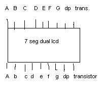 [ Edited Mon Dec 29 2008, 10:09PM ] | ||||
| Back to top |
| ||||
| sashijoseph |
| ||||
 |
The datasheet has a different pinout than you've posted.... like pin1 is 'e',pin2 is 'd' etc. hope you're following the correct pinout. Pins 14 and 13 are the common anode pins of the 2 displays and connect to the emitters of the transistors as shown in your schematic. And yes you may connect the respective a,b,c.. segments of both displays.  Let there be music........ | ||||
| Back to top |
| ||||
| digital-guy |
| ||||
| |
hi sashijoseph does this mean that the connections would look like this.? sorry about this....i just like to visualise everything before making it final   | ||||
| sashijoseph |
| ||||
|
|
According to the datasheet posted earlier,it's like this. Why don't you take a multimeter,connect one probe to the common anode pin and the other to the cathodes,one by one, and check for yourself. Your approach is good ... better to clear things up beforehand,rather than learn it the hard way. Let there be music........ | ||||
| Back to top |
| ||||
| digital-guy |
| ||||
| |
hi arun...i have finally got all the components and started building ... i have more or less completed the hardware part but 1 thing remains doubtful... u said to connect p22 of 8051 to led cathode using 330ohm...but in the diagram it says u should connect p24 of microcontroller instead of p22... would this make any difference or is it same?? i have connected the gate of bt136 tirac to the emitter of 4n25 using 1k and connected +5dc to anode and collector of 4n25. what i m not sure about is what to connect to the remaining pins of triac.. pin 1 and 2, terminal1 and 2. i'm using a power supply with built in +12 +5 0 -5 -12 VDc. which connection goes where???? on the triac and i'm also going to use +12vDc motor. will really appreciate ure response | ||||
| Back to top |
| ||||
| sashijoseph |
| ||||
|
|
digital-guy wrote ...
but in the diagram it says u should connect p24 of microcontroller instead of p22... would this make any difference or is it same?? Which diagram? In the schematic in your 1st post,Pin22 is connected to the opto...so it should be that way unless you intend to change the code. Let there be music........ | ||||
| Back to top |
| ||||
| digital-guy |
| ||||
| |
i have finished the hardware and programmed the 8051...when i power the circuit on, the 2X dual 7seg display reads blank 0 0 9 and when i press the button for switching between auto and manual mode...it reads " blank u t o " then " blank n f f" and when i press it again " blank u t o" then " blank n blank blank". basically the first digit is not working and the other have problems either with hardware or software... i have followed the pin description given in the code e.g. DIS_A EQU P0.2 DIS_B EQU P0.3 DIS_C EQU P0.4 DIS_D EQU P0.6 DIS_E EQU P0.5 DIS_F EQU P0.1 DIS_G EQU P0.0 DIS1 EQU P0.7 DIS2 EQU P2.7 DIS3 EQU P2.6 DIS4 EQU P2.5 PLUS EQU P1.0 MINUS EQU P1.1 AUTO EQU P1.2 AUTO_LED EQU P1.3 "" and also the display doesnt show the room temperature or allow me to amend the temperature range in the auto mode.... what am i doing wrong....please help  | ||||
| Back to top |
| ||||
| digital-guy |
| ||||
| |
i have a question... how does the speed of the fan get controlled by port 22 of microcontroller. can any 1 explain the concepts of it thankyou | ||||
| Back to top |
| ||||
| Arun Kumar V |
| ||||
|
|
simple, pin22 switches the fan "ON" or "OFF" thru the optocoupler when temp exceeds certain limit and when the temp comes down ( bcoz of the fan running cools the place) the fan is switched "OFF". Arun | ||||
| Back to top |
| ||||
| digital-guy |
| ||||
| |
i understand this... but how can the voltage going to the fan be varied... eg how can the speed of the fan be in different levels for example speed ranging from 1- 9. how can this be done | ||||
| Back to top |
| ||||
| ExperimenterUK |
| ||||
| |
digital-guy wrote ...
i understand this... but how can the voltage going to the fan be varied... eg how can the speed of the fan be in different levels for example speed ranging from 1- 9. how can this be done The switching happens very quickly.. power on the fan runs full speed, power off it stops, pulsing the power averages the speed to somewhere in between. | ||||
| Back to top |
| ||||
| digital-guy |
| ||||
| |
i can set the port to 1 (setb) to switch on or clr to off the fan... but how would i chose the speed in between or increment the fan speed | ||||
| Back to top |
| ||||
| Arun Kumar V |
| ||||
|
|
firstly digital-guy, you have not posted the full schematic of the project, on the first page you just have posted main portion but i guess( i strongly remember) that the second schematic of the project contains ZCD ( Zero Crossing Detector) built around op-amp LM358 and this is required for varying the Fan Speed. BTW, finally what supply are you using for the fan AC or DC. now for the speed control part, lets assume the AC mains freq is 50Hz i,e 0.02 sec and every half cycle the i,e 0.01sec the voltage changes phase and passes thru zero state, this zero crossing input is fed to the micro thru an interrupt pin and the micro now knows that the voltage is near zero( there is delay by the time the micro responds to the interrupt) so it can be any where between 0-10volts, at this point the micro fires the triac /SCR thru the optocoupler, remember the micro has 0.01sec to fire the triac/SCR, if full speed is required then the micro fires the triac/scr immediately after the ZCD interrupt and very lately for slow speed i,e at the later portion of 0.01sec. this how it all happens and it happens very rapidly. for more info you can google for " Phase controlled firing of Triac/SCR" or "AC Lamp Dimmer" | ||||
| digital-guy |
| ||||
| Registered Member #12761 Joined: Tue Dec 02 2008, 11:16PMLocation: nepal Posts: 35 Thanked 0 times in 0 posts |
sorry about the full schematic....the 2nd part is attached at the moment i only have access to a DC powersupply producing 5,12 and 15 V. triacs are commonly used with ac and thyristors with dc....does that mean thyrisistor is more suitable for me? and how would i go about the ZCD part of the circuit without using an ac power supply ?  | ||||
| Back to top |
| ||||
| digital-guy |
| ||||
| Registered Member #12761 Joined: Tue Dec 02 2008, 11:16PMLocation: nepal Posts: 35 Thanked 0 times in 0 posts |
can i use a PWM driver instead of this part of the circuit to generate a pulse which will in turn increase or reduce the voltage. | ||||
| Back to top |
| ||||
| Arun Kumar V |
| ||||
|
Registered Member #426 Joined: Mon Jan 29 2007, 02:57PMLocation: Hyderabad-India Posts: 679 Thanked 274 times in 234 posts |
can i use a PWM driver instead of this part of the circuit to generate a pulse which will in turn increase or reduce the voltage. which driver do you want to use ? you can use a software generated PWM using 8051 which then requires a devoted timer. the above project can be modified to accommodate PWM, but see if there is a spare timer available (one timer is already used for multiplexing the display). you can go thru the PWM tutorial on our site for more info. Arun | ||||
| Back to top |
| ||||
| Nirmaan |
| ||||
| Registered Member #12472 Joined: Sun Nov 23 2008, 10:32PMLocation: Karnataka Posts: 9 Thanked 1 time in 1 posts |
@digital-guy, i think you are getting free help but forgetting to thank the moderators, Mr.Arun has clearly explained how the AC fan speed control works and you'll seldom find people who explain the concept in simple terms. | ||||
| Back to top |
| ||||
| digital-guy |
| ||||
| Registered Member #12761 Joined: Tue Dec 02 2008, 11:16PMLocation: nepal Posts: 35 Thanked 0 times in 0 posts |
in the code timer1 has been set ( setb tr1) and tr0 has been used for fan speeds. will software generated pwm be in assembly lang and if i can use the pwm then would this mean that my circuit is "complete" . may be if i cannot use the time then would i be able to interface adc with 8051 ? | ||||
| Back to top |
| ||||
| digital-guy |
| ||||
| Registered Member #12761 Joined: Tue Dec 02 2008, 11:16PMLocation: nepal Posts: 35 Thanked 0 times in 0 posts |
Nirmaan wrote ...
@digital-guy, i think you are getting free help but forgetting to thank the moderators, Mr.Arun has clearly explained how the AC fan speed control works and you'll seldom find people who explain the concept in simple terms. i do thank mr arun kumar for his kind help... but the whole point of this project is to create a DC and not AC fan. i think people should read the whole topic before throwing their questions at other people. | ||||
| Back to top |
| ||||
| Arun Kumar V |
| ||||
|
Registered Member #426 Joined: Mon Jan 29 2007, 02:57PMLocation: Hyderabad-India Posts: 679 Thanked 274 times in 234 posts |
may be if i cannot use the time then would i be able to interface adc with 8051 ? why do you want to interface ADC to 8051 to control the speed of DC fan ? i advice you to go thru the PWM tutorial once again and try to see if you can dedicate a spare timer for this job. Arun | ||||
| Back to top |
| ||||
| digital-guy |
| ||||
| Registered Member #12761 Joined: Tue Dec 02 2008, 11:16PMLocation: nepal Posts: 35 Thanked 0 times in 0 posts |
hi arun since i'm not very good at assembly please correct me where u can... i understand now the concepts of pwn...basically the voltage depends on how long T.on is. and the maximum voltage e.g. full speed of the fan can be achieved by removing the timer and hence you get Vin. so does this mean the Vin is the voltage input from the microcontroller (5V)??? or the 12V for the fan???? anyway... for fan off ORG 0 SJMP START ORG 03H SJMP CHECK ORG 40H START: MOV P1,#0CFH SETB IT0 MOV IEN0,#81H STAY: SJMP STAY CHECK: JNB P1.0,REVERSE JNB P1.1,SPEED1 JNB P1.2,SPEED2 SJMP CHECK SPEED1: ANL CCAPM2,#0FDH CLR P1.5 ORL CCAPM1,#42H MOV CCAP1L,#102 MOV CCAP1H,#102 ORL CCON,#40H RETI SPEED2: ANL CCAPM2,#0FDH CLR P1.5 ORL CCAPM1,#42H MOV CCAP1L,#26 MOV CCAP1H,#26 ORL CCON,#40H RETI this is what i know ... i am confused about how the value or the ratio (voltage) i can increment/decrement by pressing buttons and also this is for manual mode... can u please give me some guidence on how to go about doing the same for auto mode. and also what about my hardware??? would i stil look like before (attached below)...or now that i am using pwm... it will look different...because i may need to use transistor instead of a tirac i'm really sorry if im asking too many q's...just need to b clear... thats all:-)  | ||||
| Back to top |
| ||||
| ExperimenterUK |
| ||||
| Registered Member #9602 Joined: Wed Aug 06 2008, 07:22AMLocation: Manchester Posts: 721 Thanked 122 times in 121 posts |
You will need to use a transistor instead of a triac. A triac will not reliably switch off DC in this case. The good news is that using such a low voltage you don't need the opto-isolator. The transistor can be connected to pin 22 via a resitor. You probably need to keep R10 as a pull up. [ Edited Fri Feb 06 2009, 07:55AM ] | ||||
| Back to top |
| ||||
| digital-guy |
| ||||
| Registered Member #12761 Joined: Tue Dec 02 2008, 11:16PMLocation: nepal Posts: 35 Thanked 0 times in 0 posts |
so do i just need a normal (2n2222) transistor? i will need to drive a 12V dc motor | ||||
| Author | Post | ||||
| Ajay Bhargav |
| ||||
| Rickey's World Admin Registered Member #1 Joined: Fri Feb 24 2006, 08:03PMLocation: Punjab, India Posts: 5627 Thanked 1028 times in 969 posts |
yes that one will be fine, you need to connect a Diode across motor to prevent back emf. http://www.8051projects.net/out.php?link=http://www.rickeyworld.info/ If you feel satisfied with the user's forum reply please click on the thank button. Obey forum rules! Respect others! | ||||
| Back to top |
| ||||
| Arun Kumar V |
| ||||
|
Registered Member #426 Joined: Mon Jan 29 2007, 02:57PMLocation: Hyderabad-India Posts: 679 Thanked 274 times in 234 posts |
so do i just need a normal (2n2222) transistor? i will need to drive a 12V dc motor yes that one will be fine, you need to connect a Diode across motor to prevent back emf. without knowing the rating of your DC 12 V motor if you connect it to the poor 2n2222 transi you could see smoke coming up ! first find out what is the motor's current consumption using multimeter, i,e how much milliamps/amps the motor draws when connected to +12 Volts micro like 8051 can only provide(source) 1 mA current @ 5 volts and that small current is not sufficient to turn ON a transistor fully, so better use a darlington transistor ( which has 2 transi inside, one with high gain and the other with high power) or even better a mosfet N channel . all this can be ascertained only if we know the current consumption of the DC motor. Arun | ||||
| Back to top |
| ||||
| digital-guy |
| ||||
| Registered Member #12761 Joined: Tue Dec 02 2008, 11:16PMLocation: nepal Posts: 35 Thanked 0 times in 0 posts |
hi so the only thing different on my hardware is that i replace the tirac with the darlington transistor...and i would stil need opto-isolator as i want to separate 5v from uC and 12v for fan...rite ?? how would i connect the transistor to my 12V and the opto isolator ?? and also can u please check my code that i posted earlier ... | ||||
| Back to top |
| ||||
| Arun Kumar V |
| ||||
|
Registered Member #426 Joined: Mon Jan 29 2007, 02:57PMLocation: Hyderabad-India Posts: 679 Thanked 274 times in 234 posts |
first find out what is the motor's current consumption using multimeter, i,e how much milliamps/amps the motor draws when connected to +12 Volts all this can be ascertained only if we know the current consumption of the DC motor. you haven't given the current consumption, yet and i would stil need opto-isolator as i want to separate 5v from uC and 12v for fan...rite ?? opto-coupler is not required, but you can use it only to protect the micro from EMI from motor. even without opto, it will work. Arun | ||||
| Back to top |
| ||||
| digital-guy |
| ||||
| Registered Member #12761 Joined: Tue Dec 02 2008, 11:16PMLocation: nepal Posts: 35 Thanked 0 times in 0 posts |
i was planning to use a multimeter instead of motor for now to see the variation in voltages and if it all goes accordin to plan...but i want to use a 12Vdc , 14.4W, 1200mA fan...if possible with current configurations. so since there might not be any need for opto-isolator and tirac... would the pin22 from uC go straight into the darlington transistor??? | ||||
| Back to top |
| ||||
| sashijoseph |
| ||||
|
Registered Member #5870 Joined: Tue Feb 05 2008, 09:33AMLocation: Jamshedpur Posts: 719 Thanked 161 times in 154 posts |
not straight,but through a 1k current limiting resistor into the base. You may use an npn darlington like TIP121 for the job.... Let there be music........ | ||||
| Back to top |
| ||||
| Arun Kumar V |
| ||||
|
Registered Member #426 Joined: Mon Jan 29 2007, 02:57PMLocation: Hyderabad-India Posts: 679 Thanked 274 times in 234 posts |
Now after seeing your Dc Fan's current rating, you can surely not use puny transistors like 2n2222 or BC337 etc since your fan consumes quiet amount of current, you have to use a N- channel Power mosfet like IRFZ44N or IRF540N they are easily available bcoz they are extensively used in UPS and Inverters. and yes you can directly connect the Port pin22 ( with a pull up already installed) to the gate of the mosfet without any series resistor between the port pin and the gate of the mosfet bcoz mosfets are voltage driven devices unlike transistors which are current driven. Arun Arun | ||||
| Back to top |
| ||||
| digital-guy |
| ||||
| Registered Member #12761 Joined: Tue Dec 02 2008, 11:16PMLocation: nepal Posts: 35 Thanked 0 times in 0 posts |
can i use any power mosfet as long as it has the same specs of irf540n e.g. VDss 100V, RDS(on) 40m ohm, ID 33A. ? and pin22 will go into the Gate? and 12V go into the source and the fan's +ve wire go into the drain and the fan's -ve wire into the ground ?? | ||||
| Back to top |
| ||||
| Arun Kumar V |
| ||||
|
Registered Member #426 Joined: Mon Jan 29 2007, 02:57PMLocation: Hyderabad-India Posts: 679 Thanked 274 times in 234 posts |
Be careful, you have to use N-channel power mosfet and pin22 will go into the Gate? and 12V go into the source and the fan's +ve wire go into the drain and the fan's -ve wire into the ground ?? your connection is wrong, its connected like this; pin22 (with a 10K pull up already connected) to the gate (without any series resistor), +12 Volts to Fan's positive and fan's negative wire connected to the Drain of Mosfet, source is connected to Ground. you should have a diode across the motor to protect the mosfet from EMF back kicks. just like you have diode across a relay. here's diagram to clear things (diode is missing though)  Arun | ||||
| Back to top |
| ||||
| digital-guy |
| ||||
| Registered Member #12761 Joined: Tue Dec 02 2008, 11:16PMLocation: nepal Posts: 35 Thanked 0 times in 0 posts |
so will the diode be placed as it is on the diagram below? and which type of diode i need... i noticed you have 2 connections going to the gate... shall i just ignore one and do the one with p22 without the 10k. and can i use any mosfet as long as it has the same specs as IRFZ46N ??? i also forgot to mention that i am using an 8pin ds1820 instead of a 3 pin one... would it matter if i connect it up in the same..??  [ Edited Mon Feb 09 2009, 09:35PM ] | ||||
| Arun Kumar V |
| ||||
|
Registered Member #426 Joined: Mon Jan 29 2007, 02:57PMLocation: Hyderabad-India Posts: 679 Thanked 274 times in 234 posts |
digital -guy, you are lucky that you are posting your doubts in our forum, if you would have posted your doubts in some other forum, i think the people there would ask you to go and learn basic electronics and then try using Micros. i had clearly explained in my above posts how you have to set the things with help of diagrams, i had asked to connect the diode across the motor, now in your diagram where have you connected it - in series with motor, and with this set up do you think the motor will work - the current passing thru motor will be blocked by the diode and will never reach the drain of mosfet. now in all these pages of the post we have talking about pin22 of the micro, and in the last post too i have been time and again mentioning about the pin22 nad 10K pullup resistor. anyway, here is the diagram; 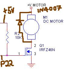 Arun | ||||
| Back to top |
| ||||
| digital-guy |
| ||||
| Registered Member #12761 Joined: Tue Dec 02 2008, 11:16PMLocation: nepal Posts: 35 Thanked 0 times in 0 posts |
hi arun i cant thank u enough for all the help and support you have given me so far... i really appreciate it. i hope this will in future help ppl like me to understand the concepts... so i understand that the hardware is now complete... since i'm starting with a code for a 230v ac fan with zero crossing detector...how will i need to modify it and use with current hardware PS: is there any program that converts assembly code into C language or vise versa and just to confirm...i can program 8051 in c rite? [ Edited Tue Feb 10 2009, 06:52AM ] | ||||
| Back to top |
| ||||
| Arun Kumar V |
| ||||
|
Registered Member #426 Joined: Mon Jan 29 2007, 02:57PMLocation: Hyderabad-India Posts: 679 Thanked 274 times in 234 posts |
PS: is there any program that converts assembly code into C language or vise versa and just to confirm...i can program 8051 in c rite? there are some applications which convert assembly code into C code but they are too expensive and not advisable. here's one such software : http://www.textmaestro.com/InfoEx_17_Convert_Assembly.htm you can write program in C for 8051( for that matter any micro). Arun | ||||
| Back to top |
| ||||
| digital-guy |
| ||||
| Registered Member #12761 Joined: Tue Dec 02 2008, 11:16PMLocation: nepal Posts: 35 Thanked 0 times in 0 posts |
i was wondering if i can program the uC in c and assembly at the same time... e.g. code for lcd and buttons in c and the rest in assembly ? if yes then how would i do it before i convert it into hex. | ||||
| Back to top |
| ||||
| digital-guy |
| ||||
| Registered Member #12761 Joined: Tue Dec 02 2008, 11:16PMLocation: nepal Posts: 35 Thanked 0 times in 0 posts |
i have a question that i cant seem to find an answer to... when i connect my circuit in the following way...i dont know if u can see but connection 1 goes to p32 of uC and is also connected to the transistor for the 1st 7seg display connection 2 goes to p22 of uC. each time the temperature goes beyond the 24 degrees... the fan is suppose to turn on. and if i measure the voltage connected in the same way as above... it only gives me about 1.4V and if i measure the voltage from the collector with respect to ground it only gives me 10mV and if i connect one end of multimeter to collecor and the other to 12V...it only gives me about 3.23... V (i have used a bc547 and tip122darlington n channel)...why am i getting so low voltage???...i cant even move a little 5v fan with this configurations.  | ||||
| Back to top |
| ||||
| ExperimenterUK |
| ||||
| Registered Member #9602 Joined: Wed Aug 06 2008, 07:22AMLocation: Manchester Posts: 721 Thanked 122 times in 121 posts |
wrote ...
i was wondering if i can program the uC in c and assembly at the same time... e.g. code for lcd and buttons in c and the rest in assembly ? if yes then how would i do it before i convert it into hex. Yes you can. Most compilers use the keyword "asm" to allow you to insert assembly blocks as in this made up snippet. asm { add a,1 mov b,a } FET transistors need virtually no current to operate so the a 10k resistor is fine. bc547 and tip122 and not FETs and need much more current to operate. Change R2 to 1K, use a TIP122 and see what happens. That said, your circuit should be able drive the meter to show 4.8 volts when fully on, but you will only get that when the temperature is well above the set point. One possibility is that you have not connected the transistor correctly check the pin connections again.. and again [ Edited Tue Feb 24 2009, 07:34AM ] | ||||
| Back to top |
| ||||
| Arun Kumar V |
| ||||
|
Registered Member #426 Joined: Mon Jan 29 2007, 02:57PMLocation: Hyderabad-India Posts: 679 Thanked 274 times in 234 posts |
(i have used a bc547 and tip122darlington n channel) No, you haven't used an N channel mosfet, what your schematic shows is a NPN transistor and the VCC is 5V not 12V as you claim in your post. Arun | ||||
| Back to top |
| ||||
| digital-guy |
| ||||
| Registered Member #12761 Joined: Tue Dec 02 2008, 11:16PMLocation: nepal Posts: 35 Thanked 0 times in 0 posts |
hi arun i'm sorry that my schematic shows a normal npn transistor...i just put it there as i have used 2 different transistors like bc547 and tip122. and ExperimenterUK... i have checked my connections and tried R2 as 1k but it turns off the 2nd 7seg as r1(connected with transistor for 2nd 7seg) and r2 have a joint connection to 5V at that point... i have had more success with using a relay... and it does trigger when the temp goes higher than the limit and gives me around 4.5v on multimeter when i connect the output of relay with respect to +5v... but when i connect the 5v fan....everything just goes off like it is short circuited... | ||||
| Back to top |
| ||||
| ExperimenterUK |
| ||||
| Registered Member #9602 Joined: Wed Aug 06 2008, 07:22AMLocation: Manchester Posts: 721 Thanked 122 times in 121 posts |
digital-guy wrote ...
i have checked my connections and tried R2 as 1k but it turns off the 2nd 7seg as r1(connected with transistor for 2nd 7seg) and r2 have a joint connection to 5V at that point... If your circuit is wired as in the diagram the 2nd 7seg will not be affected. I suspect you have a bad connection somewhere, so that the R1-R2 junction is not connected to 5 volts. Or perhaps your supply is weak. While testing, write a simple program that just turns on pin 22. [ Edited Fri Feb 27 2009, 07:08AM ] | ||||
| Back to top |
| ||||
| digital-guy |
| ||||
| Registered Member #12761 Joined: Tue Dec 02 2008, 11:16PMLocation: nepal Posts: 35 Thanked 0 times in 0 posts |
thankyou all for helping me soo much to finish the hardware. at the moment i have a program for the 8051 that only makes the fan run at 1 speed. for example if the temperature goes above the limit the fan turns on and stays on until the room temp goes below the limit. what i want is with the help of pwm add fan 4 fan speeds e.g. 1/4 power, 1/2,3/4 and 4/4 power in such a way that when: current temp = set temp then its 1/4 power is applied current temp - set temp = 1 then its 1/2 power c temp - s temp = 2 its 3/4 and anything above it the fan is on full speed. i cant seem to figure out what is wrong with the code here is the code to make the fan run at 1/2 power ; MOV A,NUMB3 ; stored temp ;MOV B, R3 ;room temp ;CJNE A, B, TWO ;SETB ALARM ; fan does turn on when equal but doesnt when incremented ; JMP EDE ;TWO: MOV A, NUMB3 ;INC A ;MOV B, R3 ;CJNE A, B, THRE ;SETB ALARM ;MOV R5, #25 ;ACALL DLAYY ;CLR ALARM ;MOV R5, #75 ;ACALL DLAYY ;DLAYY: ;H1: MOV R2, #100 ;H2: MOV R3, #255 ;H3: DJNZ R3, H3 ;DJNZ R2, H2 ;DJNZ R5, H1 ;RET please point me to the right direction | ||||
| digital-guy |
| ||||
| Registered Member #12761 Joined: Tue Dec 02 2008, 11:16PMLocation: nepal Posts: 35 Thanked 0 times in 0 posts |
hi all... i was wondering how the "swap" command works in assembly and i couldnt find any info on it for example if i have a number e.g. 05H and 0101B what would happen if i apply swap is the answer 50H and 1100B ?? and i want to apply or logic to them lets say 0011 ORL 0110 and 50H ORL 04H and also i wanted to know why some people connect pin 9 of 8051 in between a 1uF capacitor and 56k resistor...capacitor connected to 5V and resistor to GND ...all this instead of connecting to 5v with switch for reset ? any response would be appreciated [ Edited Sun Mar 29 2009, 07:43PM ] | ||||
| Back to top |
| ||||
| Ajay Bhargav |
| ||||
| Rickey's World Admin Registered Member #1 Joined: Fri Feb 24 2006, 08:03PMLocation: Punjab, India Posts: 5627 Thanked 1028 times in 969 posts |
swap command interchanges higher nibble with lower nibble. i.e. if you swap 50H you will get 05H regarding reset. well it is required to connect a capacitor and resistor to form an RC circuit and give a high to low pulse on reset pin. more information on selection of RC you can get in Intel 8051 user manual. visit download section to download it. http://www.8051projects.net/out.php?link=http://www.rickeyworld.info/ If you feel satisfied with the user's forum reply please click on the thank button. Obey forum rules! Respect others! | ||||
| Back to top |
| ||||
| digital-guy |
| ||||
| Registered Member #12761 Joined: Tue Dec 02 2008, 11:16PMLocation: nepal Posts: 35 Thanked 0 times in 0 posts |
what if i want to apply or logic 0011 ORL 0110 and 50H ORL 04H what would the answer be? and why do we need high to low pulse on reset pin...cant we just replace it with reset push button with 5v? | ||||
| Back to top |
| ||||
| Ajay Bhargav |
| ||||
| Rickey's World Admin Registered Member #1 Joined: Fri Feb 24 2006, 08:03PMLocation: Punjab, India Posts: 5627 Thanked 1028 times in 969 posts |
0011 ORL 0110 => 0111 50H or 04H => 54H regarding reset read following..  http://www.8051projects.net/out.php?link=http://www.rickeyworld.info/ If you feel satisfied with the user's forum reply please click on the thank button. Obey forum rules! Respect others! | ||||
| Back to top |
| ||||
| digital-guy |
| ||||
| Registered Member #12761 Joined: Tue Dec 02 2008, 11:16PMLocation: nepal Posts: 35 Thanked 0 times in 0 posts |
hi... i was just wondering how do we select the frequency of the crystal that we used with uC why do we use 11.05.... and 12mhz and what would happen if we increase the size of the crystal... would the uC be faster??? | ||||
| Back to top |
| ||||
| Ajay Bhargav |
| ||||
| Rickey's World Admin Registered Member #1 Joined: Fri Feb 24 2006, 08:03PMLocation: Punjab, India Posts: 5627 Thanked 1028 times in 969 posts |
yes controller will be faster. well choosing a crystal depends on type or project you are working on.. like if you want faster execution of code then u choose to increase speed, but sometimes you feel problem when you are trying to communicate between two controllers using uart and baud rate doesnt come perfect. i cant explain this coz its more of a practical issue than just conceptual one. :0 http://www.8051projects.net/out.php?link=http://www.rickeyworld.info/ If you feel satisfied with the user's forum reply please click on the thank button. Obey forum rules! Respect others! | ||||
| Back to top |
| ||||
| digital-guy |
| ||||
| Registered Member #12761 Joined: Tue Dec 02 2008, 11:16PMLocation: nepal Posts: 35 Thanked 0 times in 0 posts |
hi... i was wondering what are the benefits of using a M74HC04 hex inverter. i have tried to trigger a 12v 40mA fan by using just a TIP 31c power transistor...but didnt work i tried again with using both tip31 and hex inverter and it worked... what i have been told is that hex inverter can boost the current to the fan (current buffer) if this is true then isnt the power transistor suppose to do the same?? and why do we need power transistor?? and cant we used the normal one? | ||||
| Back to top |
| ||||
| ExperimenterUK |
| ||||
| Registered Member #9602 Joined: Wed Aug 06 2008, 07:22AMLocation: Manchester Posts: 721 Thanked 122 times in 121 posts |
A tip31c should be able to drive a 40 mA fan without using a M74HC04. It may be that the fan needs more than 40 mA, or your circuit is wrong. Please post a diagram of your circuit. | ||||