http://www.cisco.com/c/en/us/support/docs/ip/open-shortest-path-first-ospf/7112-26.html
Introduction
A common problem when using Open Shortest Path First (OSPF) is routes in the database don't appear in the routing table. In most cases OSPF finds a discrepancy in the database so it doesn't install the route in the routing table. Often, you can see the Adv Router is not-reachable message (which means that the router advertising the LSA is not reachable through OSPF) on top of the link-state advertisement (LSA) in the database when this problem occurs. Here is an example:
Adv Router is not-reachable
LS age: 418
Options: (No TOS-capability, DC)
LS Type: Router Links
Link State ID: 172.16.32.2
Advertising Router: 172.16.32.2
LS Seq Number: 80000002
Checksum: 0xFA63
Length: 60
 Number of Links: 3
There are several reasons for this problem, most of which deal with mis-configuration or a broken topology. When the configuration is corrected the OSPF database discrepancy goes away and the routes appear in the routing table. This document explains some of the more common reasons that can cause the discrepancy in the database.
Some of the commands used throughout this document for verification of OSPF behavior include the show ip ospf interface, ip ospf database router, show ip ospf neighbor and the show ip ospf database external . If you have the output of any of these commands from your Cisco device, you can use Cisco CLI Analyzer to display potential issues and fixes. To use Cisco CLI Analyzer, you must be a registered customer, be logged in, and have JavaScript enabled.
Prerequisites
Requirements
Readers of this document should have knowledge of these topics
-
Basic Configuration of OSPF
Components Used
The information in this document is based on these software and hardware versions:
-
Cisco IOS® Software Release 12.3 was running on all routers.
-
This is supported on all Cisco router platforms.
The information in this document was created from the devices in a specific lab environment. All of the devices used in this document started with a cleared (default) configuration. If your network is live, make sure that you understand the potential impact of any command.
Conventions
For more information on document conventions, see the Cisco Technical Tips Conventions.
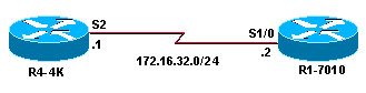
Reason 1: Network Type Mismatch
Let's use the following network diagram as an example:

| R4-4K | R1-7010 |
|---|---|
interface Loopback0 ip address 172.16.33.1 255.255.255.255 interface Serial2 ip address 172.16.32.1 255.255.255.0 ip ospf network broadcast router ospf 20 network 172.16.0.0 0.0.255.255 area 0 |
interface Loopback0 ip address 172.16.30.1 255.255.255.255 ! interface Serial1/0 ip address 172.16.32.2 255.255.255.0 clockrate 64000 router ospf 20 network 172.16.0.0 0.0.255.255 area 0 |
R4-4K(4)# show ip ospf interface serial 2
Serial2 is up, line protocol is up
  Internet Address 172.16.32.1/24, Area 0
  Process ID 20, Router ID 172.16.33.1, Network Type BROADCAST, Cost: 64
  Transmit Delay is 1 sec, State DR, Priority 1
  Designated Router (ID) 172.16.33.1, Interface address 172.16.32.1
  Backup Designated router (ID) 172.16.32.2, Interface address 172.16.32.2
  Timer intervals configured, Hello 10, Dead 40, Wait 40, Retransmit 5
    Hello due in 00:00:08
  Neighbor Count is 1, Adjacent neighbor count is 1
    Adjacent with neighbor 172.16.32.2  (Backup Designated Router)
  Suppress hello for 0 neighbor(s)

R1-7010(5)# show ip ospf interface serial 1/0
Serial1/0 is up, line protocol is up
  Internet Address 172.16.32.2/24, Area 0
  Process ID 20, Router ID 172.16.32.2, Network Type POINT_TO_POINT, Cost: 64
  Transmit Delay is 1 sec, State POINT_TO_POINT,
  Timer intervals configured, Hello 10, Dead 40, Wait 40, Retransmit 5
    Hello due in 00:00:02
  Neighbor Count is 1, Adjacent neighbor count is 1
    Adjacent with neighbor 172.16.33.1
  Suppress hello for 0 neighbor(s)
As you can see above, Router R4-4K is configured for broadcast, and Router R1-7010 is configured for point-to-point. This kind of network type mismatch makes the advertising router unreachable.
R4-4K(4)# show ip ospf database router 172.16.32.2

  Adv Router is not-reachable
  LS age: 418
  Options: (No TOS-capability, DC)
  LS Type: Router Links
  Link State ID: 172.16.32.2
  Advertising Router: 172.16.32.2
  LS Seq Number: 80000002
  Checksum: 0xFA63
  Length: 60
   Number of Links: 3

    Link connected to: another Router (point-to-point)
    (Link ID) Neighboring Router ID: 172.16.33.1
    (Link Data) Router Interface address: 172.16.32.2
    Number of TOS metrics: 0
    TOS 0 Metrics: 64

    Link connected to: a Stub Network
    (Link ID) Network/subnet number: 172.16.32.0
    (Link Data) Network Mask: 255.255.255.0
    Number of TOS metrics: 0
    TOS 0 Metrics: 64

R1-7010(5)# show ip ospf database router 172.16.33.1

  Adv Router is not-reachable
  LS age: 357
  Options: (No TOS-capability, DC)
  LS Type: Router Links
  Link State ID: 172.16.33.1
  Advertising Router: 172.16.33.1
  LS Seq Number: 8000000A
  Checksum: 0xD4AA
  Length: 48
   Number of Links: 2

     Link connected to: a Transit Network
     (Link ID) Designated Router address: 172.16.32.1
     (Link Data) Router Interface address: 172.16.32.1
     Number of TOS metrics: 0
     TOS 0 Metrics: 64
You can see that for subnet 172.16.32.0/24, Router R1-7010 is generating a point-to-point link and Router R4-4K is generating a transit link. This creates a discrepancy in the link-state database, which means no routes are installed in the routing table.
R1-7010(5)# show ip route
172.16.0.0/16 is variably subnetted, 3 subnets, 2 masks
C       172.16.32.0/24 is directly connected, Serial1/0
C       172.16.30.1/32 is directly connected, Loopback0
Solution
To solve this problem, configure both routers for the same network type. You can either change the network type of Router R1-7010 to broadcast, or change Router R4-4K's serial interface to point-to-point.
Note: If you have a situation where one side is a multipoint interface and the other side is a sub-interface then change the network type to broadcast on both sides.
In this example we have removed the "network-type broadcast" statement on R4-4K because both sides are point-to-point High-Level Data Link Control (HDLC) encapsulated interfaces.
R4-4K(4)# configure terminal
R4-4K(4)(config)# interface serial 2
R4-4K(4)(config-if)# no ip ospf network broadcast
R4-4K(4)(config-if)# end

R4-4K(4)# show ip ospf interface serial 2
 Serial2 is up, line protocol is up
  Internet Address 172.16.32.1/24, Area 0
  Process ID 20, Router ID 172.16.33.1, Network Type POINT_TO_POINT, Cost: 64
  Transmit Delay is 1 sec, State POINT_TO_POINT,
  Timer intervals configured, Hello 10, Dead 40, Wait 40, Retransmit 5
   Hello due in 00:00:04
  Neighbor Count is 1, Adjacent neighbor count is 1
  Adjacent with neighbor 172.16.32.2
  Suppress hello for 0 neighbor(s)
Reason 2: Wrong Address Assignment in Dual Serial Link Setup
Consider this network diagram as an example:

| R4-4K | R1-7010 |
|---|---|
interface loopback 0 ip address 172.16.35.1 255.255.255.255 interface Serial2 ip address 172.16.29.1 255.255.255.0 ! interface Serial3 ip address 172.16.32.1 255.255.255.0 router ospf 20 network 172.16.0.0 0.0.255.255 area 0 |
interface loopback 0 ip address 172.16.30.1 255.255.255.255 interface Serial1/0 ip address 172.16.32.2 255.255.255.0 clockrate 64000 ! interface Serial1/1 ip address 172.16.29.2 255.255.255.0 clockrate 38400 router ospf 20 network 172.16.0.0 0.0.255.255 area 0 |
You can see that the IP addresses are flipped in the above configurations, which causes a discrepancy in the OSPF database. However, the routers still form neighbors in Cisco IOS version earlier than 12.1 because on a point-to-point link, OSPF routers don't verify that the neighboring router is on the same subnet.
R4-4K(4)# show ip ospf neighbor

Neighbor ID     Pri   State           Dead Time   Address         Interface
172.16.32.2       1   FULL/  -        00:00:37    172.16.32.2     Serial2
172.16.32.2       1   FULL/  -        00:00:31    172.16.29.2     Serial3
From the above output, you can see that Serial2 is forming neighbors with IP address 172.16.32.2, which isn't in the same subnet. Although neighbors are formed, no routes are installed in the routing table:
R1-7010(5)# show ip route
172.16.0.0/16 is variably subnetted, 3 subnets, 2 masks
C       172.16.32.0/24 is directly connected, Serial1/0
C       172.16.29.0/24 is directly connected, Serial1/1
C       172.16.30.1/32 is directly connected, Loopback0
Solution
To solve this problem, either correctly assign the IP addresses or switch the serial cables. Here we have corrected the IP addresses:
| R4-4K | R1-7010 |
|---|---|
interface loopback 0 ip address 172.16.35.1 255.255.255.255 interface Serial2 ip address 172.16.32.1 255.255.255.0 ! interface Serial3 ip address 172.16.29.1 255.255.255.0 router ospf 20 network 172.16.0.0 0.0.255.255 area 0 |
interface loopback 0 ip address 172.16.30.1 255.255.255.255 interface Serial1/0 ip address 172.16.32.2 255.255.255.0 clockrate 64000 ! interface Serial1/1 ip address 172.16.29.2 255.255.255.0 clockrate 38400 router ospf 20 network 172.16.0.0 0.0.255.255 area 0 |
R4-4K(4)# show ip ospf neighbor

Neighbor ID     Pri   State           Dead Time   Address         Interface
172.16.32.2       1   FULL/  -        00:00:36    172.16.32.2     Serial2
172.16.32.2       1   FULL/  -        00:00:39    172.16.29.2     Serial3
Now it shows the correct neighbor address on the Serial 2 interface. The routes are also in the routing table:
R1-7010(5)# show ip route
172.16.0.0/16 is variably subnetted, 4 subnets, 2 masks
C       172.16.32.0/24 is directly connected, Serial1/0
O       172.16.35.1/32 [110/65] via 172.16.32.1, 00:03:12, Serial1/0
                       [110/65] via 172.16.29.1, 00:03:12, Serial1/1
C       172.16.29.0/24 is directly connected, Serial1/1
C       172.16.30.1/32 is directly connected, Loopback0
Reason 3: One Side of Point-to-Point Link Included in Wrong Majornet or Subnet
Consider this network diagram as an example:

This situation creates exactly the same behavior as the Wrong Address Assignment in Dual Serial Link Setup. To solve the problem, assign IP addresses in the same subnet on both routers.
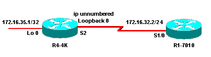
Reason 4: One Side Is Unnumbered and the Other Side Is Numbered
Consider the following network diagram as an example:
| R4-4K | R1-7010 |
|---|---|
interface Loopback0 ip address 172.16.35.1 255.255.255.255 interface Serial2 ip unnumbered Loopback0 router ospf 20 network 172.16.0.0 0.0.255.255 area 0 |
interface Loopback0 ip address 172.16.30.1 255.255.255.255 ! interface Serial1/0 ip address 172.16.32.2 255.255.255.0 clockrate 64000 router ospf 20 network 172.16.0.0 0.0.255.255 area 0 |
R4-4K(4)# show interface serial 2
Serial2 is up, line protocol is up
  Hardware is cxBus Serial
  Interface is unnumbered.  Using address of Loopback0 (172.16.35.1)

R1-7010(5)# show interface serial 1/0
Serial1/0 is up, line protocol is up
  Hardware is cxBus Serial
  Internet address is 172.16.32.2/24
The output above shows that R4-4K's Serial 2 interface is unnumbered to Loopback0, whereas R1-7010's Serial 1/0 is a numbered interface.
R4-4K(4)# show ip ospf interface serial 2
Serial2 is up, line protocol is up
  Internet Address 0.0.0.0/24, Area 0
  Process ID 20, Router ID 172.16.35.1, Network Type POINT_TO_POINT, Cost: 64
  Transmit Delay is 1 sec, State POINT_TO_POINT,
  Timer intervals configured, Hello 10, Dead 40, Wait 40, Retransmit 5
    Hello due in 00:00:02
  Neighbor Count is 1, Adjacent neighbor count is 1
    Adjacent with neighbor 172.16.32.2
  Suppress hello for 0 neighbor(s)

R1-7010(5)# show ip ospf interface serial 1/0
Serial1/0 is up, line protocol is up
  Internet Address 172.16.32.2/24, Area 0
  Process ID 20, Router ID 172.16.32.2, Network Type POINT_TO_POINT, Cost: 64
  Transmit Delay is 1 sec, State POINT_TO_POINT,
  Timer intervals configured, Hello 10, Dead 40, Wait 40, Retransmit 5
    Hello due in 00:00:02
  Neighbor Count is 1, Adjacent neighbor count is 1
    Adjacent with neighbor 172.16.33.1
  Suppress hello for 0 neighbor(s)
As you can see above, the network-type in both cases is point-to-point. The problem is that one side is unnumbered and the other side isn't, which creates a discrepancy in the database as shown below.
R4-4K(4)# show ip ospf database router 172.16.30.1

  OSPF Router with ID (172.16.35.1) (Process ID 20)
 Router Link States (Area 0)
 LS age: 202
     Options: (No TOS-capability, DC)
     LS Type: Router Links
     Link State ID: 172.16.30.1
     Advertising Router: 172.16.30.1
     LS Seq Number: 80000002
     Checksum: 0xC899
     Length: 60
     Number of Links: 3
 Link connected to: another Router (point-to-point)
     (Link ID) Neighboring Router ID: 172.16.35.1
     (Link Data) Router Interface address: 172.16.32.2
     Number of TOS metrics: 0
     TOS 0 Metrics: 64
 Link connected to: a Stub Network
     (Link ID) Network/subnet number: 172.16.32.0
     (Link Data) Network Mask: 255.255.255.0
     Number of TOS metrics: 0
     TOS 0 Metrics: 64
 Link connected to: a Stub Network
     (Link ID) Network/subnet number: 172.16.30.1
     (Link Data) Network Mask: 255.255.255.255
     Number of TOS metrics: 0
     TOS 0 Metrics: 1

     R4-4k(4)#

R1-7010(5)# show ip ospf database router 172.16.35.1

OSPF Router with ID (172.16.30.1) (Process ID 20)
     Router Link States (Area 0)
 Adv Router is not-reachable
     LS age: 396
     Options: (No TOS-capability, DC)
     LS Type: Router Links
     Link State ID: 172.16.35.1
     Advertising Router: 172.16.35.1
     LS Seq Number: 80000003
     Checksum: 0xBEA1
     Length: 48
     Number of Links: 2
 Link connected to: another Router (point-to-point)
     (Link ID) Neighboring Router ID: 172.16.30.1
     (Link Data) Router Interface address: 0.0.0.3


!--- In case of an unnumbered link we use MIB !--- II IfIndex value which usually starts
 with 0.


     Number of TOS metrics: 0
     TOS 0 Metrics: 64
 Link connected to: a Stub Network
     (Link ID) Network/subnet number: 172.16.35.1
     (Link Data) Network Mask: 255.255.255.255
     Number of TOS metrics: 0
     TOS 0 Metrics: 1

     R1-7010(5)#
You can see that R1-7010 is generating an LSA for this point-to-point link with the Link Data field containing its interface address, while R4-4K is generating the LSA for the same link with the Link Data field containing the MIBII IfIndex value. This creates a discrepancy in the link-state database, which means no routes are installed in the routing table.
R1-7010(5)# show ip route
172.16.0.0/16 is variably subnetted, 3 subnets, 2 masks
C       172.16.32.0/24 is directly connected, Serial1/0
C       172.16.30.1/32 is directly connected, Loopback0
Solution
To solve this problem, configure both routers' serial interfaces as either numbered or unnumbered. In this example we have numbered the serial 2 interface of router R4-4K.
R4-4K(4)# configure terminal
R4-4K(4)(config)# interface serial 2
R4-4K(4)(config-if)# no ip unnumbered loopback 0
R4-4K(4)(config-if)# ip address 172.16.32.1 255.255.255.0

R4-4K(4))# show ip ospf interface serial 2
Serial2 is up, line protocol is up
  Internet Address 172.16.32.1/24, Area 0
  Process ID 20, Router ID 172.16.33.1, Network Type POINT_TO_POINT, Cost: 64
  Transmit Delay is 1 sec, State POINT_TO_POINT,
  Timer intervals configured, Hello 10, Dead 40, Wait 40, Retransmit 5
    Hello due in 00:00:02
  Neighbor Count is 1, Adjacent neighbor count is 1
    Adjacent with neighbor 172.16.32.2
  Suppress hello for 0 neighbor(s)

R1-7010(5)# show ip route
172.16.0.0/16 is variably subnetted, 3 subnets, 2 masks
C       172.16.32.0/24 is directly connected, Serial1/0
O       172.16.33.1/32 [110/65] via 172.16.32.1, 00:03:08, Serial1/0
C       172.16.30.1/32 is directly connected, Loopback0
Reason 5: Broken PVC in Fully Meshed Frame Relay Environment
Consider this network diagram as an example:
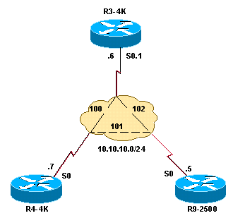
| R9-2500 |
|---|
interface Loopback0 ip address 50.50.50.50 255.255.255.255 ! interface Serial0 ip address 10.10.10.5 255.255.255.0 encapsulation frame-relay ip ospf network broadcast frame-relay map ip 10.10.10.6 102 broadcast frame-relay map ip 10.10.10.7 101 broadcast router ospf 10 network 10.10.10.0 0.0.0.255 area 0 network 50.50.50.0 0.0.0.255 area 0 |
| R4-4K |
|---|
interface Loopback0 ip address 70.70.70.70 255.255.255.255 ! interface Serial0 ip address 10.10.10.7 255.255.255.0 encapsulation frame-relay ip ospf network broadcast frame-relay map ip 10.10.10.5 101 broadcast frame-relay map ip 10.10.10.6 100 broadcast router ospf 10 network 10.10.10.0 0.0.0.255 area 0 network 70.70.70.0 0.0.0.255 area 0 |
| R3-4K |
|---|
interface Loopback0 ip address 60.60.60.60 255.255.255.255 ! interface Serial0 no ip address encapsulation frame-relay ! interface Serial0.1 multipoint ip address 10.10.10.6 255.255.255.0 ip ospf network broadcast frame-relay map ip 10.10.10.5 102 broadcast frame-relay map ip 10.10.10.7 100 broadcast ! router ospf 10 network 10.10.10.0 0.0.0.255 area 0 network 60.60.60.0 0.0.0.255 area 0 |
The broadcast model over Frame Relay works properly as long as the Frame Relay cloud is fully meshed. If any permanent virtual circuits (PVCs) are broken, it can create problems in the OSPF database, which in turn produces the Adv router not reachable message.
In this example, the PVC between R9-2500 and R4-4K is broken, and R9-2500 link to the designated router (DR) is broken. As a result, R9-2500 declares all LSAs from R3-4K (which is not a DR), as unreachable. As you can see, R9-2500 isn't generating a transit link for the serial interface attached to R3-4K; it is generating a stub link instead because as far as R9-2500 is concerned there is no DR on this link.
R9-2500(3)# show ip ospf database router

       OSPF Router with ID (50.50.50.50) (Process ID 10)
                Router Link States (Area 0)
  LS age: 148
  Options: (No TOS-capability, DC)
  LS Type: Router Links
  Link State ID: 50.50.50.50
  Advertising Router: 50.50.50.50
  LS Seq Number: 8000000B
  Checksum: 0x55A
  Length: 48
   Number of Links: 2

    Link connected to: a Stub Network
    (Link ID) Network/subnet number: 10.10.10.0
    (Link Data) Network Mask: 255.255.255.0
    Number of TOS metrics: 0
    TOS 0 Metrics: 64

    Link connected to: a Stub Network
    (Link ID) Network/subnet number: 50.50.50.50
    (Link Data) Network Mask: 255.255.255.255
    Number of TOS metrics: 0
    TOS 0 Metrics: 1

  Adv Router is not-reachable
  LS age: 1081
  Options: (No TOS-capability, DC)
  LS Type: Router Links
  Link State ID: 60.60.60.60
  Advertising Router: 60.60.60.60
  LS Seq Number: 80000006
  Checksum: 0x4F72
  Length: 48
   Number of Links: 2

    Link connected to: a Stub Network
    (Link ID) Network/subnet number: 60.60.60.60
    (Link Data) Network Mask: 255.255.255.255
    Number of TOS metrics: 0
    TOS 0 Metrics: 1

    Link connected to: a Transit Network
    (Link ID) Designated Router address: 10.10.10.7
    (Link Data) Router Interface address: 10.10.10.6
    Number of TOS metrics: 0
    TOS 0 Metrics: 64


  Adv Router is not-reachable
  LS age: 306
  Options: (No TOS-capability, DC)
  LS Type: Router Links
  Link State ID: 70.70.70.70
  Advertising Router: 70.70.70.70
  LS Seq Number: 80000007
  Checksum: 0xC185
  Length: 48
   Number of Links: 2

    Link connected to: a Stub Network
    (Link ID) Network/subnet number: 70.70.70.70
    (Link Data) Network Mask: 255.255.255.255
    Number of TOS metrics: 0
    TOS 0 Metrics: 1

    Link connected to: a Transit Network
    (Link ID) Designated Router address: 10.10.10.7
    (Link Data) Router Interface address: 10.10.10.7
    Number of TOS metrics: 0
    TOS 0 Metrics: 64
Refer to Problems with Running OSPF in NBMA and Broadcast Mode over Frame Relay for more detailed information about this problem.
Reason 6: Forwarding Address Known via an External Route
Consider this network diagram as an example:
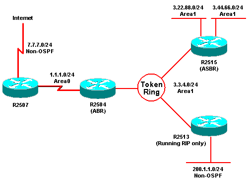
| R2507 |
|---|
interface Serial0
ip address 1.1.1.1 255.255.255.0

interface Serial1
ip address 7.7.7.1 255.255.255.0

router ospf 1
network 1.1.1.1 0.0.0.0 area 0
default- information originate metric 20

ip route 0.0.0.0 0.0.0.0 Serial1
|
| R2504 |
|---|
interface Serial0
ip address 1.1.1.2 255.255.255.0

interface TokenRing0
ip address 3.3.4.2 255.255.255.0

router ospf 1
network 1.1.1.0 0.0.0.255 area 0
network 3.0.0.0 0.255.255.255 area 1
area 1 range 3.0.0.0 255.0.0.0
|
| R2515 |
|---|
interface Serial1
ip address 4.4.4.3 255.255.255.0

interface TokenRing0
ip address 3.3.4.3 255.255.255.0

interface ethernet 0
ip address 3.44.66.3 255.255.255.0

interface ethernet 1
ip address 3.22.88.3 255.255.255.0

router ospf 1
redistribute rip metric 20 subnets
network 0.0.0.0 255.255.255.255 area 1

router rip
network 3.0.0.0
|
| R2513 |
|---|
interface TokenRing0
ip address 3.3.4.4 255.255.255.0

interface ethernet 0
ip address 200.1.1.4 255.255.255.0

router rip
network 3.0.0.0
network 200.1.1.0
|
R2507# show ip ospf data external 200.1.1.0
       OSPF Router with ID (7.7.7.1) (Process ID 1)
       Type- 5 AS External Link States
       LS age: 72
       Options: (No TOS- capability, DC)
       LS Type: AS External Link
       Link State ID: 200.1.1.0 (External Network Number )
       Advertising Router: 3.44.66.3
       LS Seq Number: 80000001
       Checksum: 0xF161
       Length: 36
       Network Mask: /24
                   Metric Type: 2 (Larger than any link state path)
                   TOS: 0
                   Metric: 20
                   Forward Address: 3.3.4.4
                   External Route Tag: 0
R2507 has 200.1.1.0/24 in its database but it hasn't installed it in the routing table because 3.3.4.4 is learned via an OSPF external route.
R2507# show ip route 3.3.4.4
       Routing entry for 3.3.4.0/ 24
       Known via "ospf 1", distance 110, metric 20,type extern 2, forward metric 70
       Redistributing via ospf 1
       Last update from 1.1.1.2 on Serial0, 00: 00: 40 ago
       Routing Descriptor Blocks:
       * 1.1.1.2, from 3.44.66.3, 00: 00: 40 ago, via Serial0
          Route metric is 20, traffic share count is 1
Note: With the fix of Cisco bug ID CSCdp72526 (registered customers only) , OSPF does not generate a type-5 link-state advertisement (LSA) of an overlapped external network; therefore, R2507 will only have a summary intra-area route of 3.0.0.0/8. Then, R2507 will install 200.1.1.0/24 as the forwarding address and it will be reachable via intra-area route 3.0.0.0/8, thus in compliance with RFC 2328.
After the fix of above mentioned bug, output will look like the following:
R2507# show ip route 3.3.4.4
      Routing entry for 3.0.0.0/8
      Known via "ospf 1", distance 110, metric 74, type inter area
      Last update from 1.1.1.2 on Serial0, 00:19:20 ago
      Routing Descriptor Blocks:
      * 1.1.1.2, from 3.3.4.2, 00:19:20 ago, via Serial0


R2507# show ip route
      Codes: C - connected, S - static, R - RIP, M - mobile, B - BGP
      D - EIGRP, EX - EIGRP external, O - OSPF, IA - OSPF inter area
      N1 - OSPF NSSA external type 1, N2 - OSPF NSSA external type 2
      E1 - OSPF external type 1, E2 - OSPF external type 2
      i - IS-IS, su - IS-IS summary, L1 - IS-IS level-1, L2 - IS-IS level-2
      ia - IS-IS inter area, * - candidate default, U - per-user static route
      o - ODR, P - periodic downloaded static route

Gateway of last resort is not set

1.0.0.0/24 is subnetted, 1 subnets
    C 1.1.1.0 is directly connected, Serial0
    O IA 3.0.0.0/8 [110/74] via 1.1.1.2, 00:30:18, Serial0
    O E2 200.1.1.0/24 [110/20] via 1.1.1.2, 00:22:58, Serial0
    Route metric is 74, traffic share count is 1

R2507#
If the forwarding address is also known via an external route, OSPF doesn't install that route in the routing table. For more detailed information about this problem, see Common Routing Problem with OSPF Forwarding Address.
Reason 7: Distribute List Is Blocking the Routes
Let's use the following network diagram as an example:
| R4-4K | R1-7010 |
|---|---|
interface Loopback0 ip address 172.16.33.1 255.255.255.255 interface Serial2 ip address 172.16.32.1 255.255.255.0 router ospf 20 network 172.16.0.0 0.0.255.255 area 0 |
interface Loopback0 ip address 172.16.30.1 255.255.255.255 ! interface Serial1/0 ip address 172.16.32.2 255.255.255.0 clockrate 64000 router ospf 20 network 172.16.0.0 0.0.255.255 area 0 distribute-list 1 in ! access-list 1 permit 172.16.32.0. 0.0.0.255 |
As you can see above, R1-7010 has the distribute-list command configured and it's only allowing the 172.16.32.0/24 address range to be installed in the routing table. In link-state protocols you can not really filter an LSA with the distribute-list command. The LSA will still be in the database; however the LSA will not be installed in the routing table.
R1-7010(5)# show ip ospf database router 172.16.33.1

  LS age: 357
  Options: (No TOS-capability, DC)
  LS Type: Router Links
  Link State ID: 172.16.33.1
  Advertising Router: 172.16.33.1
  LS Seq Number: 8000000A
  Checksum: 0xD4AA
  Length: 48
   Number of Links: 3

 Link connected to: another Router (point-to-point)
    (Link ID) Neighboring Router ID: 172.16.32.2
    (Link Data) Router Interface address: 172.16.32.1
    Number of TOS metrics: 0
    TOS 0 Metrics: 64
The distribute-list configuration command on R1-7010 is filtering the 172.16.33.1/32 network from being installed in the routing table.
R1-7010(5)# show ip route
172.16.0.0/16 is variably subnetted, 3 subnets, 2 masks
C       172.16.32.0/24 is directly connected, Serial1/0
C       172.16.30.1/32 is directly connected, Loopback0
Solution
To solve this problem, configure R1-7010 and allow 172.16.33.0/24 in the access control list (ACL) so this network gets installed in the routing table.
R1-7010(5)# configure terminal
R1-7010(5)(config)# access-list 1 permit 172.16.33.0 0.0.0.255
R1-7010(5)(config)# end

R1-7010(5)# show ip access-list 1
Standard IP access list 1
    permit 172.16.32.0, wildcard bits 0.0.0.255
    permit 172.16.33.0, wildcard bits 0.0.0.255

R1-7010(5)# show ip route
172.16.0.0/16 is variably subnetted, 3 subnets, 2 masks
C       172.16.32.0/24 is directly connected, Serial1/0
O       172.16.33.1/32 [110/65] via 172.16.32.1, 00:00:08, Serial1/0
C       172.16.30.1/32 is directly connected, Loopback0