Introduction
There are seven transmission modes in Release 8:
-
Single antenna port, port 0
-
Transmit diversity
-
Open-loop spatial multiplexing,large-delay Cyclic Delay Diversity (CDD)
-
Closed-loop spatial multiplexing
-
Multi-user MIMO
-
Codebook based beamforming (closed-loop spatial multiplexing using a single transmission layer)
-
UE-specific beamforming (single antenna port, port 5)
In transmission mode 7, UE-specific beamforming, arbitrary beamforming is applied and the User Equipment (UE) is not notified of the precoding matrix used, therefore the UE needs to estimate the channel including the effect of beamforming. As the UE requires only the UE specific reference signal for demodulation of the Physical Downlink Shared Channel (PDSCH), the data transmission for the UE appears to have been received from only one transmit antenna, therefore, this transmission mode is described as "single-antenna port, port 5".
Transmissions in this scheme are made on a single layer with a single reference signal and can be beamformed onto any number of transmission antennas using any appropriately dimensioned beamforming vector; the choice of the number of transmission antennas and beamforming vector values are not specified in the standard.
Release 10 allows for transmission of up to 8 layers on antenna ports 7-14 (TS36.213, Section 7.1.5B). Transmissions in this scheme are made on one or more layers with a reference signal (port) for each layer, and can be beamformed onto any number of transmission antennas using any appropriately-dimensioned beamforming matrix; the choice of the number of transmission antennas and beamforming matrix values are not specified in the standard.
System Processing
The following steps are used to create and receive a UE-specific beamformed PDSCH:
-
Create a Populated Transmit Resource Grid: A transmit grid is created with cell-specific channels but no PDSCH. The Populated Transmit Resource Grid containing the cell-specific channels of the RMC: Primary Synchronization Signal (PSS), Secondary Synchronization Signal (SSS), Reference Signal (RS), Physical Broadcast Channel (PBCH) and Physical Control Format Indicator Channel (PCFICH).
-
Set the Beamforming Vector: The beamforming vector indicating the complex gains to be applied to the single layer PDSCH transmission and its associated reference signal.
-
Create Transmit Waveform: OFDM modulate the transmit resource grid.
-
Noisy Propagation Channel Modeling:
-
Synchronization, Demodulation, and Channel Estimation: From the perspective of the receiver, the transmission made using UE-specific beamforming is effectively from a single antenna. Therefore the channel estimation and equalization attempts to estimate and equalize back to the original single transmission layer; Channel estimation is performed using the UE-specific reference signals;
-
PDSCH Reception: for UE-specific beamforming the receiver will carry out MMSE equalization across the receive antennas, to perform diversity combining.
Analysis
As can be seen from the figure, the system performs better when the beamforming vector has been matched to the channel response. Note that within the LTE specification, no assistance is provided in determining best beamforming vector. Possible approaches to determining the beamforming vector for example would be to exploit channel reciprocity in Time Division Duplex (TDD), or use angle of arrival estimation of the uplink signal in Frequency Division Duplex (FDD).
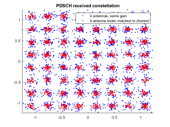
The red constellation exhibits a lower level of noise than the blue one, indicating better performance.
Below figures shows the Error Vector Magnitude (EVM) improvement achieved when using Precoding Matrix Indicator (PMI) feedback based on channel state information reference signal. A waveform with Physical Downlink Shared Channel (PDSCH) information is created and passed through a noisy fading channel. The received waveform is demodulated, resulting in a received resource grid for each receive antenna. An estimate of the channel is then used to decode the PDSCH, calculate the SNR and singular values of the channel and select an appropriate precoding matrix. The EVM of the received signal is calculated and used to estimate the effective channel SNR. This process is carried out with and without Channel State Information (CSI) and Reference Signal (RS) based PMI feedback to demonstrate the impact on performance.

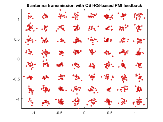
The second constellation(CSI-RS based PMI feedback) exhibits a lower level of noise than the first one, indicating better performance
Reference
1. MathWorks
2. TS 36.213