Introduction
The coded DCI messages for each control channel are multiplexed, scrambled, and undergo modulation, layer mapping, and precoding, as shown in the following figure.

Multiplexing
The blocks of coded bits for each control channel are multiplexed in order to create a block of data, as shown in the following figure.
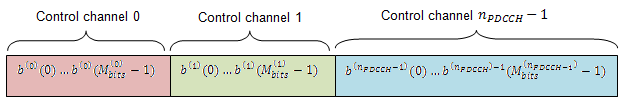
The variable Mibits is the number of bits in the ith control channel and nPDCCH is the number of control channels.
Matching PDCCHs to CCE Positions
If necessary, <NIL> elements are inserted in the block of bits prior to scrambling to ensure PDCCHs start at particular CCE positions and the length of the block of bits matches the amount of REGs not assigned to PCFICH or PHICH.
The PDCCH region consists of CCEs which could be allocated to a PDCCH. The configuration of how PDCCHs are mapped to CCEs is flexible.
Common and UE-specific PDCCHs are mapped to CCEs differently; each type has a specific set of search spaces associated with it. Each search space consists of a group of consecutive CCEs which could be allocated to a PDCCH called a PDCCH candidate. The CCE aggregation level is given by the PDCCH format and determines the number of PDCCH candidates in a search space. The number of candidates and size of the search space for each aggregation level is given in the following table.
| Search space, Sk(L) | Number of PDCCH candidates, M(L) | ||
|---|---|---|---|
| Type | Aggregation level, L | Size, in CCEs | |
| UE-specific | 1 | 6 | 6 |
| 2 | 12 | 6 | |
| 4 | 8 | 2 | |
| 8 | 16 | 2 | |
| Common | 4 | 16 | 4 |
| 8 | 16 | 2 | |
If the bandwidth is limited, not all candidates may be available because the PDCCH region is truncated.
A PDCCH can be mapped to any candidate within its suitable search space, as long as the allocated CCEs within the candidate do not overlap with a PDCCH already allocated. A simple example that shows the PDCCH candidates of two aggregation levels within a PDCCH region is shown in the following figure.
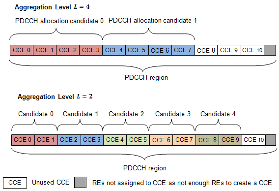
In this example, only 11 CCEs are available due to bandwidth constraints. The CCEs used to construct each PDCCH candidate are defined by the following equation.
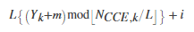
The preceding equation contains the following variables.
-
NCCE,k — number of CCEs in a subframe, k
-
m — number of PDCCH candidates in a given space, m=0,…,M(L)−1
-
L — aggregation level
-
i — an integer between 0 and L–1, i=0,…,L−1
When a common search space is used, Yk is 0. When a UE-specific search space is used, Yk is given by the following equation.
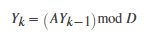
In the preceding equation, A is 39,827, D is 65,537, and Y–1 is the nonzero UE radio network temporary identifier.
Scrambling
This multiplexed block of bits undergoes a bit-wise exclusive-or (XOR) operation with a cell-specific scrambling sequence.
The scrambling sequence is pseudorandom, created using a length-31 Gold sequence generator and initialized using the slot number within the radio frame, ns, and the cell ID, NcellID, at the start of each subframe, as shown in the following equation.
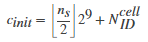
Scrambling serves the purpose of intercell interference rejection. When a UE descrambles a received bitstream with a known cell specific scrambling sequence, interference from other cells will be descrambled incorrectly, therefore only appearing as uncorrelated noise.
Layer Mapping
The complex symbols are mapped to one, two, or four layers depending on the number of transmit antennas used. The complex modulated input symbols, d(0)(i), are mapped onto v layers, x(0)(i),x(1)(i),…,x(v−1)(i).
If a single antenna port is used, only one layer is used. Therefore, x(0)(i)=d(0)(i).
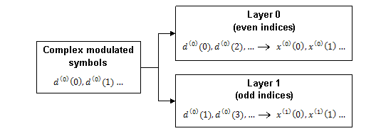
If transmitter diversity is used, the input symbols are mapped to layers based on the number of layers.
-
Two Layers — Even symbols are mapped to layer 0 and odd symbols are mapped to layer 1, as shown in the following figure.
-
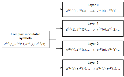
Four Layers — The input symbols are mapped to layers sequentially, as shown in the following figure.
Precoding
The precoder takes a block from the layer mapper, x(0)(i),x(1)(i),…,x(v−1)(i), and generates a sequence for each antenna port, y(p)(i). The variable p is the transmit antenna port number, and can assume values of {0}, {0,1}, or {0,1,2,3}.
For transmission over a single antenna port, no processing is carried out, as shown in the following equation.
y(p)(i)=x(0)(i)
Precoding for transmit diversity is available on two or four antenna ports.
Two Antenna Port Precoding. An Alamouti scheme is used for precoding, which defines the relationship between input and output as shown in the following equation.

In the Alamouti scheme, two consecutive symbols, x(0)(i) and x(1)(i), are transmitted in parallel using two antennas with the following mapping, where the asterisk symbol (*) denotes the complex conjugate operation.
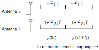
As any two columns in the precoding matrix are orthogonal, the two symbols, x(0)(i) and x(1)(i), can be separated at the UE.
Four Antenna Port Precoding. Precoding for the four antenna port case defines the relationship between the input and output as shown in the following equation.
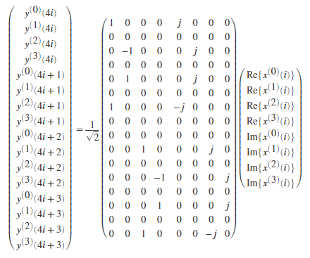
In this scheme, two consecutive symbols are transmitted in parallel in two symbol periods using four antennas with the following mapping, where the asterisk symbol (*) denotes the complex conjugate operation.

Mapping to Resource Elements
The complex valued symbols for each antenna are divided into quadruplets for mapping to resource elements. The sets of quadruplets then undergo permutation (interleaving) and cyclic shifting before being mapped to resource elements (REs) within resource-element groups (REGs).
Permutation. The blocks of quadruplets are interleaved as discussed in Sub-block Interleaver. However, instead of bits being interleaved, blocks of quadruplets are interleaved by substituting the term bit sequence with the term symbol-quadruplet sequence.
<NULL> symbols from the output of the interleaver are removed to form a sequence of interleaved quadruplets at each antenna, w(p)(i).
Cyclic Shifting. The interleaved sequence of quadruplets at each antenna is cyclically shifted, according to the following equation.

Mapping. The cyclic shifted symbol quadruplets are mapped to REGs that are not assigned to PCFICH or PHICH.
Each symbol-quadruplet is mapped to an unallocated REG in order, starting with the REG (k′=0,l′=0). Symbol quadruplet ‾‾w(p)(m′) maps to the REG m′. Then, the REG symbol index, l′, is incremented until all the REGs at subcarrier index k′=0 have been allocated. Next, the REG subcarrier index, k′, is incremented, and the process repeats. This mapping continues until all symbol quadruplets have been allocated REGs.
The mapping for an example resource grid is shown in the following figure.
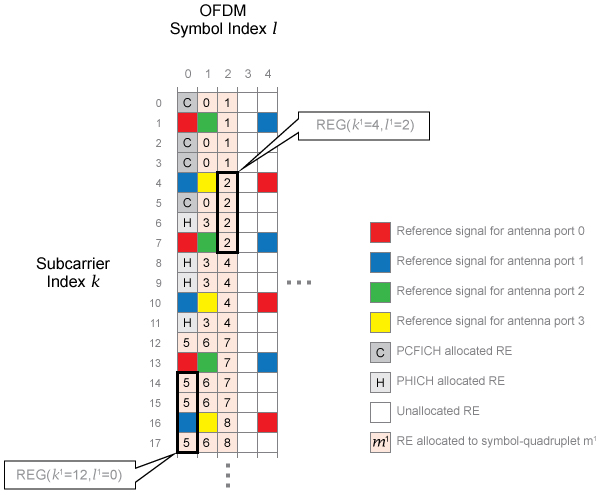
Four transmit antenna ports and a control region size of three OFDM symbols are used to create the grid. In this example, the REG (k′=0,l′=0) is allocated to PCFICH, so no symbol quadruplets are allocated to it. The symbol-quadruplets are first mapped to REG (k′=0,l′=1), followed by (k′=0,l′=2). Since there are no further REGs with k′=0, the next REG allocated is REG (k′=4,l′=2) because this REG has the lowest value of l′ not already allocated. This process repeats to allocate all the symbol quadruplets to REGs.
Reference,
1. MathWorks