程序示例代码
#include <GL/glut.h>
#include <stdlib.h>

void display(void)
{
/* clear all pixels  */
   glClear (GL_COLOR_BUFFER_BIT);

/* draw white polygon (rectangle) with corners at
 * (0.25, 0.25, 0.0) and (0.75, 0.75, 0.0)
 */
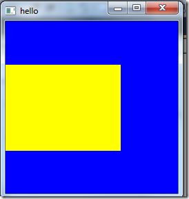
   glColor3f (1.0, 1.0, 0.0);
   glBegin(GL_POLYGON);
      glVertex3f (0.25, 0.25, 0.0);
      glVertex3f (0.75, 0.25, 0.0);
      glVertex3f (0.75, 0.75, 0.0);
      glVertex3f (0.25, 0.75, 0.0);
   glEnd();

   glFlush ();
}

void init (void)
{
/* select clearing color     */
   glClearColor (0.0, 0.0, 1.0, 0.0);

/* initialize viewing values  */
   glMatrixMode(GL_PROJECTION);
   glLoadIdentity();
   glOrtho(0.0, 1.0, 0.0, 1.0, -1.0, 1.0);
}

int main(int argc, char** argv)
{
   glutInit(&argc, argv);
   glutInitDisplayMode (GLUT_SINGLE | GLUT_RGB);
   glutInitWindowSize (250, 250);
   glutInitWindowPosition (100, 100);
   glutCreateWindow ("hello");
   init ();
   glutDisplayFunc(display);
   glutMainLoop();
   return 0;
}
以下为上面代码的示例的讲解
清除窗体
在第1节中讲到glClearColor用于清除颜色并重新设置新的颜色,在回调函数中glutDisplayFunc必须
以显示的方式设置窗体的背景颜色,这个函数为glClear ,GL_COLOR_BUFFER_BIT表示颜色缓冲区.
所以说每次在回调时,窗体是不断的在重绘的.
指定形状颜色
OpenGl绘制图形形状时,并不绘制颜色,而是在绘制形状之前指定好颜色如
glColor3f (1.0, 1.0, 0.0);即指定一个黄色,指定完毕后然后执行绘图
绘制一个基本的矩形
glBegin(GL_POLYGON);
   glVertex3f (0.25, 0.25, 0.0);
   glVertex3f (0.75, 0.25, 0.0);
   glVertex3f (0.75, 0.75, 0.0);
   glVertex3f (0.25, 0.75, 0.0);
glEnd();
以上看来绘制一个矩形也并不简单,GL_POLYGON表示绘制多边形,矩形正是4变形.
绘制开始前必须调用glBegin以通知绘制图形的类型,比如还可以绘制点,线等.
结束之后则要调用glEnd函数
glVertex3f 函数用于指定每个点的坐标顶点,由于是绘制2d图形,所以z坐标都为0
这里可以看到坐标有点奇怪,那么就要关注坐标系是如何定义的
定义坐标系
windows窗体默认以左上角为(0,0)点,然后以一个像素为基础来绘制图形,我们总是能知道窗体的大小,然后OpenGl则需要调用自身的函数来确定
glutReshapeFunc(void (*func)(int w, int h)) indicates what action should be taken when the window is resized.
如glutReshapeFunc(ChangeSize);
void ChangeSize(int w, int h)
    {
       // Set Viewport to window dimensions
    glViewport(0, 0, w, h);
    }
Defining the Viewport
To understand how the viewport definition is achieved, let’s look more carefully at the
ChangeSize function. It first calls glViewport with the new width and height of the
window. The glViewport function is defined as
void glViewport(GLint x, GLint y, GLsizei width, GLsizei height);
The x and y parameters specify the lower-left corner of the viewport within the window,
and the width and height parameters specify these dimensions in pixels. Usually, x and y
are both 0, but you can use viewports to render more than one drawing in different areas
of a window. The viewport defines the area within the window in actual screen coordinates
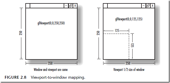
that OpenGL can use to draw in (see Figure 2.8). The current clipping volume is
then mapped to the new viewport. If you specify a viewport that is smaller than the
window coordinates, the rendering is scaled smaller, as you see in Figure 2.8.
Defining the Clipped Viewing Volume
The last requirement of our ChangeSize function is to redefine the clipping volume so that
the aspect ratio remains square. The aspect ratio is the ratio of the number of pixels along
a unit of length in the vertical direction to the number of pixels along the same unit of
length in the horizontal direction. In English, this just means the width of the window
divided by the height. An aspect ratio of 1.0 defines a square aspect ratio. An aspect ratio
of 0.5 specifies that for every two pixels in the horizontal direction for a unit of length,
there is one pixel in the vertical direction for the same unit of length.
If you specify a viewport that is not square and it is mapped to a square clipping volume,
the image will be distorted. For example, a viewport matching the window size and
dimensions but mapped to a square clipping volume would cause images to appear tall
and thin in tall and thin windows and wide and short in wide and short windows. In this
case, our square would appear square only when the window was sized to be a square.
In our example, an orthographic projection is used for the clipping volume. The OpenGL
command to create this projection is glOrtho:
void glOrtho(GLdouble left, GLdouble right, GLdouble bottom,
GLdouble top, GLdouble near, GLdouble far );
In 3D Cartesian space, the left and right values specify the minimum and maximum
coordinate value displayed along the x-axis; bottom and top are for the y-axis. The near
and far parameters are for the z-axis
我们可以用gluOrtho2D函数来修剪2维坐标系
如gluOrtho2D(0.0, 1.0, 0.0, 1.0);
即x轴的范围为0-1,y轴为0-1,然后我们重新看到之前矩形的坐标如0.25(不要以一个像素为1来理解,可以以百分比的方式来理解),如果以百分比来计算的话,那么无论宽度和高度范围,就可以永远将图形画在正中间
好比glViewport是一块画布的大小,而gluOrtho(修剪空间)则定义了画布的可视范围
如现在将x的可视范围改成0.25-1,那么矩形的左侧可视范围就没了
gluOrtho2D(0.25, 1.0, 0.0, 1.0);
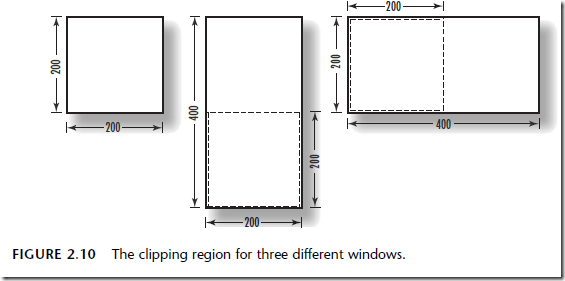
可以把不同的窗体修剪成相同高度和宽度的范围,如下图
这次主要理解坐标系的定义,还有两个函数没讲到


