Two ways to describe the Internet
1. A nuts-and-bolt description (hardware&software component)
The Internet is a computer network (of communication links and packet switches) that interconnects millions of computing devices(hosts/end systems) throughout the world.
Packets: When one end system has data to send to another end system the sending end system segments the data and add header bytes to each segment, the resulting packages of information are packets. Packets are sent through the network to the destination end system and reassembled into original data.
Packet switch: takes a packet arriving on one of its incoming communication links and forwards that packet on one of its outgoing communication links. (Exp: routers&link-layer switches)
Route/path: the sequence of communication links and packet switches traversed by a packet from the sending end system to the receiving end system.
ISP(Internet Service Providers): End system access the Internet through ISP(residential ISPs/corporate ISPs/university ISPs…). Each ISP is in itself a network of packet switches and communication links, providing work access to the end systems&Internet access(lower-tier ISPs need to interconnected through upper-tier ISPs).
IP(Internet Protocol): specifies the format of the packets that are sent and received among routers and end systems.
RFCs: IETF standard documents, define most protocols such as TCP/IP,HTTP,SMTP…
2. A service description
The Internet is an infrastructure that provides services to (distributed) applications.
Distributed application only runs on end system, each end system attached to the Internet provide the Internet API(Application Programming Interface) that specifies how an application running on the sending end system asks the Internet infrastructure to deliver data to a specific destination application on the receiving end system.
Network protocol: A protocol defines the format and the order of messages exchanged between 2 or more communicating entities, as well as the actions taken on the transmission and/or a message or other event.
End systems(hosts): The computers and other devices connected to the Internet, sometimes can be divided into 2 categories—clients and servers.
Client program & server program: a client program is a program running on one end system that requests and receives a service from a server program running on another end system.
P2P(peer-to-peer) applications: in which end systems interact and run programs that perform both client and server functions.
Access networks
Access networks: the physical link(s) that connect an end system to its edge router (the first router on a path from the end system to any other distant end system).
Access networks can be loosely classified into 3 categories: Residential access, Company access and Wireless access.
Residential access(use dial-up modem, DSL, HFC)/Company access(use LAN, Ethernet) connects an end system to the edge router.
Wireless access: 2 types. a. wireless LAN(short radius) b. wide-area wireless access networks(long radius).
Physical medium: 2 categories, a. guided media(waves are guided along a solid medium) b. unguided media(waves propagate in the atmosphere and outer space such as wireless LAN).
Circuit Switching & Packet Switching
Two fundamental approaches to moving data through a network of links and switches:
a. Circuit switching: (exp: telephone network)
Hosts are each directly connected to one of the switches;
switches are interconnected by links;
Each link consists of n circuits (implemented with TDM or FDM), can support n simultaneous connections;
When 2 hosts want to communicate, establish an end-to-end connection;
When sending messages, first reserve one circuit on each of the links.
Pros: Resources are reserved, guaranteed rate. (suitable for real-time services)
Cons: idle resources are wasted during silent period, complicated.
FDM: The link dedicates a frequency band to each connection for the duration of the connection (Allocate specific frequency band to different connections). The width of the band is called bandwidth.
TDM: When the network establishes a connection across a link, the network dedicates one time slot in every frame to this connection, these slots are dedicated for the sole use of that connection. (One slot for use in every frame for that connection).
Transmission rate of a circuit for TDM(bps) = frames rate(frames per second) * number of bits in a slot(bits)
Cal:
How long it takes to send a file of 640,000 bits from Host A to Host over a circuit-switched network?
All links use TDM with 24 slots, bit rate = 1.536Mbps, 0.5s to establish an end-to-end circuit before transmission.
Ans:
Each circuit has a transmission rate of (1.536Mbps)/24 = 64kbps;
Takes (640,000bits)/(64kbps)=10s to transmit;
Add the establish time to get in total (10+0.5)=10.5 s to send the file.
Note: The transmission time is independent of the number of links, remain the same no matter the end-to-end circuit passed through 1 links or 100 links.
b. Packet switching: (exp: Internet)
The source breaks long messages into packets;
Between source and destination, packets travel through communication links and packet switches (Each packet switch has multiple links attached to it);
Packets are transmitted over each communication link at a rate equal to the full transmission rate of the link.
Resources are not reserved, no guarantee, best effort, may have to wait.
Pros: better sharing of bandwidth, simpler, more efficient.
Cons: Not suitable for real-time service.
packet switches: a. routers b. link-layer switches
Store-and-forward transmission: (Used by most packet switches) The switch must receive the entire packet before it can begin to transmit the first bit of the packet onto the outbound link, thus introduce a store-and-forward delay at the input to each link along the packet’s route.
Cal:
How long it takes to send a packet of L bits from one host to another host across a packet-switched network?
Q links between the two hosts, each of rate R bps, assume that this is the only packet in the network.
Ans:
First transmit onto the first link from Host A, takes L/R seconds;
Then transmit on remaining Q-1 links, store and forward Q-1 times, each time with a store-and-forward delay of L/R;
Thus the total delay is QL/R.
Queueing delays: A packet switch has an output buffer (output queue) for each attached link. If the link is busy, the arriving packet must wait in the output buffer, thus introduce a buffer queueing delay. If the buffer is full, packet loss will occur.
Difference:
Circuit switching pre-allocates use of transmission link regardless of demand (with allocated but unneeded link time going unused);
Packet switching allocates link use on demand, link transmission capacity will be shared on a packet-by-packet basis only among those users who have packets that need to be transmitted over the link. (on-demand sharing of resources, a.k.a. statistical multiplexing of resources).
ISP
Access networks situated at the edge of the Internet are connected to the rest of the Internet through a tired hierarchy of ISPs.
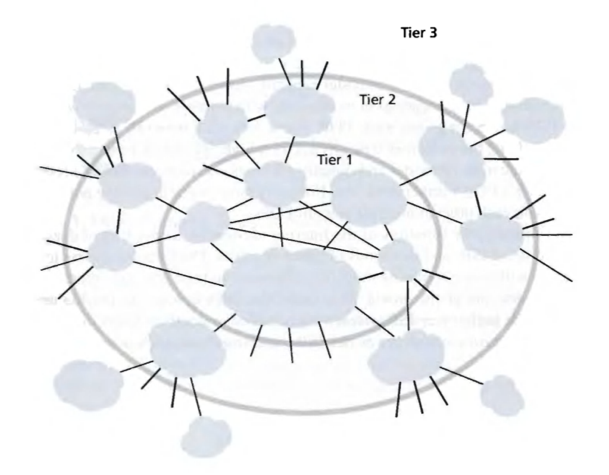
Tier-1 ISPs (a.k.a. Internet backbone networks) are at the very top of the hierarchy.
Directly connected to each of the other tier-1 ISPs;
Connected to a large number of tier-2 ISPs and other customer networks;
International in coverage, high rate.
(e.g. Sprint, Verizon, AT&T, NTT, Level3, Qwest.)
Tier-2 ISPs
have regional or national coverage;
A tier-2 ISP connects to only a few of the tier-1 ISPs, may also connect directly to other tier-2 networks;
A tier-2 ISP is a customer of the tier-1 ISP to which it is connected, and the tier-1 is a provider to its customer.
Access ISPs are at the bottom of the hierarchy. (e.g. residential cable, DSL networks, dial-up access networks, wireless access networks, company and university ISPs.)
Users and content providers are customers of lower-tier ISPs, and lower-tier ISPs are customers of higher-tier ISPs.
When 2 ISPs are directly connected to each other, they are said to peer with each other.
Points of Presence (POPs): within an ISP’s network, the points at which the ISP connects to other ISPs.
A POP is a group of one or more routers in the ISP’s network at which routers in other ISPs or in the networks belonging to the ISP’s customers can connect.
Delay, Loss and throughput in packet-switched networks
The most important delays in packet-switched network: nodal processing delay, queuing delay, transmission delay, and propagation delay; together accumulate to give a total nodal delay (The delay at a single router).
dnodal = dproc + dqueue + dtrans + dprop
Processing delay: Time to examine the packet’s header and determine where to direct the packet + time to check for bit-level errors in the packet.
Queuing delay: Time to wait to be transmitted onto the link. (depend on the number of earlier-arriving packets that are queued and waiting for transmission across the link.)
Transmission delay / Store-and forward delay: The time required to push all of the packet’s bits into the link.
The length of the packet = L bits, the transmission rate of the link = R bits/sec. (e.g. for a 10Mbps Ethernet link, R=10Mbps.)
Transmission delay = L/R.
Propagation delay: The time to propagate from the beginning of the link to the router (on the other side of the link).
The distance between router A and router B = d, the propagation speed of the link = s.
The propagation delay = d/s.
Comparing Transmission and propagation delay
The transmission delay is the time required for the router to push out the packet, it is a function of the packet’s length and the transmission rate of the link;
The propagation delay is the time it takes a bit to propagate from one router to the next, it is a function of the distance between the 2 routers.
Queuing delay & Traffic intensity & packet loss
The average rate at which packets arrive at the queue = a (in packets/sec), the transmission rate = R (in bits/sec), all packets consist of L bits;
Traffic intensity = La/R. (should be no greater than 1)
If La/R>1, the queue will tend to increase without bound and the queueing delay will approach infinity.
If La/R=1, the queueing delay are impacted by the nature of the arriving traffic impacts (arrive periodically or in bursts?)
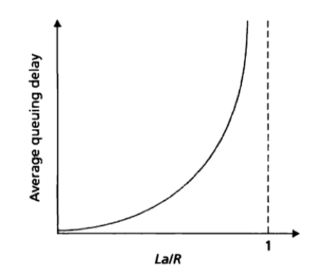
As La/R approaches 1, the average queuing length gets larger and larger.
Because in reality the queue capacity is finite, packet delays do not really approach infinity as La/R approaches 1. So a packet can arrive to find a full queue and will be lost.
Throughput
Consider transferring a large file from Host A to Host B across a computer network, the file consists of F bits and the transfer takes T seconds for Host B to receive all bits.
The Instantaneous throughput: The rate at an instant of time at which Host B is receiving the file.
The average throughput: F/T bits/sec.
Consider a network with N links between the server and the client, with the transmission rates of the N links being R1, R2, …, RN.
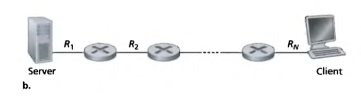
The throughput for a file transfer from server to client is min{R1, R2, …, RN}, i.e. the transmission rate of the bottleneck link.
More generally, the throughput depends not only on the transmission rates of the link along the path, but also on the intervening traffic.
Protocol layers and their service models
Protocol layering
Protocols – and the network hardware and software that implement the protocols – are organized in layers, each protocol belongs to one of the layers.
Service model of a layer: The services that a layer offers to the layer above. Each layer provides its service by (1) performing certain action within that layer; (2) using the services of the layer directly below it.
Pros: provides a structured way to discuss system components; modularity makes it easier to update system component.
Cons: One layer may duplicate lower-layer functionality; functionality at one layer may need information that is present only in another layer, this violates the goal of separation of layers.
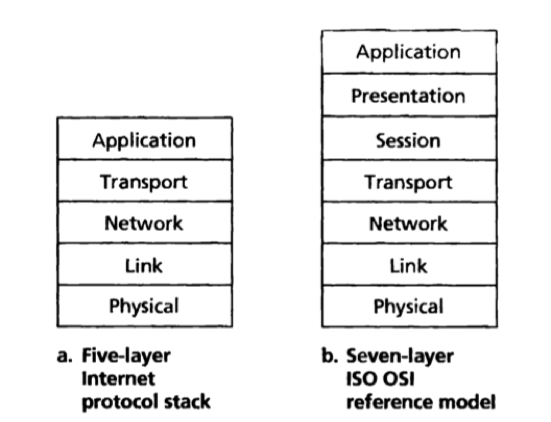
The protocol stack: The protocols of the various layers taken together.
The internet protocol stack consists of 5 layers: the physical, link, network, transport, and application layers.
Application layer
Message: An application-layer packet.
The application layer is where network application and their application-layer protocols reside.
Protocols in the Internet’s application layer: HTTP, SMTP, FTP, DNS, … .
An application-layer protocol is distributed over multiple end systems, with the application in one end system using the protocol to exchange messages with the application in another end system.
Transport layer
Segment: A transport-layer packet.
The transport layer transports application-layer message between application endpoints.
Protocols in the Internet’s transport layer: TCP and UDP.
Network layer
Datagram: A network-layer packet.
The network layer receives a transport-layer segment and a destination address passed from the transport-layer protocol in a source host, moves the datagram from one host to another, and deliver the segment to the transport layer in the destination host.
Protocols in the Internet’s network layer: IP Protocol (only one), routing protocols (numerous).
Link layer
Frame: An link-layer packet.
At each node, the link layer receives a datagram passed down from the network layer, delivers the frame from one node to the next node in the route, and passes the datagram up to the network layer in the next node.
Protocols in the Internet’s link layer: Ethernet, WiFi, PPP, … .
A datagram may be handled by different link-layer protocols at different links along its route.
Physical layer
The physical layer moves the individual bits within the frame from one node to the next.
The protocols in physical layer are link dependent, and depends on the actual transmission medium of the link.
The OSI Model
OSI model: Open System Interconnection model. (Consists of 7 layers.)
The presentation layer: to provide service that allow communicating applications to interpret the meaning of data exchange, these services include data compression, data encryption and data description.
The session layer: to provide for delimiting and synchronization of data exchange.
Messages, segments, datagrams and frames
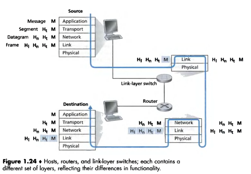
Encapsulation:
At the sending host, an application-layer message is passed to the transport layer;
The transport layer takes the message and adds transport-layer header information, creating a transport-layer segment;
The network layer takes the segment and adds network-layer header information, creating a network-layer datagram;
The link layer takes the datagram and adds link-layer header information, creating a link-layer frame.
At each layer, a packet has 2 types of field: header field and a payload field (i.e. a packet from the layer above).
Networks under attack
Malware: stuff that can enter and infect devices and do devious things. (Much of the malware is self-replicating.)
Botnet: A network of thousands of similarly compromised devices, controlled and leveraged fro spam e-mail distribution or distributed denial-of-service attacks against targeted hosts.
Viruses: Malware that require some form of user interaction to infect the user’s device.
Worms: Malware that can enter a device without any explicit user interaction.
Trojan horse: Malware that is a hidden part of some otherwise useful software.
Denial-of-service (DoS) attack: A broad class of security threats that renders a network, host , or other piece of infrastructure unusable by legitimate users.
Most Internet Dos attacks fall into one of 3 categories:
a) Vulnerability attack: sends a few well-crafted message to a vulnerable application or operating system running on a targeted host. if the right sequence of packet is sent to a vulnerable application or operating system, the service can stop or the host can crash.
b) Bandwidth flooding: sends a deluge of packets to the targeted host so that the target’s access link becomes clogged, preventing legitimate packets from reaching the server.
c) Connection flooding: establishes a large number of half-open or fully open TCP connections at the target host, and the host becomes bogged down and stops accepting legitimate connections.
Distributed DoS (DDoS) attack: controls multiple sources and has each source blast traffic at the target, much harder to detect and defend against than a DoS attack from a single host.
Packet sniffer: A passive receiver that records a copy of every packet that flies by. (Can be employed in wireless or wired environments.)
Solution: cryptography.
IP spoofing: to inject packets into the internet with a false source address, a way in which one user can masquerade as another user.
solution: end-point authentication.
Man-in-the-middle attack: The bad guy (could be a compromised router or a software module residing on one of the end hosts at a lower layer in the protocol stack), inserted into the communication path between 2 communicating entities, not only has the ability to sniff all packets that pass between the 2 entities but can also inject, modify, or delete packets.
A man-in-the-middle attack can compromise the integrity of the data sent between the 2 entities.