一、下载VITIS-AI的仓库
单独git clone很慢,因此先将其导入到gitee平台,再执行clone
1. Import VITIS-AI github repo into gitee repo
2. Git clone repo from gitee
二、安装Docker
参考:https://docs.docker.com/engine/install/ubuntu/,并执行:
1. “Install using the repository”的全部步骤
2. “Install Docker Engine”的 sudo apt-get install docker-ce docker-ce-cli containerd.io
三、修改docker的配置文件
使用国内镜像(阿里云、网易云....)。
sudo gedit /etc/docker/daemon.json
{
"registry-mirrors": [
"https://kfwkfulq.mirror.aliyuncs.com",
"https://2lqq34jg.mirror.aliyuncs.com",
"https://pee6w651.mirror.aliyuncs.com",
"https://registry.docker-cn.com",
"http://hub-mirror.c.163.com"
]
}
参考:https://blog.oioweb.cn/index.php/archives/1347.html四、加载重启docker
$ sudo systemctl daemon-reload
$ sudo systemctl restart docker
五、从docker中下载文件
sudo docker pull xilinx/vitis-ai:latest
六、Run docker
打开从gitee下载的Vitis-AI文件路径
cd Vitis-AI
sudo ./docker_run.sh xilinx/vitis-ai:latest
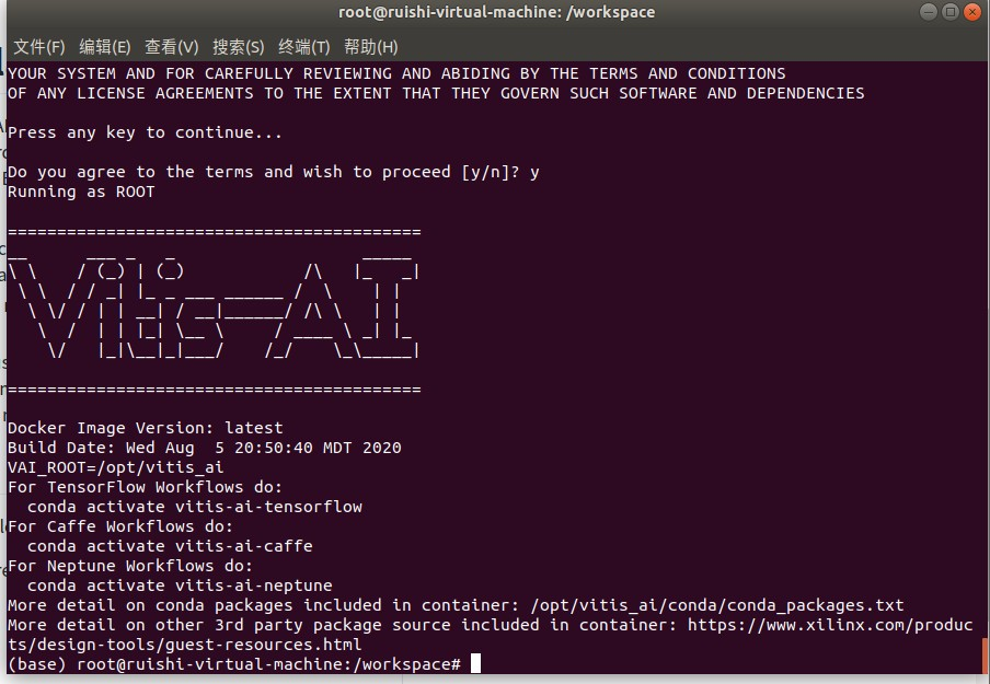
按照提示操作知道出现logo“VITIS—AI”表示安装成功,输入exit退出。
七、下载VITIS-AI tutorial
该仓库的master分支只有一个Readme.md文件。其他的例子在其他份分支上:
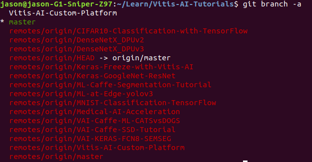
如果想切换到其他分支(比如Vitis-AI-Custom-Platform),则执行git checkout Vitis-AI-Custom-Platform。
VitisAI(Ultra96v2)平台教程(GitHub开源 https://github.com/Xilinx/Vitis-AI-Tutorials/tree/Vitis-AI-Custom-Platform)
一、阅读Vitis-AI-Tutorial文件中
/files/tutorials/1-Building-a-Vitis-Ultra96V2-and-MIPI-platform.md
1、 首先在Vivado中创建MIPI项目,安装Petalinux工具。其次在ultra96上启动硬件和软件镜像来观察MIPI视频。
1.1、将Vitis-AI-Tutorial文件夹中 reference-files/vivado/sources的sources文件复制到 build/vivado 路径下。
1.2、打开Vivado2019.2(后综合发现vivado2019.2版本不支持mipi IP核,vivado2020.1版本方可支持)
1.3、在build/vivado创建一个新的项目,将其命名为‘ultra96v2_mipi’-----选择RTL项目-----do not specify sources-----Boards-----Ultra96v2-----Finish。
1.4、在Tcl控制台窗口打开sources路径。
1.5、Use the Tcl Console to call `source ./sources/u96v2_mipi.tcl`.
1.6、在Sources标签中右键`u96v2_mipi.bd`然后‘Create HDL Wrapper’。
1.7、添加xdc文件,从 `build/vivado/sources` 复制`cnst.xdc`文件到项目约束文件中。
2、为使用Vitis开发工具设计做准备
打开Vivado工程修改硬件设计为软件加速做准备。
3、配置平台接口
3.1、添加ZYNQUltraSCALE IP核,打开“Window”目录选择“Platform Interfaces”,
使能下列三个PS从接口,和一个master主接口(如果不做使能配置,直接在ZYNQ GUI界面勾选应该是可以的)
* S_AXI_HP0_FPD
* S_AXI_HP1_FPD
* S_AXI_HP2_FPD
* HPM0_FPD
Platform Interfaces**Options**选项中将三个slave接口的“stpg”值依次设置为: `HP0`, `HP1`, and `HP2`
4、指定平台时钟
4.1. Double-click the **clk_wiz_0 IP**, and make the following changes in the Output Clocks tab:`[clk_out3=150MHz], [clk_out4=300MHz], [Matched routing selected on clk_out3/4], [Reset Type = Active Low]`
4.2. Right-click the block design, select **Add IP**, and add a processor system reset IP for each of the new clocks.
4.3 Name the new clocks, `proc_sys_reset_dynamic_1` and `proc_sys_reset_dynamic_2`.
4.4 Connect the `clk_out3` and `clk_out4` outputs of `clk_wiz_0` block to `proc_sys_reset_dynamic_1` and `proc_sys_reset_dynamic_2` `slowest_sync_clk` inputs, respectively.
4.5 Connect the `ext_reset_in`(proc_sys_rest IP的接口) to `pl_resetn0` on the MPSoC block.
4.6 Connect the "locked" output of the Clock Wizard to the `dcm_locked` port of the processor reset blocks.
4.7 确保每个‘proc_sys_reset` 模块的`ext_reset_in` 与`pl_resetn0` 连接。
4.8 In the Platform Interfaces tab, enable `clk_out3` and `clk_out4` of the `clk_wiz_0` instance.
4.9 Set the slower clock (in this case, `clk_out3`) as the default. `clk_out3` should have its id set to 0, and `clk_out4` should have its id set to 1.
4.10 Make sure the `proc_sys_reset` block listed in each window is set to the instance that is connected to that clock. Check the properties/options window when each clock is selected in platform interfaces, and verify the proc_sys_reset parameter matches.
5、使能中断
5.1、添加IP核AXI Interrupt Controller命名为“axi_intc_0“。双击IP核进行配置,修改为”Edge or Level”和”Single”,点选OK。
5.2、添加IP核Concat命名为”xlconcat_interrup_0”,配置IP端口数为8.
5.3、添加IP核Constant,配置值为’0’,连接到interrupt controller,命名为”xlconstant_gnd”。
5.4、”Run Connection Automation”,自动连接将AXI Interrupt Controller的从接口连接到PS的”HPM0_LPD”主接口上。将”clk_out1(200MHz)”选择为所有模块的时钟资源。
5.5、将”interrupt controller”的输入与”concat”模块输出连接。
5.6、将”constant”模块的输出与”concat”模块的第一个输入连接。then each subsequent concat input to this net。
5.7、将”interrupt comtroller”模块的输出与PS模块的”pl_ps_irq0”连接。
6、生成XSA文件
综合、布局布线、生成bit流,导出自定制硬件平台设计;可通过TCL指令或者点选界面执行。
source ./sources/xsa.tcl
注意:Vivado工程路径不要太长,此时如果将sources文件夹放在路径 ~build/vivado下并且执行sources下的xsa脚本,生成的.xsa文件会存放在与~build/hw_platform文件夹下面。
创建软件平台
The software platform requires several changes to the default Petalinux template. Begin by configuring the project to include a meta-layer, which builds in all necessary support for the MIPI mezzanine card and pipeline. Then, finish by adding the necessary Xilinx Runtime (XRT) components into the design.
7、安装petalinux工具在ubuntu上
# 安装步骤
7.1 运行 `bash pre_install.sh`
7.2 运行 `bash tftp.sh`
7.3 运行
```bash
mkdir /tools/Xilinx/
sudo chown 你的用户名 /tools/Xilinx
```
7.4 运行 `./petalinux-v2020.1-final-installer.run -d /tools/Xilinx`
7.5 zyp使用:source /tools/Xilinx/settings.sh 注:每次使用petalinux工具时都要执行settings.sh;
8、定制Petalinux项目(createàconfigàbuildàboot)
8.1、在’build/’路径下打开备用的petalinux工程。
8.2、创建新的带有zynqMP模板的petalinux工程
‘petalinux-create -n petalinux --template zynqMP -t project’
8.3、从`reference-files/ petalinux’下复制文件夹`meta-ultra96v2mipi`,粘贴到’build/ petalinux/ components’路径下。
8.4、更新Petalinux工程(xsa文件)并且打开初始化配置菜单。
‘petalinux-config --get-hw-description=../hw_platform`
注意:hw_platform文件夹路径问题。
若出现报错:将ultra96 路径下的layer.conf文件中 thud 改成 zeus.
8.5、主菜单中选择”Subsystem AUTO settings”和目录下的”Serial Settings”。修改’psu_uart_1’作为primary(原默认psu_uart_0)。
8.6、主菜单中选择”DTG Settings”并且设置命名为’avnet-ultra96-rev1’(原来默认template)。
8.7、主菜单中选择”Yocto Settings” à”User Layers”并且添加
${PROOT}/components/meta-ultra96v2mipi 作为用户第一层,然后退出初始化配置菜单。
8.8、添加平台XRT驱动,添加recipes通过拷贝`reference-files/ petalinux`路径下的`recipes-xrt`文件到`build/ petalinux/ project-spec/ meta-user`路径下。
8.9、添加recipes”自动运行”的脚本,保证在root后可自动运行recipes,拷贝路径’reference-files/petalinux/autostart’ autostart目录到’build/ petalinux/ project-spec/ meta-user/ recipes-apps’路径下。
8.10、将上述recipes添加到petalinux镜像配置中,在[build/ petalinux/ project-spec/ meta-user/ conf/ user-rootfsconfig]文件中内容添加 [reference-files/ petalinux/ plnxrfscfg.txt]文件内容。
8.11、打开Petalinux的根文件系统配置界面去使能上述的recipes
`petalinux-config -c rootfs`然后添加在"User Packages" and "Apps" 的子目录下的`user-rootfsconfig`文件。
8.12、在rootfs配置下,under the Petalinux Packge Groups,使能如下选项:
gstreamer、matchbox、opencv、v4lutils、x11。
8.13、退出rootfs配置菜单。
9、修改Linux设备树
9.1、打开文件`build/ petalinux/ project-spec/ meta-user/ recipes-bsp/ device-tree/ files/ system-user.dtsi`。用`reference-files/ petalinux/ dtfrag.txt`内容替换打开的内容。
离线编译petalinux:官网下载aarch64 sstate-cache和downloads文件并解压,存放路径不要出现空格字符,否则后期编译会出现错误。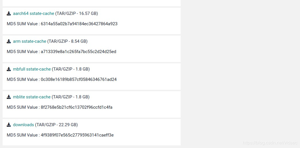
配置sstate
在petalinux工程路径下输入petalinux-config命令进入配置界面

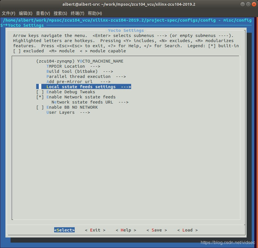
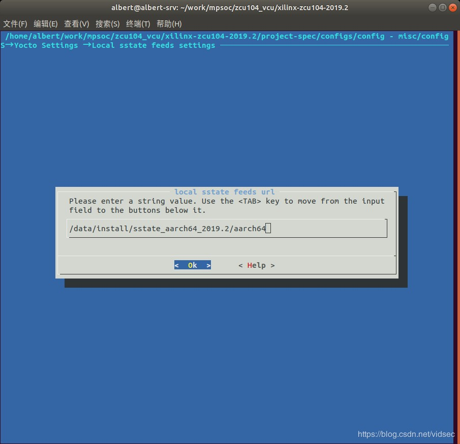
1.运行petalinux-config报错:

将下面两个文件中的thud修改为zeus

2.petalinux-build编译报错
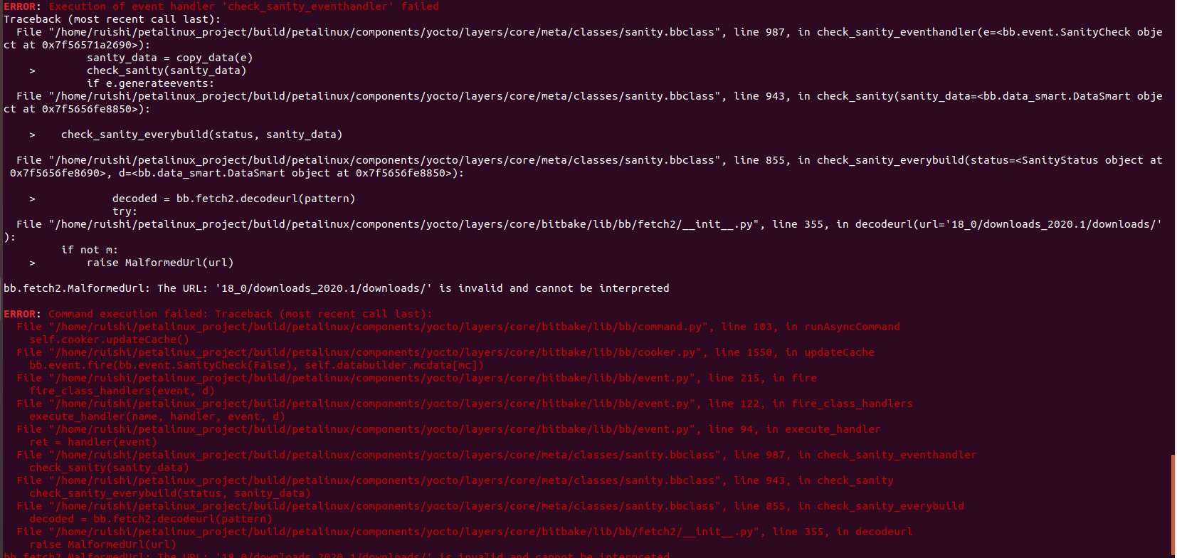
解决:aarch64 sstate-cache和downloads文件存放的路径有空格字符,修改路径信息,编译通过。
配置本地downloads
打开文件 project-spec/meta-user/conf/petalinuxbsp.conf进行如下配置,文件末尾添加6行,注意替换自己的实际目录

petalinux编译: $petalinux-build
petalinux-build编译报错

注:查询资料这些错误是因为Ubuntu磁盘空间不足导致,重做Ubuntu系统磁盘空间留300G
重新运行petalinux工具 source /tools/Xilinx/settings.sh
petalinux-build编译报错:

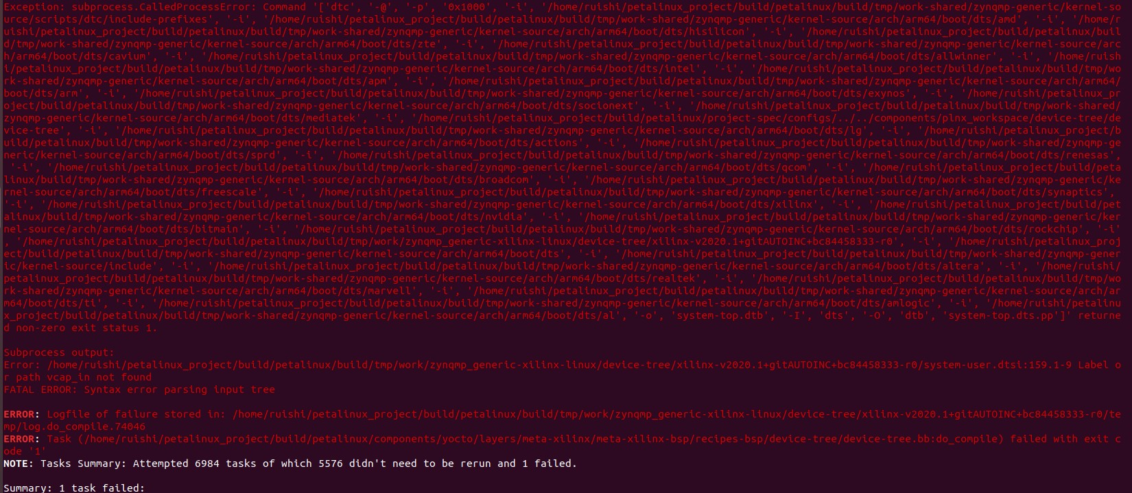
个人能力无法解决,未知原因,该是设备树配置问题,迫切欢迎有该方面调试经验者交流学习;