前言
由于最近开始找数字IC的工作,所以准备多练笔试题,下面贴上芯源笔试题,来源微信公众号<数字IC打工人>
参考资源:
1. mu_guang_
2. 李锐博恩
3. 长弓的坚持
4. https://yunyaniu.blog.csdn.net/
笔试题
1、Please code the divider by 3 with Verilog(50% duty cycle).用Verilog设计一个3分频器,要求50%占空比。

 1 module div_clk (
 2 input           wire          clk,
 3 input            wire          rst_n,
 4 output          wire          div_clk
 5
 6 );
 7
 8 parameter  DIV = 3;
 9
10 reg             [31:0]          pos_cnt;
11 wire             pos_clk;
12 reg             [31:0]           neg_cnt;
13 wire             neg_clk;
14
15 //上升沿分频
16 always@(posedge clk or negedge rst_n)begin
17 if(!rst_n)begin
18   pos_cnt <= 'd0;
19 end
20 else if(pos_cnt==DIV-1)begin
21  pos_cnt<= 'd0;
22 end
23 else begin
24 pos_cnt<= pos_cnt+1'd1;
25 end
26
27 end
28
29 assign pos_clk =(pos_cnt<DIV/2)? 0: 1;
30 //下降沿分频
31 always@(negedge clk or negedge rst_n)begin
32 if(!rst_n)begin
33   neg_cnt <= 'd0;
34 end
35 else if(neg_cnt==DIV-1)begin
36  neg_cnt<= 'd0;
37 end
38 else begin
39 neg_cnt<= neg_cnt+1'd1;
40 end
41
42 end
43
44 assign neg_clk =(neg_cnt<DIV/2)? 0: 1;
45
46 //奇偶判断后,输出分频时钟
47
48 assign div_clk = (DIV[0]==1)?(pos_clk&neg_clk) : pos_clk;
49
50 endmodule
2、Please describe the digital P&R flow.请简述数字后端P&R流程。
后端设计流程:
1、可测性设计——DFT
Design ForTest,可测性设计。芯片内部往往都自带测试电路,DFT的目的就是在设计的时候就考虑将来的测试。DFT的常见方法就是,在设计中插入扫描链,将非扫描单元(如寄存器)变为扫描单元。关于DFT,有些书上有详细介绍,对照图片就好理解一点。
DFT工具:Synopsys的DFT Compiler
2、布局规划(FloorPlan)
布局规划就是放置芯片的宏单元模块,在总体上确定各种功能电路的摆放位置,如IP模块,RAM,I/O引脚等等。布局规划能直接影响芯片最终的面积。
工具为Synopsys的Astro。
3、时钟树综合——CTS
Clock Tree Synthesis,时钟树综合,简单点说就是时钟的布线。
由于时钟信号在数字芯片的全局指挥作用,它的分布应该是对称式的连到各个寄存器单元,从而使时钟从同一个时钟源到达各个寄存器时,时钟延迟差异最小。这也是为什么时钟信号需要单独布线的原因。
CTS工具,Synopsys Physical Compiler。
4、布线(Place & Route)
这里的布线就是普通信号布线了,包括各种标准单元(基本逻辑门电路)之间的走线。比如我们平常听到的0.13um工艺,或者说90nm工艺,实际上就是这里金属布线可以达到的最小宽度,从微观上看就是MOS管的沟道长度。
工具Synopsys的Astro
5、寄生参数提取
由于导线本身存在的电阻,相邻导线之间的互感,耦合电容在芯片内部会产生信号噪声,串扰和反射。这些效应会产生信号完整性问题,导致信号电压波动和变化,如果严重就会导致信号失真错误。提取寄生参数进行再次的分析验证,分析信号完整性问题是非常重要的。
工具Synopsys的Star-RCXT
6、版图物理验证
对完成布线的物理版图进行功能和时序上的验证,验证项目很多,
如LVS(Layout Vs Schematic)验证,简单说,就是版图与逻辑综合后的门级电路图的对比验证;
DRC(Design Rule Checking):设计规则检查,检查连线间距,连线宽度等是否满足工艺要求;
ERC(Electrical Rule Checking):电气规则检查,检查短路和开路等电气规则违例;等等。
工具为Synopsys的Hercules
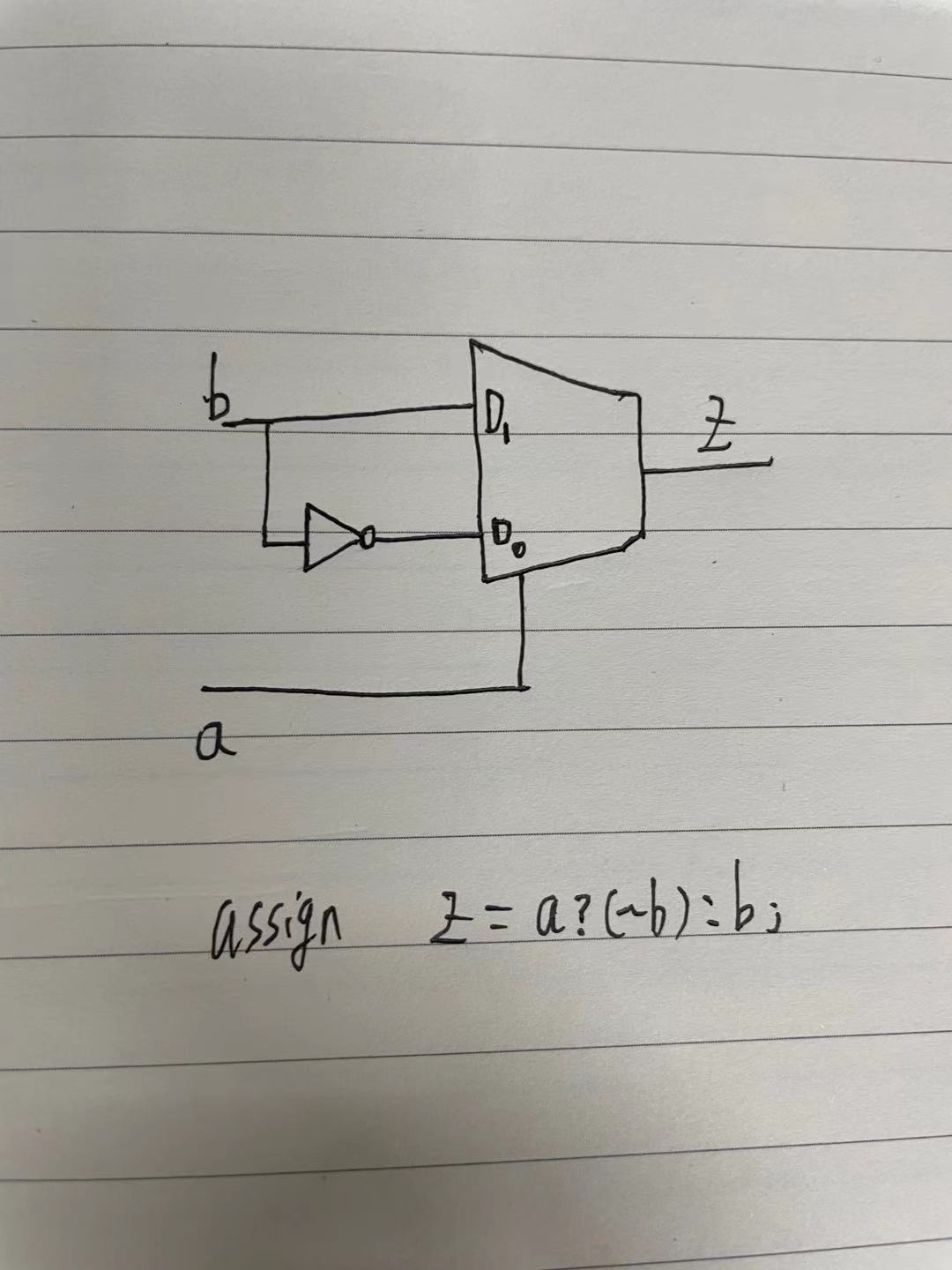
3、Please use a MUX and INV to implement aXOR.如何用一个2选一的MUX和一个INV实现异或。
verilog实现:
 1 module xor_rill
 2 (
 3 input a,
 4 input b,
 5
 6 output z
 7 );
 8
 9 assign z = a?(~b):b;
10
11 endmodule
电路结构图如下:

4、What are recovery and removal times?请描述recovery时间和removal时间的概念。
恢复时间:Recovery time
撤销复位时,恢复到非复位状态的电平必须在时钟有效沿来临之前的一段时间到来,才能保证有效的恢复到非复位状态,此段时间为Recovery time。类似于同步时钟的setup time

如图所示,rst_n为0表示复位,clk上升沿触发,rst_n从0到1上升沿与时钟上升沿之间的时间差必须不小于Recovery time才能保证寄存器恢复到正常状态。
我的理解,恢复时间为,撤销复位时,到下一个有效时钟上升沿的时间,如上图。
去除时间:Removal time
复位时,在时钟沿来临之后复位信号还需要保持的时间是去除时间,类似于同步时钟的 hold time。

如图所示,rst_n为0表示复位,clk上升沿触发,rst_n保持为0经过clk上升沿后仍需要保持一段时间,才能保证寄存器有效复位。
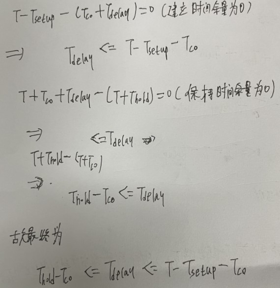
5、The clock cycle is T, the clock toregister output delay is Tco, setup and hold time of a register are Tsetup andThold, what's the Tdelay constrain?
时钟周期为T,时钟到寄存器输出延时Tco,寄存器建立时间Tsetup,寄存器保持时间Thold。请描述逻辑延时Tdelay的建立和保持时间要求(不考虑时钟延时)。

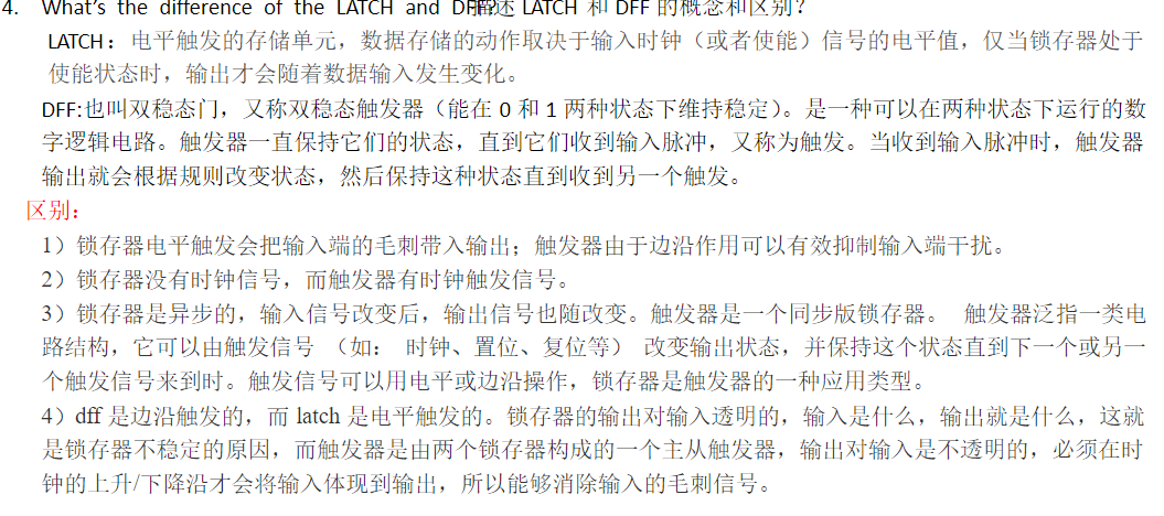
6、What's the difference between a LATCH anda DFF?请描述LATCH和DFF的概念和区别?

7、What's the difference between asynchronous and an asynchronous circuit?同步电路和异步电路的区别是什么?
同步电路:存储电路中所有触发器的时钟输入端都接同一个时钟脉冲源,因而所有触发器的状态的变化都与所加的时钟脉冲信号同步。
异步电路:电路中没有统一的时钟,有些触发器的时钟输入端与时钟脉冲源相连,只有这些触发器的状态与时钟同步,而其他的触发器状态变化不与时钟脉冲同步。
8、What is IR-drop, in which area will beeasy to have IR-drop problem ?什么是IR-drop,在那些地方容易出IR-drop问题?
IR压降是指出现在集成电路中电源和地网络上电压下降或升高的一种现象。
从电源布线的角度讲,那些远离电源端的地方,电源布线少的地方,容易出现ir-drop的问题。
从swtiching activity的角度讲,toggle rate高并且celldensiy高的地方IRdrop大,所以切记不要为了balance clock tree,把一堆clock buffer摆在一起。
9、How do you synchronize an asynchronousinput?异步信号如何进行同步?
方法:
1.采用两级触发器,减少可能出现的亚稳态影响;
2.异步FIFO和DPRAM;
3.握手协议,有效使能后,确认;
10、Please draw the state machine transmissiondiagram of the array detection 10010,code with Verilogand build the testbench and testcase to get 100% fsm coverage.画出可以检测10010序列的状态图,并用Verilog实现,搭建测试平台并写出可以达到100%状态机覆盖率的testcase。
状态图如下

序列检测,就是将一个指定序列从一个码流中识别出来,如10010从考虑码流为110010010000100101....,注意点,我的理解,即从IDEL状态开始未到最后一个状态,即未能连续检测到10010时,前面四个状态,都是直接顺序圈,看连续1个,2个,3个,4个能否出现我们预置的4个状态(S1,S2,S3,S4);在S5特别注意,此时再输入就为6个序列,输入X为1,类似地顺序全,连续1个,2个,3个,4个,5个,只能出现1,即状态S1,其他不符合,而输入0,则连续圈三个,出现100,符合状态S3。

  1 module SEQDET_FSM(
  2
  3     // INPUTS
  4
  5         Clk,        // posedge active
  6
  7         rst_n,      // negedge active
  8
  9         x,          // sequence input
 10
 11     // OUTPUTS
 12
 13         y           // detection "10010"
 14
 15     );
 16
 17
 18
 19     // Number of states = 6
 20
 21     parameter Idle    = 4'b0000;
 22
 23     parameter State_1 = 4'b0001; // 1
 24
 25     parameter State_2 = 4'b0010; // 10
 26
 27     parameter State_3 = 4'b0011; // 100
 28
 29     parameter State_4 = 4'b0100; // 1001
 30
 31     parameter State_5 = 4'b0101; // 10010
 32
 33
 34
 35     input              Clk;
 36
 37     input              rst_n;
 38
 39     input              x;
 40
 41
 42
 43     output             y;
 44
 45
 46
 47     reg                y;
 48
 49     reg     [3:0]      State_current;
 50
 51     reg     [3:0]      State_next;
 52
 53
 54
 55     // Synchronous timing always module, describing state transition
 56
 57     always@(posedge Clk or negedge rst_n)
 58
 59     begin
 60
 61         if(!rst_n)
 62
 63             State_current <= Idle;
 64
 65         else
 66
 67             State_current <= State_next;
 68
 69     end
 70
 71
 72
 73     // Combinational logic always module, judging state transition
 74
 75     always@(State_current or x)
 76
 77     begin
 78
 79         case(State_current)
 80
 81             Idle:
 82
 83             begin
 84
 85                 if(x)
 86
 87                     State_next = State_1;       // detect 1
 88
 89                 else
 90
 91                     State_next = State_current;
 92
 93             end
 94
 95             State_1:
 96
 97             begin
 98
 99                 if(!x)
100
101                     State_next = State_2;       // detect 10
102
103                 else
104
105                     State_next = State_1;       // detect 1
106
107             end
108
109             State_2:
110
111             begin
112
113                 if(!x)
114
115                     State_next = State_3;       // detect 100
116
117                 else
118
119                     State_next = State_1;       // detect 1
120
121             end
122
123             State_3:
124
125             begin
126
127                 if(x)
128
129                     State_next = State_4;       // detect 1001
130
131                 else
132
133                     State_next = Idle;          // detect 0
134
135             end
136
137             State_4:
138
139             begin
140
141                 if(!x)
142
143                     State_next = State_5;       // detect 10010
144
145                 else
146
147                     State_next = State_1;       // detect 1
148
149             end
150
151             State_5:
152
153             begin
154
155                 if(x)
156
157                     State_next = State_1;       // detect 1
158
159                 else
160
161                     State_next = State_3;       // detect 100
162
163             end
164
165             default:State_next = Idle;
166
167         endcase
168
169     end
170
171     // next_state output
172
173     always@(posedge Clk or negedge rst_n)
174
175     begin
176
177         if(!rst_n)
178
179             y <= 1'b0; // reset
180
181         else begin
182
183             case(State_next)
184
185                 Idle:
186
187                     y <= 1'b0;
188
189                 State_1:
190
191                     y <= 1'b0;
192
193                 State_2:
194
195                     y <= 1'b0;
196
197                 State_3:
198
199                     y <= 1'b0;
200
201                 State_4:
202
203                     y <= 1'b0;
204
205                 State_5:
206
207                     y <= 1'b1;              // detect 10010
208
209                 default:
210
211                     y <= 1'b0;
212
213             endcase
214
215         end
216
217     end
218
219 //https://www.bilibili.com/read/cv10936528 出处:bilibili
11、What are gate-level simulations? You havea device that can be programmed via an 12C interface. What type of tests do yourecommend to run for gate level only?什么是门级仿真(后仿)?如果你有一个设备通过12C接口配置,有哪些针对门级仿真的测试用例?
12、Please constrain the timing of clock andinput signal in the waveform, both are input pins for a chip. 请对下图中的输入时钟和输入数据进行时序约束。

13、There is an X present in my gate-levelsimulation due to a timing violation. How do you identify the source of it andthe type of violation? 如果在后仿中波形中出现了X,如何去定位,且可能是什么问题?
14、Please describe the ECO flow(includingpre-mask ECO and post-mask ECO).请描述ECO流程,包括pre-mask和post-mask ECO。
ECO有两种,pre-mask ECO和post-mask ECO,它的分界线就是base later tape out之前和之后。pre-mask ECO的流程是
1)后端写出网表,给前端
2)前端修改这个网表(一般不再做综合),可以使用任何标准单元(只要不是dont_use),交给后端
3)后端读入ECO网表,和ECO之前的place和route
4)ECO place&route,STA, DRC/LVS
post-mask ECO流程,假设你不想动base layer
1)后端写出网表,给前端
2)前端修改这个网表(一般不再做综合),只能使用spare cell或者像gate array一样的ECO cell
3)后端读入ECO网表,和ECO之前的place 和route
4)如果使用spare cell,不用ECO place;如果用ECO cell,要将ECO cell放在以前带gate array功能的fill cell的位置上,再按照指定的layer做ECO route。
15、What are various techniques to resolverouting congestion?如何解决routing congestion问题?
1. Change the power strap metal to a higher layer so that it does not impact cell placement.
2. Change the location of the power strap routes to avoid the congested area.
提示:
1) routing congestion发生在后端,前端一般不太考虑这个问题,需要后端自己去想办法解决,但是解决的办法不只在后端,也有一些方法需要前端的配合
2) 阻塞有多种情形,要分别讨论,没有一个统一的解决办法。
答案:
1)阻塞在RAM(macro)之间:可能RAM之间的距离没有计算正确,可以加大RAM之间的间距;扭转RAM的方向,使得RAM的IO pin朝向更容易走线的那边;如果是多个RAM共用地址或者数据线,尽量把RAM的地址数据pin对齐
2)阻塞出现在RAM和帮助单元交界的地方:在RAM周围加一条halo(keepout);把RAM放在四周,尽量把中间留下的空间变成方形;在有阻塞的地方加一些由小的placement blockage组成的矩阵
3)阻塞出现在标准单元的某一块:也可以加一些由小的placement blockage组成的矩阵;module/instance padding;利用placement guide减少那块地方的标准单元个数;scan chain reordering也会改善一些阻塞;定义density上限;使用congestion driven的placement,并且要求place之后做congestion优化;在综合是禁止使用那些pin太多太密集的标准单元(多半是那些复 杂的组合逻辑单元);请前端使用RAM代替触发器矩阵;请前端修改算法
4)应该尽量减少power route占有的资源,谨慎选择power mesh使用的金属层,VIA的大小等。在detail route完成之后,你如果已经试了各种解决signal congestion的方法,还有少量DRC无法解决时,可以考虑切掉部分power mesh
16、Please describe the rtl with INV, AND, OR andDFF. 请用与、或、非门和寄存器画出代码所描述的电路。
always@(posedgeclk or negedge rst_n)
begin
if(!rst_n)
begin
cnt<= 2'd0;
end
else if(cnt_en)
begin
if(ina)
cnt <= cnt+2'd1;
end
else
begin
cnt <=2'd0;
end
end
17、What are the different sources of powerconsumption? Please describe different techniques used to reduce powerconsumption.芯片的功耗分为哪种类型,请描述降低功耗的方式。
CMOS电路功耗主要由动态功耗和静态功耗组成,动态功耗又分为开关功耗、短路功耗两部分.
RTL级
1.并行结构:并行结构一定程度可以减低某一区域的频率,从而可能降低功耗。
2.流水结构:“路径长度缩短为原始路径长度的1 /M。这样,一个时钟周期内充/放电电容变为C/M。如果在加入流水线之后,时钟速度不变,则在一个周期内,只需要对C/M进行充/放电,而不是原来对C进行充/放电。因此,在相同的速度要求下,可以采用较低的电源电压来驱动系统。”
3.优化编码:通过数据编码来降低开关活动,例如用格雷码取代二进制。
4.操作数隔离:“操作数隔离的原理就是:如果在某一段时间内,数据通路的输出是无用的,则将它的输入置成个固定值,这样,数据通路部分没有翻转,功耗就会降低。”
4.2 门级电路
1.门控时钟技术: 芯片工作时,很大一部分功耗是由于时钟网络的翻转消耗的,控技术基本原理就是通过关闭芯片上暂时用不到的功能和它的时钟,从而实现节省电流消耗的目的,门控时钟对翻转功耗和内部功耗的抑制作用最强,是低功耗设计中的一种最有效的方法。
2.多电压供电
3.多阈值电压
根据多阈值电压单元的特点,为了满足时序的要求,关键路径中使用低阈值电压的单元(low Vt cells),以减少单元门的延迟,改善路径的时序。而为了减少静态功耗,在非关键路径中使用高阈值电压的单元(high Vt cells),以降低静态功耗。因此,使用多阈值电压的工艺库,我们可以设计出低静态功耗和高性能的设计。
4.动态电压调节
5.动态频率调节
————————————————
原文链接:https://blog.csdn.net/mu_guang_/article/details/115719673
