linux内核SPI总线驱动分析(一)(转)
下面有两个大的模块:
一个是SPI总线驱动的分析 (研究了具体实现的过程)
另一个是SPI总线驱动的编写(不用研究具体的实现过程)
SPI总线驱动分析
1 SPI概述
SPI是英语Serial Peripheral interface的缩写,顾名思义就是串行外围设备接口,是Motorola首先在其MC68HCXX系列处理器上定义的。SPI接口主要应用在 EEPROM,FLASH,实时时钟,AD转换器,还有数字信号处理器和数字信号解码器之间。SPI是一种高速的,全双工,同步的通信总线,并且在芯片的管脚上只占用四根线,节约了芯片的管脚,同时为PCB的布局上节省空间,提供方便。
SPI的通信原理很简单,它以主从方式工作,这种模式通常有一个主设备和一个或多个从设备,需要4根线,事实上3根也可以。也是所有基于SPI的设备共有的,它们是SDI(数据输入),SDO(数据输出),SCLK(时钟),CS(片选)。
MOSI(SDO):主器件数据输出,从器件数据输入。
MISO(SDI):主器件数据输入,从器件数据输出。
SCLK :时钟信号,由主器件产生。
CS:从器件使能信号,由主器件控制。
其中CS是控制芯片是否被选中的,也就是说只有片选信号为预先规定的使能信号时(高电位或低电位),对此芯片的操作才有效,这就允许在同一总线上连接多个SPI设备成为可能。需要注意的是,在具体的应用中,当一条SPI总线上连接有多个设备时,SPI本身的CS有可能被其他的GPIO脚代替,即每个设备的CS脚被连接到处理器端不同的GPIO,通过操作不同的GPIO口来控制具体的需要操作的SPI设备,减少各个SPI设备间的干扰。
SPI是串行通讯协议,也就是说数据是一位一位从MSB或者LSB开始传输的,这就是SCK时钟线存在的原因,由SCK提供时钟脉冲,MISO、MOSI则基于此脉冲完成数据传输。 SPI支持4-32bits的串行数据传输,支持MSB和LSB,每次数据传输时当从设备的大小端发生变化时需要重新设置SPI Master的大小端。
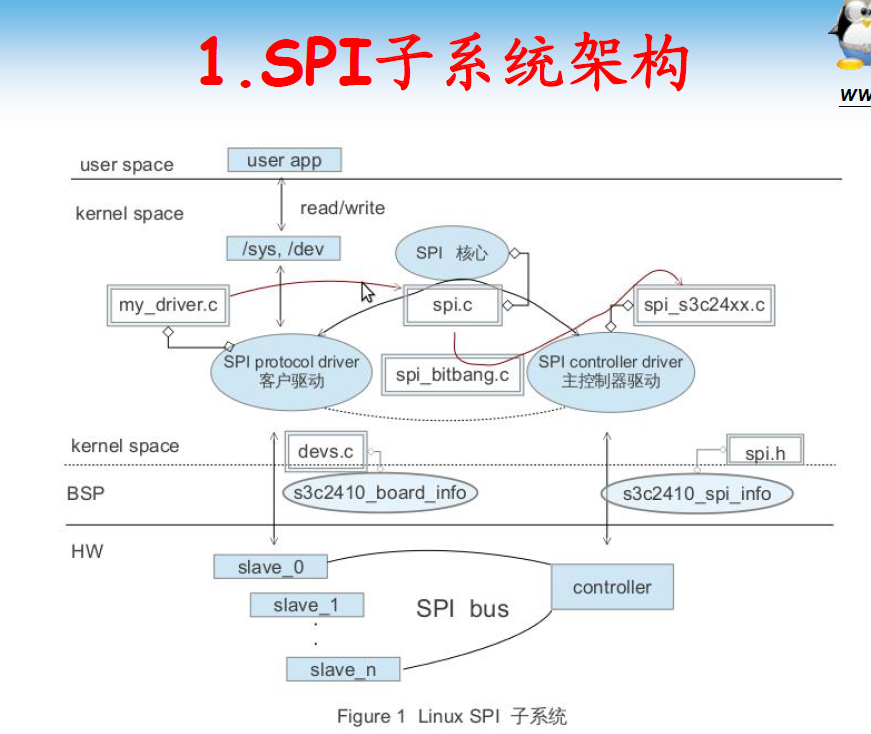
2 Linux SPI驱动总体架构
在2.6的linux内核中,SPI的驱动架构可以分为如下三个层次:SPI 核心层、SPI控制器驱动层和SPI设备驱动层。
Linux 中SPI驱动代码位于drivers/spi目录。
2.1 SPI核心层
SPI核心层是Linux的SPI核心部分,提供了核心数据结构的定义、SPI控制器驱动和设备驱动的注册、注销管理等API。其为硬件平台无关层,向下屏蔽了物理总线控制器的差异,定义了统一的访问策略和接口;其向上提供了统一的接口,以便SPI设备驱动通过总线控制器进行数据收发。
Linux中,SPI核心层的代码位于driver/spi/ spi.c。由于该层是平台无关层,本文将不再叙述,有兴趣可以查阅相关资料。
2.2 SPI控制器驱动层
SPI控制器驱动层,每种处理器平台都有自己的控制器驱动,属于平台移植相关层。它的职责是为系统中每条SPI总线实现相应的读写方法。在物理上,每个SPI控制器可以连接若干个SPI从设备。
在系统开机时,SPI控制器驱动被首先装载。一个控制器驱动用于支持一条特定的SPI总线的读写。一个控制器驱动可以用数据结构struct spi_master来描述。
在include/liunx/spi/spi.h文件中,在数据结构struct spi_master定义如下:
struct spi_master {
    struct device   dev;
    s16         bus_num;
    u16         num_chipselect;
    int         (*setup)(struct spi_device *spi);
    int         (*transfer)(struct spi_device *spi, struct spi_message *mesg);
    void        (*cleanup)(struct spi_device *spi);
};
bus_num为该控制器对应的SPI总线号。
num_chipselect 控制器支持的片选数量,即能支持多少个spi设备
setup函数是设置SPI总线的模式,时钟等的初始化函数, 针对设备设置SPI的工作时钟及数据传输模式等。在spi_add_device函数中调用。
transfer函数是实现SPI总线读写方法的函数。实现数据的双向传输,可能会睡眠
cleanup注销时候调用
2.3 SPI设备驱动层
SPI设备驱动层为用户接口层,其为用户提供了通过SPI总线访问具体设备的接口。
SPI设备驱动层可以用两个模块来描述,struct spi_driver和struct spi_device。
相关的数据结构如下:
struct spi_driver {
    int         (*probe)(struct spi_device *spi);
    int         (*remove)(struct spi_device *spi);
    void            (*shutdown)(struct spi_device *spi);
    int         (*suspend)(struct spi_device *spi, pm_message_t mesg);
    int         (*resume)(struct spi_device *spi);
    struct device_driver    driver;
};
Driver是为device服务的,spi_driver注册时会扫描SPI bus上的设备,进行驱动和设备的绑定,probe函数用于驱动和设备匹配时被调用。从上面的结构体注释中我们可以知道,SPI的通信是通过消息队列机制,而不是像I2C那样通过与从设备进行对话的方式。
struct spi_device {
    struct device       dev;
    struct spi_master   *master;
    u32         max_speed_hz;
    u8          chip_select;
    u8          mode;
    u8          bits_per_word;
    int         irq;
    void            *controller_state;
    void            *controller_data;
    char            modalias[32];
};
.modalias = "m25p10",
.mode =SPI_MODE_0, //CPOL=0, CPHA=0 此处选择具体数据传输模式
.max_speed_hz = 10000000, //最大的spi时钟频率
/* Connected to SPI-0 as 1st Slave */
.bus_num = 0, //设备连接在spi控制器0上
.chip_select = 0, //片选线号,在S5PC100的控制器驱动中没有使用它作为片选的依据,而是选择了下文controller_data里的方法。
.controller_data = &smdk_spi0_csi[0],
通常来说spi_device对应着SPI总线上某个特定的slave。并且spi_device封装了一个spi_master结构体。spi_device结构体包含了私有的特定的slave设备特性,包括它最大的频率,片选那个,输入输出模式等等
4 spi_device以下一系列的操作是在platform板文件中完成!
struct spi_board_info {
charmodalias[SPI_NAME_SIZE];
const void*platform_data;
void*controller_data;
intirq;
u32max_speed_hz;
u16bus_num;
u16chip_select;
u8mode;
};
这个结构体记录了SPI外设使用的主机控制器序号、片选信号、数据比特率、SPI传输方式等
构建的操作是以下的两个步骤:
1.
static struct spi_board_info s3c_spi_devs[] __initdata = {

{

.modalias = "m25p10a",

.mode = SPI_MODE_0,

.max_speed_hz = 1000000,

.bus_num = 0,

.chip_select = 0,

.controller_data = &smdk_spi0_csi[SMDK_MMCSPI_CS],

},

};
2.
而这个info在init函数调用的时候会初始化:
spi_register_board_info(s3c_spi_devs,ARRAY_SIZE(s3c_spi_devs));
spi_register_board_info(s3c_spi_devs,ARRAY_SIZE(s3c_spi_devs));//注册spi_board_info。这个代码会把spi_board_info注册到链表board_list上。spi_device封装了一个spi_master结构体,事实上spi_master的注册会在spi_register_board_info之后,spi_master注册的过程中会调用scan_boardinfo扫描board_list,找到挂接在它上面的spi设备,然后创建并注册spi_device。
至此spi_device就构建并注册完成了!!!!!!!!!!!!!
5 spi_driver的构建与注册
driver有几个重要的结构体:spi_driver、spi_transfer、spi_message
driver有几个重要的函数 :spi_message_init、spi_message_add_tail、spi_sync
//spi_driver的构建
static struct spi_driver   m25p80_driver = {

.driver = {

        .name   ="m25p80",

        .bus    =&spi_bus_type,

        .owner  = THIS_MODULE,

    },

    .probe  = m25p_probe,

    .remove =__devexit_p(m25p_remove),

};
//spidriver的注册
spi_register_driver(&m25p80_driver);
在有匹配的spi_device时,会调用m25p_probe
probe里完成了spi_transfer、spi_message的构建;
spi_message_init、spi_message_add_tail、spi_sync、spi_write_then_read函数的调用
例如:
 */
static int m25p10a_read( struct m25p10a *flash, loff_t from,
        size_t len, char *buf )
{
    int r_count = 0, i;
    struct spi_transfer st[2];
    struct spi_message  msg;

    spi_message_init( &msg );
    memset( st, 0, sizeof(st) );

    flash->cmd[0] = CMD_READ_BYTES;
    flash->cmd[1] = from >> 16;
    flash->cmd[2] = from >> 8;
    flash->cmd[3] = from;

    st[ 0 ].tx_buf = flash->cmd;
    st[ 0 ].len = CMD_SZ;
    spi_message_add_tail( &st[0], &msg );

    st[ 1 ].rx_buf = buf;
    st[ 1 ].len = len;
    spi_message_add_tail( &st[1], &msg );

    mutex_lock( &flash->lock );

    /* Wait until finished previous write command. */
    if (wait_till_ready(flash)) {
        mutex_unlock( &flash->lock );
        return -1;
    }

    spi_sync( flash->spi, &msg );
    r_count = msg.actual_length - CMD_SZ;
    printk( "in (%s): read %d bytes
", __func__, r_count );
    for( i = 0; i < r_count; i++ ) {
        printk( "0x%02x
", buf[ i ] );
    }

    mutex_unlock( &flash->lock );
    return 0;
}
static int m25p10a_write( struct m25p10a *flash, loff_t to,
        size_t len, const char *buf )
{
    int w_count = 0, i, page_offset;

    struct spi_transfer st[2];

    struct spi_message  msg;
    write_enable( flash );  //写使能

        spi_message_init( &msg );

    memset( st, 0, sizeof(st) );

    flash->cmd[0] = CMD_PAGE_PROGRAM;
    flash->cmd[1] = to >> 16;
    flash->cmd[2] = to >> 8;
    flash->cmd[3] = to;

    st[ 0 ].tx_buf = flash->cmd;
    st[ 0 ].len = CMD_SZ;
  //填充spi_transfer,将transfer放在队列后面
    spi_message_add_tail( &st[0], &msg );

    st[ 1 ].tx_buf = buf;
    st[ 1 ].len = len;
    spi_message_add_tail( &st[1], &msg );


        spi_sync( flash->spi, &msg );   调用spi_master发送spi_message

    return 0;
}
static int m25p10a_probe(struct spi_device *spi)
{
    int ret = 0;
    struct m25p10a  *flash;
    char buf[ 256 ];
    flash = kzalloc( sizeof(struct m25p10a), GFP_KERNEL );
    flash->spi = spi;
    /* save flash as driver's private data */
    spi_set_drvdata( spi, flash );
    memset( buf, 0x7, 256 );
    m25p10a_write( flash, 0, 20, buf); //0地址写入20个7
    memset( buf, 0, 256 );
    m25p10a_read( flash, 0, 25, buf ); //0地址读出25个数

    return 0;
}
到目前为止,完成了SPI的驱动和应用