Calculating Stereo PairsWritten by Paul BourkeJuly 1999 IntroductionThe following discusses computer based generation of stereo pairs as used to create a perception of depth. Such depth perception can be useful in many fields, for example, scientific visualisation, entertainment, games, appreciation of architectural spaces, etc. Depth cuesThere are a number of cues that the human visual system uses that result in a perception of depth. Some of these are present even in two dimensional images, for example:
There are other cues that are not present in 2D images, they are:
While binocular disparity is considered the dominant depth cue in most people, if the other cues are presented incorrectly they can have a strong detrimental effect. In order to render a stereo pair one needs to create two images, one for each eye in such a way that when independently viewed they will present an acceptable image to the visual cortex and it will fuse the images and extract the depth information as it does in normal viewing. If stereo pairs are created with a conflict of depth cues then one of a number of things may occur: one cue may become dominant and it may not be the correct/intended one, the depth perception will be exaggerated or reduced, the image will be uncomfortable to watch, the stereo pairs may not fuse at all and the viewer will see two separate images. Stereographics using stereo pairs is only one of the major stereo3D dimensional display technologies, others include holographic and lenticular (barrier strip) systems both of which are autostereoscopic. Stereo pairs create a "virtual" three dimensional image, binocular disparity and convergence cues are correct but accommodation cues are inconsistent because each eye is looking at a flat image. The visual system will tolerate this conflicting accommodation to a certain extent, the classical measure is normally quoted as a maximum separation on the display of 1/30 of the distance of the viewer to the display. The case where the object is behind the projection plane is illustrated below. The projection for the left eye is on the left and the projection for the right eye is on the right, the distance between the left and right eye projections is called the horizontal parallax. Since the projections are on the same side as the respective eyes, it is called a positive parallax. Note that the maximum positive parallax occurs when the object is at infinity, at this point the horizontal parallax is equal to the interocular distance. 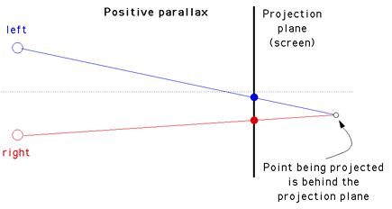 If an object is located in front of the projection plane then the projection for the left eye is on the right and the projection for the right eye is on the left. This is known as negative horizontal parallax. Note that a negative horizontal parallax equal to the interocular distance occurs when the object is half way between the projection plane and the center of the eyes. As the object moves closer to the viewer the negative horizontal parallax increases to infinity. 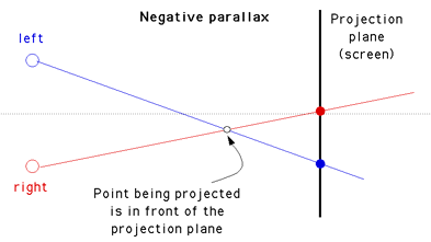 If an object lies at the projection plane then its projection onto the focal plane is coincident for both the left and right eye, hence zero parallax. 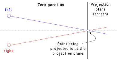 RenderingThere are a couple of methods of setting up a virtual camera and rendering two stereo pairs, many methods are strictly incorrect since they introduce vertical parallax. An example of this is called the "Toe-in" method, while incorrect it is still often used because the correct "off axis" method requires features not always supported by rendering packages. Toe-in is usually identical to methods that involve a rotation of the scene. The toe-in method is still popular for the lower cost filming because offset cameras are uncommon and it is easier than using parallel cameras which requires a subsequent trimming of the stereo pairs. Toe-in (Incorrect)In this projection the camera has a fixed and symmetric aperture, each camera is pointed at a single focal point. Images created using the "toe-in" method will still appear stereoscopic but the vertical parallax it introduces will cause increased discomfort levels. The introduced vertical parallax increases out from the center of the projection plane and is more important as the camera aperture increases.  Off-axis (Correct) This is the correct way to create stereo pairs. It introduces no vertical parallax and is therefore creates the less stressful stereo pairs. Note that it requires a non symmetric camera frustum, this is supported by some rendering packages, in particular, OpenGL. 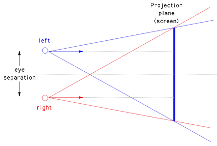 Objects that lie in front of the projection plane will appear to be in front of the computer screen, objects that are behind the projection plane will appear to be "into" the screen. It is generally easier to view stereo pairs of objects that recede into the screen, to achieve this one would place the focal point closer to the camera than the objects of interest. Note, this doesn't lead to as dramatic an effect as objects that pop out of the screen. The degree of the stereo effect depends on both the distance of the camera to the projection plane and the separation of the left and right camera. Too large a separation can be hard to resolve and is known as hyperstereo. A good ballpark separation of the cameras is 1/20 of the distance to the projection plane, this is generally the maximum separation for comfortable viewing. Another constraint in general practice is to ensure the negative parallax (projection plane behind the object) does not exceed the eye separation. A common measure is the parallax angle defined as thea = 2 atan(DX / 2d) where DX is the horizontal separation of a projected point between the two eyes and d is the distance of the eye from the projection plane. For easy fusing by the majority of people, the absolute value of theta should not exceed 1.5 degrees for all points in the scene. Note theta is positive for points behind the scene and negative for points in front of the screen. It is not uncommon to restrict the negative value of theta to some value closer to zero since negative parallax is more difficult to fuse especially when objects cut the boundary of the projection plane. 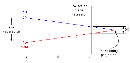
Getting started with ones first stereo rendering can be a hit and miss affair, the following approach should ensure success. First choose the camera aperture, this should match the "sweet spot" for your viewing setup, typically between 45 and 60 degrees). Next choose a focal length, the distance at which objects in the scene will appear to be at zero parallax. Objects closer than this will appear in front of the screen, objects further than the focal length will appear behind the screen. How close objects can come to the camera depends somewhat on how good the projection system is but closer than half the focal length should be avoided. Finally, choose the eye separation to be 1/30 of the focal length. ReferencesBailey, M, Clark DUsing ChromaDepth to Obtain Inexpensive Single-image Stereovision for Scientific Visualisation Journal of Graphics Tools, ACM, Vol 3 No 3 pp1-9 Baker, J. Bos, P. et al Bos, P. et al Grotch, S.L. Hodges, L.F. and McAllister, D.F. Lipton, L, Meyer, L Lipton, L., Ackerman.,M Nakagawa, K., Tsubota, K., Yamamoto, K Roese, J.A. and McCleary, L.E. Southard, D.A Course notes, #24 Weissman, M. 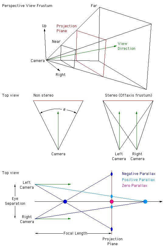 Creating correct stereo pairs from any raytracerWritten by Paul BourkeFebruary 2001 Contribution by Chris Gray: AutoXidMary.mcr, a camera configuration for 3DStudioMax that uses the XidMary Camera. Introduction Many rendering packages provide the necessary tools to create correct stereo pairs (eg: OpenGL), other packages can transform their geometry appropriately (translations and shears) so that stereo pairs can be directly created, many rendering packages only provide straightforward perspective projections. The following describes a method of creating stereo pairs using such packages. While it is possible to create stereo pairs using PovRay with shear transformations, PovRay will be used to illustrate this technique which can be applied to any rendering software that supports only perspective projections (this method is often easier than the translate/shear matrix method). Basic ideaCreating stereo pairs involves rendering the left and right eye views from two positions separated by a chosen eye spacing. The eye (camera) looks along parallel vectors. The frustum from each eye to each corner of the projection plane is asymmetric. The solution to creating correct stereo pairs using only symmetric fristums is to extend the frustum (horizontally) for each eye (camera) making it symmetric. After rendering, those parts of the image resulting from the extended fustrum are timmed off. The camera geometry is illustrated below, the relevant details can be translated into the camera specification for your favourite rendering package. 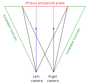 All that remains is to calculate the amount of trimming required for a given focal length and eye separation. Since one normally has a target image width it is usual to render the image larger so that after the trim the image is the desired size. The amount of offset depends on the desired focal length, that is, the distance at which there is no vertical parallax. The amount by which the images are extended and then trimmed (working not given) is given by the following:
Where "w" is the image width, "fo" the focal length (zero parallax), "e" the eye separation, and "a" the intended horizontal aperture. In order to get the final aperture "a" after the image is trimmed, the actual aperture "a'" needs to be modified as follows.
Note that not all rendering packages use the horizontal aperture but rather a vertical aperture eg: OpenGL. As expected as the focal length tends to infinity the amount by which the images are trimmed tends to 0, similarly as the eye separation tends to 0. To combine the images, delta is trimmed off the left of the left image and delta pixels are trimmed off the right of the right image. Example 1Consider a PovRay model scene file for stereo pair rendering where the eye separation is 0.2, the focal length (zero parallax) is 3, the aperture 60 degrees, and the final image size is supposed to be 800 by 600....delta comes to 46. Example PovRay model files are given for each camera. Note that one could ask PovRay to render just the intended regions of each image by setting a start and end column.
Example 2 
Creating stereoscopic images that are easy on the eyesWritten by Paul BourkeFebruary 2003 There are some unique considerations when creating effective stereoscopic images whether as still images, interactive environments, or animations/movies. In the discussion of these given below it will be assumed that the correct stereopairs have been created, that is, perspective projection with parallel cameras resulting is the so called offaxis projection. It should be noted that not all of these are hard and fast rules and they may be inherent in the type of image content being created.
3D Stereo Rendering
Source code for the incorrect (but close) "Toe-in" stereo, |
| Toe-in Method
A common approach is the so called "toe-in" method where the camera for the left and right eye is pointed towards a single focal point and gluPerspective() is used. |
 |
glMatrixMode(GL_PROJECTION);
glLoadIdentity();
gluPerspective(camera.aperture,screenwidth/(double)screenheight,0.1,10000.0);
if (stereo) {
CROSSPROD(camera.vd,camera.vu,right);
Normalise(&right);
right.x *= camera.eyesep / 2.0;
right.y *= camera.eyesep / 2.0;
right.z *= camera.eyesep / 2.0;
glMatrixMode(GL_MODELVIEW);
glDrawBuffer(GL_BACK_RIGHT);
glClear(GL_COLOR_BUFFER_BIT | GL_DEPTH_BUFFER_BIT);
glLoadIdentity();
gluLookAt(camera.vp.x + right.x,
camera.vp.y + right.y,
camera.vp.z + right.z,
focus.x,focus.y,focus.z,
camera.vu.x,camera.vu.y,camera.vu.z);
MakeLighting();
MakeGeometry();
glMatrixMode(GL_MODELVIEW);
glDrawBuffer(GL_BACK_LEFT);
glClear(GL_COLOR_BUFFER_BIT | GL_DEPTH_BUFFER_BIT);
glLoadIdentity();
gluLookAt(camera.vp.x - right.x,
camera.vp.y - right.y,
camera.vp.z - right.z,
focus.x,focus.y,focus.z,
camera.vu.x,camera.vu.y,camera.vu.z);
MakeLighting();
MakeGeometry();
} else {
glMatrixMode(GL_MODELVIEW);
   glDrawBuffer(GL_BACK);
   glClear(GL_COLOR_BUFFER_BIT | GL_DEPTH_BUFFER_BIT);
glLoadIdentity();
gluLookAt(camera.vp.x,
camera.vp.y,
camera.vp.z,
focus.x,focus.y,focus.z,
camera.vu.x,camera.vu.y,camera.vu.z);
MakeLighting();
MakeGeometry();
}
/* glFlush(); This isn't necessary for double buffers */
glutSwapBuffers();
| Correct method
The Toe-in method while giving workable stereo pairs is not correct, it also introduces vertical parallax which is most noticeable for objects in the outer field of view. The correct method is to use what is sometimes known as the "parallel axis asymmetric frustum perspective projection". In this case the view vectors for each camera remain parallel and a glFrustum() is used to describe the perspective projection. |
 |
   /* Misc stuff */
   ratio  = camera.screenwidth / (double)camera.screenheight;
   radians = DTOR * camera.aperture / 2;
   wd2     = near * tan(radians);
   ndfl    = near / camera.focallength;

   if (stereo) {

      /* Derive the two eye positions */
      CROSSPROD(camera.vd,camera.vu,r);
      Normalise(&r);
      r.x *= camera.eyesep / 2.0;
      r.y *= camera.eyesep / 2.0;
      r.z *= camera.eyesep / 2.0;

      glMatrixMode(GL_PROJECTION);
      glLoadIdentity();
      left  = - ratio * wd2 - 0.5 * camera.eyesep * ndfl;
      right =   ratio * wd2 - 0.5 * camera.eyesep * ndfl;
      top    =   wd2;
      bottom = - wd2;
      glFrustum(left,right,bottom,top,near,far);

      glMatrixMode(GL_MODELVIEW);
      glDrawBuffer(GL_BACK_RIGHT);
      glClear(GL_COLOR_BUFFER_BIT | GL_DEPTH_BUFFER_BIT);
      glLoadIdentity();
      gluLookAt(camera.vp.x + r.x,camera.vp.y + r.y,camera.vp.z + r.z,
                camera.vp.x + r.x + camera.vd.x,
                camera.vp.y + r.y + camera.vd.y,
                camera.vp.z + r.z + camera.vd.z,
                camera.vu.x,camera.vu.y,camera.vu.z);
      MakeLighting();
      MakeGeometry();

      glMatrixMode(GL_PROJECTION);
      glLoadIdentity();
      left  = - ratio * wd2 + 0.5 * camera.eyesep * ndfl;
      right =   ratio * wd2 + 0.5 * camera.eyesep * ndfl;
      top    =   wd2;
      bottom = - wd2;
      glFrustum(left,right,bottom,top,near,far);

      glMatrixMode(GL_MODELVIEW);
      glDrawBuffer(GL_BACK_LEFT);
      glClear(GL_COLOR_BUFFER_BIT | GL_DEPTH_BUFFER_BIT);
      glLoadIdentity();
      gluLookAt(camera.vp.x - r.x,camera.vp.y - r.y,camera.vp.z - r.z,
                camera.vp.x - r.x + camera.vd.x,
                camera.vp.y - r.y + camera.vd.y,
                camera.vp.z - r.z + camera.vd.z,
                camera.vu.x,camera.vu.y,camera.vu.z);
      MakeLighting();
      MakeGeometry();

   } else {

      glMatrixMode(GL_PROJECTION);
      glLoadIdentity();
      left  = - ratio * wd2;
      right =   ratio * wd2;
      top    =   wd2;
      bottom = - wd2;
      glFrustum(left,right,bottom,top,near,far);

      glMatrixMode(GL_MODELVIEW);
      glDrawBuffer(GL_BACK);
      glClear(GL_COLOR_BUFFER_BIT | GL_DEPTH_BUFFER_BIT);
      glLoadIdentity();
      gluLookAt(camera.vp.x,camera.vp.y,camera.vp.z,
                camera.vp.x + camera.vd.x,
                camera.vp.y + camera.vd.y,
                camera.vp.z + camera.vd.z,
                camera.vu.x,camera.vu.y,camera.vu.z);
      MakeLighting();
      MakeGeometry();
   }

   /* glFlush(); This isn't necessary for double buffers */
   glutSwapBuffers();
Note that sometimes it is appropriate to use the left eye position when not in stereo mode in which case the above code can be simplified. It seems more elegant and consistent when moving between mono and stereo if the point between the eyes is used when in mono.
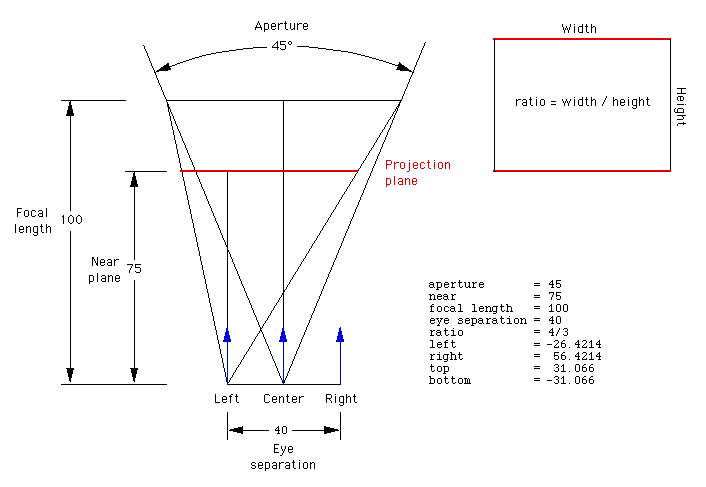
On the off chance that you want to write the code differently and would like to test the correctness of the glFrustum() parameters, here's an explicit example.
Passive stereo
Updated in May 2002: sample code to deal with passive stereo, that is, drawing the left eye to the left half of a dual display OpenGL card and the right eye to the right half. pulsar2.c and pulsar2.h
Macintosh OS-X exampleSource code and Makefile illustrating stereo under Mac OS-X using "blue line" syncing, contributed by Jamie Cate.
Demonstration stereo application for Mac OS-X from the Apple development site based upon the method and code described above: GLUTStereo. (Also uses blue line syncing)
Python Example contributed by Peter Roeschpython.zip
Cross-eye stereo modification contributed by Todd Marshall
pulsar_cross.c
Offaxis frustums - OpenGL
Written by Paul BourkeJuly 2007
The following describes one (there are are a number of alternatives) system for create perspective offset frustums for stereoscopic projection using OpenGL. This is convenient for non observer tracked viewing on a single stereoscopic panel in these cases there is no clear relationship between the model dimensions and the screen. Note that for multiwall immersive displays the following is not the best approach, the appropriate method requires a knowledge of the screen geometry and the observer position and generally the model is scaled into real world coordinates.
Camera is defined by its position, view direction, up vector, eye separation, distance to zero parallax (see fo below) and the near and far cutting planes. Position, eye separation, zero parallax distance, and cutting planes are most conveniently specified in model coordinates, direction and up vector are orthonormal vectors. With regard to parameters for adjusting stereoscopic viewing I would argue that the distance to zero parallax is the most natural, not only does it relate directly to the scale of the model and the relative position of the camera, it also has a direct bearing on the stereoscopic result ... namely that objects at that distance will appear to be at the depth of the screen. In order not to burden the operators with multiple stereo controls one can usually just internally set the eye separation to 1/30 of the zero parallax distance (camera.eyesep = camera.fo / 30), this will give acceptable stereoscopic viewing in almost all situations and is independent of model scale.
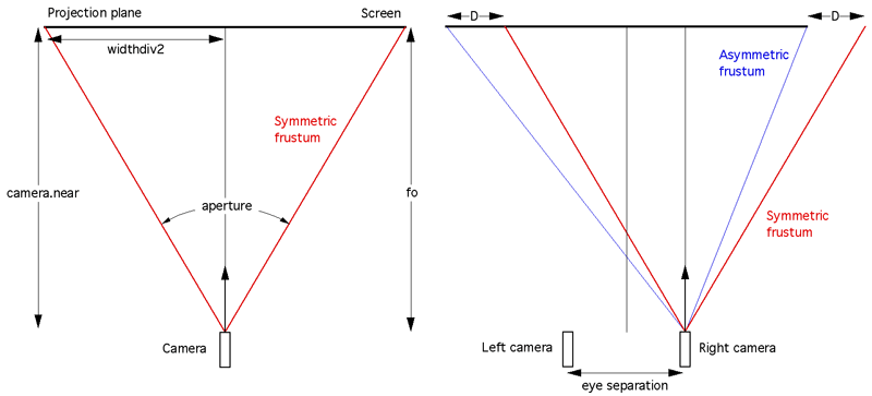
The above diagram (view from above the two cameras) is intended to illustrate how the amount by which to offset the frustums is calculated. Note there is only horizontal parallax. This is intended to be a guide for OpenGL programmers, as such there are some assumptions that relate to OpenGL that may not be appropriate to other APIs. The eye separation is exaggerated in order to make the diagram clearer.
The half width on the projection plane is given by
This is related to world coordinates by similar triangles, the amount D by which to offset the view frustum horizontally is given by
aspectratio = windowwidth / (double)windowheight;         // Divide by 2 for side-by-side stereo
widthdiv2   = camera.near * tan(camera.aperture / 2); // aperture in radians
cameraright = crossproduct(camera.dir,camera.up);         // Each unit vectors
right.x *= camera.eyesep / 2.0;
right.y *= camera.eyesep / 2.0;
right.z *= camera.eyesep / 2.0;
Symmetric - non stereo camera
   glMatrixMode(GL_PROJECTION);
   glLoadIdentity();
   glViewport(0,0,windowwidth,windowheight);
   top    =   widthdiv2;
   bottom = - widthdiv2;
   left   = - aspectratio * widthdiv2;
   right  =   aspectratio * widthdiv2;
   glFrustum(left,right,bottom,top,camera.near,camera.far);
   glMatrixMode(GL_MODELVIEW);
   glLoadIdentity();
   gluLookAt(camera.pos.x,camera.pos.y,camera.pos.z,
             camera.pos.x + camera.dir.x,
             camera.pos.y + camera.dir.y,
             camera.pos.z + camera.dir.z,
             camera.up.x,camera.up.y,camera.up.z);
   // Create geometry here in convenient model coordinates
Asymmetric frustum - stereoscopic
   // Right eye
   glMatrixMode(GL_PROJECTION);
   glLoadIdentity();
   // For frame sequential, earlier use glDrawBuffer(GL_BACK_RIGHT);
   glViewport(0,0,windowwidth,windowheight);
   // For side by side stereo
   //glViewport(windowwidth/2,0,windowwidth/2,windowheight);
   top    =   widthdiv2;
   bottom = - widthdiv2;
   left   = - aspectratio * widthdiv2 - 0.5 * camera.eyesep * camera.near / camera.fo;
   right  =   aspectratio * widthdiv2 - 0.5 * camera.eyesep * camera.near / camera.fo;
   glFrustum(left,right,bottom,top,camera.near,camera.far);
   glMatrixMode(GL_MODELVIEW);
   glLoadIdentity();
   gluLookAt(camera.pos.x + right.x,camera.pos.y + right.y,camera.pos.z + right.z,
             camera.pos.x + right.x + camera.dir.x,
             camera.pos.y + right.y + camera.dir.y,
             camera.pos.z + right.z + camera.dir.z,
             camera.up.x,camera.up.y,camera.up.z);
   // Create geometry here in convenient model coordinates

   // Left eye
   glMatrixMode(GL_PROJECTION);
   glLoadIdentity();
   // For frame sequential, earlier use glDrawBuffer(GL_BACK_LEFT);
   glViewport(0,0,windowwidth,windowheight);
   // For side by side stereo
   //glViewport(0,0,windowidth/2,windowheight);
   top    =   widthdiv2;
   bottom = - widthdiv2;
   left   = - aspectratio * widthdiv2 + 0.5 * camera.eyesep * camera.near / camera.fo;
   right  =   aspectratio * widthdiv2 + 0.5 * camera.eyesep * camera.near / camera.fo;
   glFrustum(left,right,bottom,top,camera.near,camera.far);
   glMatrixMode(GL_MODELVIEW);
   glLoadIdentity();
   gluLookAt(camera.pos.x - right.x,camera.pos.y - right.y,camera.pos.z - right.z,
             camera.pos.x - right.x + camera.dir.x,
             camera.pos.y - right.y + camera.dir.y,
             camera.pos.z - right.z + camera.dir.z,
             camera.up.x,camera.up.y,camera.up.z);
   // Create geometry here in convenient model coordinates
Notes
-
Due to the possibility of extreme negative parallax separation as objects come closer to the camera than the zero parallax distance, it is common practice to link the near cutting plane to the zero parallax distance. The exact relationship depends on the degree of ghosting of the projection system but camera.near = camera.fo / 5 is usually appropriate.
-
When the camera is adjusted, for example during a flight path, it is important to ensure the direction and up vectors remain orthonormal. This follows naturally when using quaternions and there are ways of ensuring this when using other systems for camera navigation.
-
Developers are encouraged to support both side-by-side stereo as well as frame sequential (also called quad buffer stereo). The only difference is the viewport parameters, setting the drawing buffer to either the back buffer or the left/right back buffers, and when to clear the back buffer(s).
-
The camera aperture above is the horizontal field of view not the more usual vertical field of view that is more conventional in OpenGL. Most end users think in terms of horizontal FOV than vertical FOV.
