Since I have all my OpenStack environment running inside UNetLab, it makes it really easy for me to extend my L3 fabric with a switch from another vendor. In my previous posts I’ve used Cisco and Arista switches to build a 4-leaf 2-spine CLOS fabric. For this task I’ve decided to use a Cumulus VX switch which I’ve downloaded and imported into my lab.
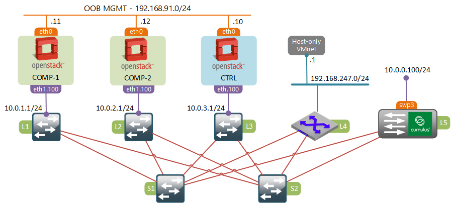
To simulate the baremetal server (10.0.0.100) I’ve VRF’d an interface on Arista “L4” switch and connected it directly to a “swp3” interface of the Cumulus VX. This is not shown on the diagram.
Solution overview
L2 Gateway is a relatively new service plugin for OpenStack Neutron. It provides the ability to interconnect a given tenant network with a VLAN on a physical switch. There are three main components that compose this solution:
- Hardware switch implementing the OVSDB hardware vtep schema. This is a special “flavour” of OVSDB designed specifically to enable connectivity between logical (VXLAN VTEP) and physical (switchport) interfaces.
- L2GW agent running on a network node. This is the process responsible for connecting to OVSDB server running on a hardware switch and updating that database based on instructions received from a L2GW service plugin.
- L2GW Service Plugin residing on a control node. The task of this plugin is to notify the L2GW agent and normal L2 OVS agents running on compute hosts about network events and distribute VTEP IP address information between them.
Note that in our case both network and control nodes are running on the same VM.
Cumulux VX configuration
Cumulux is a debian-based linux distribution, therefore most of the basic networking configuration will be similar to how things are done in Ubuntu. First, let’s start by configuring basic IP addressing on Loopback (VTEP IP), Eth0 (OOB management), swp1 and swp2 (fabric) interfaces.
iface lo inet loopback
        address 10.0.0.5/32

auto eth0
iface eth0 inet static
        address 192.168.91.21/24

auto swp1
iface swp1 inet static
        address 169.254.51.5/24

auto swp2
iface swp2 inet static
        address 169.254.52.5/24

auto swp3
iface swp3
Next, let’s enable OSPF
sudo sed -i s/zebra=no/zebra=yes/ /etc/quagga/daemons
sudo sed -i s/ospfd=no/ospfd=yes/ /etc/quagga/daemons
sudo service quagga restart
Once OSPFd is running, we can use sudo vtysh to connect to local quagga shell and finalise the configuration.
interface lo
 ip ospf area 0.0.0.0
 link-detect
!
interface swp1
 ip ospf area 0.0.0.0
 ip ospf network point-to-point
 link-detect
!
interface swp2
 ip ospf area 0.0.0.0
 ip ospf network point-to-point
 link-detect
!
router ospf
 ospf router-id 10.0.0.5
 passive-interface default
 no passive-interface swp1
 no passive-interface swp2
At this stage our Cumulus VX switch should be fully adjacent to both spines and its loopback IP (10.0.0.5) should be reachable from all OpenStack nodes.
The final step is to enable the hardware VTEP functionality. The process is fairly simple and involves only a few commands.
$ sudo sed -i s/START=no/START=yes/g /etc/default/openvswitch-vtep
$ sudo service openvswitch-vtep start
$ sudo vtep-bootstrap L5 10.0.0.5 192.168.91.21 --no_encryption
The last command runs a bootstrap script that does the following things:
- Creates a hardware VTEP OVSDB schema
- Inside that schema creates a new physical switch called “L5”
- Sets the VTEP IP to 10.0.0.5
- Starts listening to incoming OVSDB connections on 192.168.91.21
Hardware VTEP vs OpenvSwitch OVSDB schemas (Optional)
By now you’re probably wondering what’s that hardware VTEP OVSDB schema and how it’s different from a normal OVS schema. First of all, remember that OVSDB is just a database and OVSDB protocol is just a set of JSON RPC calls to work with that database. Information that can be stored in the database is defined by a schema - a structure that represents tables and their relations. Therefore, OVSDB can be used to store and manage ANY type of data which makes it very flexible. Specificallly OVS project defines two OVSDB schemas:
- Open_vSwitch schema - used to manage bridges, ports and controllers of OpenvSwitch. This schema is used by OVS inside every compute host we have in our OpenStack environment.
- Hardware_vtep schema - designed to be used by physical switches. The goal of this schema is to extend the virtual L2 switch into a physical realm by providing the ability to map physical ports to logical networks. For each logical network the hardware VTEP database holds mappings of MAC addresses to VTEPs and physical switchport.
The information from these databases is later consumed by another process that sets up the actual bridges and ports. The first schema is used by the ovs-vswitchd process running on all compute hosts to configure ports and flows of integration and tunnel bridges. In case of a Cumulus switch, the information from hardware_vtep OVSDB is used by a process called ovs-vtepd that is responsible for settings up VXLAN VTEP interfaces, provisioning of VLANs on physical switchports and interconnecting them with a Linux bridge.
If you want to learn more, check out this awesome post about hardware VTEP and OVS.
OpenStack Control node configuration
Most of the following procedure has been borrowed from another blog. It’s included it this post because I had to do some modifications and also for the sake of completeness.
-
Clone the L2GW repository
git clone -b stable/mitaka https://github.com/openstack/networking-l2gw.git -
Use pip to install the plugin
pip install ./networking-l2gw/ -
Enable the L2GW service plugin
sudo sed -ri 's/^(service_plugins.*)/1,networking_l2gw.services.l2gateway.plugin.L2GatewayPlugin/' /etc/neutron/neutron.conf -
Copy L2GW configuration files into the neutron configuration directory
cp /usr/etc/neutron/l2g* /etc/neutron/ -
Point the L2GW plugin to our Cumulus VX switch
sudo sed -ri "s/^#s+(ovsdb_hosts).*/1 = 'ovsdb1:192.168.91.21:6632'/" /etc/neutron/l2gateway_agent.ini -
Update Neutron database with the new schema required by L2GW plugin
systemctl stop neutron-server neutron-db-manage --config-file /etc/neutron/neutron.conf --config-file /etc/neutron/l2gw_plugin.ini upgrade head systemctl start neutron-server -
Update Neutron startup script to load the L2GW plugin configuration file
sed -ri "s/(ExecStart=.*)/1 --config-file /etc/neutron/l2gw_plugin.ini /" /usr/lib/systemd/system/neutron-server.service -
Create a L2GW systemd unit file
cat >> /usr/lib/systemd/system/neutron-l2gateway-agent.service << EOF [Unit] Description=OpenStack Neutron L2 Gateway Agent After=neutron-server.service [Service] Type=simple User=neutron ExecStart=/usr/bin/neutron-l2gateway-agent --config-file /etc/neutron/neutron.conf --config-file /etc/neutron/l2gateway_agent.ini KillMode=process [Install] WantedBy=multi-user.target EOF -
Restart both L2GW and neutron server
systemctl daemon-reload systemctl restart neutron-server.service systemctl start neutron-l2gateway-agent.service -
Enter the “neutron configuration mode”
source ~/keystone_admin neutron -
Create a new L2 gateway device
l2-gateway-create --device name="L5",interface_names="swp3" CUMULUS-L2GW -
Create a connection between a “private_network” and a native vlan (dot1q 0) of swp3 interface
l2-gateway-connection-create --default-segmentation-id 0 CUMULUS-L2GW private_network
Verification and Traffic Flows
At this stage everything should be ready for testing. We’ll start by examining the following traffic flow:
- From VM-2 10.0.0.4 / fa:16:3e:d7:0e:14
- To baremetal server 10.0.0.100 / 50:00:00:6b:2e:70
The communication starts with VM-2 sending an ARP request for the MAC address of the baremetal server. Packet flow inside the compute host will be exactly the same as before, with packet being flooded from the VM to the integration and tunnel bridges. Inside the tunnel bridge the packet gets resubmitted to table 22 where head-end replication of ARP request takes place.
The only exception is that this time the frame will get replicated to a new VXLAN port pointing towards the Cumulux VTEP IP. We’ll use the ovs-appctl ofproto/trace command to see the full path a packet takes inside OVS, which is similar to packet-tracer command of Cisco ASA. To simulate an ARP packet we need to specify the incoming port(in_port), EtherType(arp), internal VLAN number for our tenant(dl_vlan) and an ARP request target IP address(arp_tpa). You can find the full list of fields that can be matched in this document.
$ ovs-appctl ofproto/trace br-tun in_port=1,arp,dl_vlan=1,arp_tpa=10.0.0.100 | grep -E "Rule|actions="
Rule: table=0 cookie=0xb3c018296c2aa8a3 priority=1,in_port=1
OpenFlow actions=resubmit(,2)
Rule: table=2 cookie=0xb3c018296c2aa8a3 priority=0,dl_dst=00:00:00:00:00:00/01:00:00:00:00:00
OpenFlow actions=resubmit(,20)
Rule: table=20 cookie=0xb3c018296c2aa8a3 priority=0
OpenFlow actions=resubmit(,22)
Rule: table=22 cookie=0xb3c018296c2aa8a3 dl_vlan=1
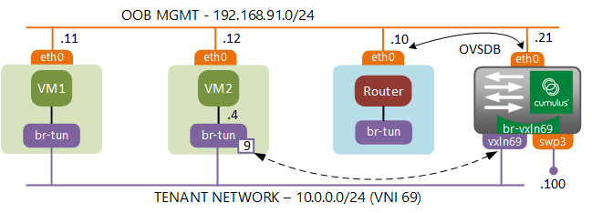
OpenFlow actions=strip_vlan,set_tunnel:0x45,output:9,output:4,output:6
The packet leaving port 9 will get encapsulated into a VXLAN header with destination IP of 10.0.0.5 and forwarded out the fabric-facing interface eth1.100. When VXLAN packet reaches the vxln69 interface (10.0.0.5) of the Cumulus switch, the br-vxlan69 Linux bridge floods the frame out the second connected interface - swp3.
$ brctl show br-vxln69
bridge name        bridge id          STP enabled     interfaces
br-vxln69          8000.500000070003  no              swp3
                                                      vxln69
The rest of the story is very simple. When ARP packet hits the baremetal server it populates its ARP cache. A unicast response travels all the way back to the Cumulus switch, gets matched by the static MAC (0e:14) entry created based on information provided by the L2GW plugin. This entry points to the VTEP IP of Compute host 2(10.0.2.10) which is where it gets forwarded next.
$ bridge fdb show
50:00:00:09:00:04 dev swp3 vlan 0 master br-vxln69
50:00:00:07:00:03 dev swp3 vlan 0 master br-vxln69 permanent
50:00:00:6b:2e:70 dev swp3 vlan 0 master br-vxln69
26:21:90:a8:8a:cc dev vxln69 vlan 0 master br-vxln69 permanent
fa:16:3e:57:1c:6c dev vxln69 dst 10.0.3.10 vlan 65535 self permanent
fa:16:3e:a4:12:e6 dev vxln69 dst 10.0.3.10 vlan 65535 self permanent
fa:16:3e:d7:0e:14 dev vxln69 dst 10.0.2.10 vlan 65535 self permanent
fa:16:3e:3c:51:d7 dev vxln69 dst 10.0.1.10 vlan 65535 self permanent
The packet travels through compute host 2, populating the flow entries of all OVS bridges along the way. These entries are then used by subsequent unicast packets travelling from VM-2.
$ ovs-appctl ofproto/trace br-tun in_port=1,dl_vlan=1,dl_dst=50:00:00:6b:2e:70 | grep -E "Rule|actions="
Rule: table=0 cookie=0xb5625033061a8ae5 priority=1,in_port=1
OpenFlow actions=resubmit(,2)
        Rule: table=2 cookie=0xb5625033061a8ae5 priority=0,dl_dst=00:00:00:00:00:00/01:00:00:00:00:00
        OpenFlow actions=resubmit(,20)
                Rule: table=20 cookie=0xb5625033061a8ae5 priority=1,vlan_tci=0x0001/0x0fff,dl_dst=50:00:00:6b:2e:70
                OpenFlow actions=load:0->NXM_OF_VLAN_TCI[],load:0x45->NXM_NX_TUN_ID[],output:9
It all looks fine until the ARP cache of the baremetal server expires and you get an ARP request coming from the physical into the virtual world. There is a known issue with BUM forwarding which requires a special service node to perform the head-end replication. The idea is that a switch that needs to flood a multicast packet, would send it to a service node which keeps track of all active VTEPs in the network and performs packet replication on behalf of the sender. OpenStack doesn’t have a dedicated service node, however it is possible to trick the network node into performing a similar functionality, which is what I’m going to demonstrate next.
Programming Network Node as BUM replication service node
First of all, we need to tell our Cumulus switch to send all multicast packets to the network node. To do that we need to modify OVSDB table called “Mcast_Macs_Remote”. You can view the contents of the database using the ovsdb-client dump --pretty tcp:192.168.91.21:6632 command to make sure that this table is empty. Using the VTEP control command we need to force all unknown-dst (BUM) traffic to go to the network node(10.0.3.10). The UUID of the logical switch can be found with sudo vtep-ctl list-ls command.
sudo vtep-ctl add-mcast-remote 818b4779-645c-49bb-ae4a-aa9340604019 unknown-dst 10.0.3.10
At this stage all BUM traffic hits the network node and gets flooded to the DHCP and the virtual router namespaces. In order to force this traffic to also be replicated to all compute nodes we can use some of the existing tables of the tunnel bridge. Before we do anything let’s have a look at the tables our ARP request has to go through inside the tunnel bridge.
table=0, priority=1,in_port=2 actions=resubmit(,4)
table=4, priority=1,tun_id=0x45 actions=mod_vlan_vid:1,resubmit(,10)
table=10,priority=1 actions=learn(table=20,hard_timeout=300,priority=1,cookie=0x9f3e746b7ee48bbf,NXM_OF_VLAN_TCI[0..11],NXM_OF_ETH_DST[]=NXM_OF_ETH_SRC[],load:0->NXM_OF_VLAN_TCI[],load:NXM_NX_TUN_ID[]->NXM_NX_TUN_ID[],output:NXM_OF_IN_PORT[]),output:1
We also have a default head-end replication table 22 which floods all BUM traffic received from the integration bridge to all VTEPs:
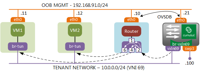
table=22, dl_vlan=1 actions=strip_vlan,set_tunnel:0x45,output:2,output:4,output:6
So what we can do is create a new flow entry that would intercept all ARP packets inside Table 4 and resubmit them to tables 10 and 22. Table 10 will take our packet up to the integration bridge of the network node, since we still need to be able to talk the virtual router and the DHCP. Table 22 will receive a copy of the packet and flood it to all known VXLAN endpoints.
ovs-ofctl add-flow br-tun "table=4,arp,tun_id=0x45,priority=2,actions=mod_vlan_vid:1,resubmit(,10),resubmit(,22)"
We can once again use the trace command to see the ARP request flow inside the tunnel bridge.
$ ovs-appctl ofproto/trace br-tun in_port=2,arp,tun_id=0x45 | grep -E "Rule|actions="
Rule: table=0 cookie=0x9f3e746b7ee48bbf priority=1,in_port=2
OpenFlow actions=resubmit(,4)
        Rule: table=4 cookie=0 priority=2,arp,tun_id=0x45
        OpenFlow actions=mod_vlan_vid:1,resubmit(,10),resubmit(,22)
                Rule: table=10 cookie=0x9f3e746b7ee48bbf priority=1
                OpenFlow actions=learn(table=20,hard_timeout=300,priority=1,cookie=0x9f3e746b7ee48bbf,NXM_OF_VLAN_TCI[0..11],NXM_OF_ETH_DST[]=NXM_OF_ETH_SRC[],load:0->NXM_OF_VLAN_TCI[],load:NXM_NX_TUN_ID[]->NXM_NX_TUN_ID[],output:NXM_OF_IN_PORT[]),output:1
                        Rule: table=0 cookie=0x91b1a9a9b6e8d608 priority=0
                        OpenFlow actions=NORMAL
                                Rule: table=0 cookie=0xb36f6e358a37bea6 priority=2,in_port=2
                                OpenFlow actions=drop
                Rule: table=22 cookie=0x9f3e746b7ee48bbf dl_vlan=1
                OpenFlow actions=strip_vlan,set_tunnel:0x45,output:2,output:4,output:6
Now we should be able to clear the ARP cache on baremetal device and successfully ping both VM-2, VM-1 and the virtual router.
Conclusion
The workaround presented above is just a temporary solution for the problem. In order to fix the problem properly, OVS vtep schema needs to be updated to support source node replication. Luckily, the patch implementing this functionality has been merged into master OVS branch only a few days ago. So hopefully, this update trickles down to Cumulus package repositories soon.
Despite all the issues, Neutron L2 gateway plugin is a cool project that provides a very important piece of functionality without having to rely on 3rd party SDN controllers. Let’s hope it will continue to be supported and developed by the community.
Coming up
In the next post I was planning to examine another “must have” feature of any SDN solution - Distributed Virtual Routing. However due to my current circumstances I may need to take a few weeks break before going on. Be back soon!