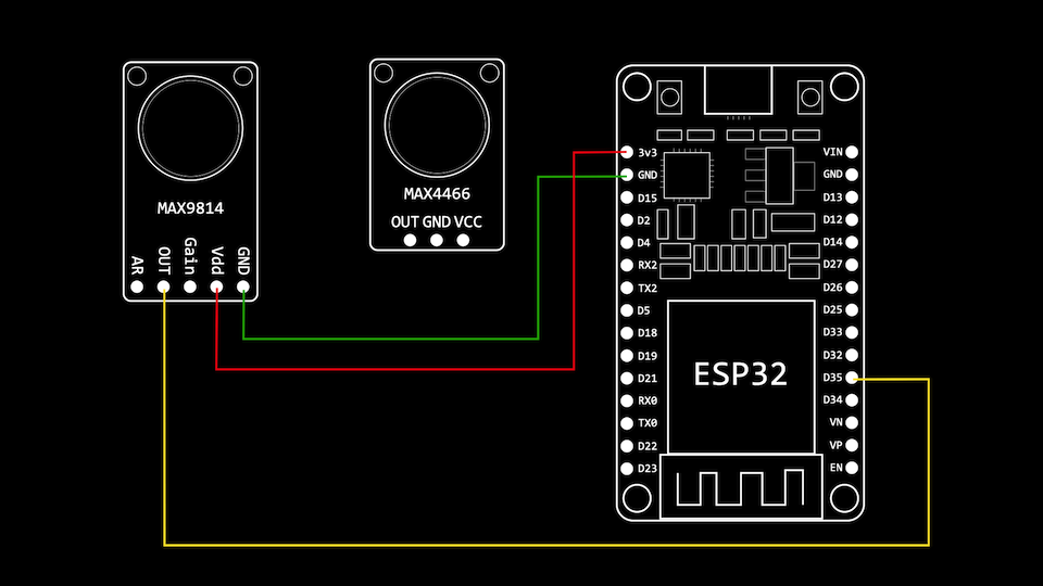
有几种方法可以将模拟音频数据输入到ESP32中。
- 直接从内置的模数转换器(ADC)读取
- 这对于一次性读取很有用,但不适用于高采样率。
- 使用I2S通过DMA读取内置ADC
- 适用于模拟麦克风,例如MAX4466和MAX9814
- 使用I2S直接从I2S兼容外设读取
- 对于SPH0645LM4H,INPM441,ICS43432和ICS43434等麦克风有用
直接从ADC读取
ESP32上有两个内置ADC,ADC1和ADC2。
ADC1具有8个通道:
| 渠道 | 通用输入输出 | 渠道 | 通用输入输出 |
|---|---|---|---|
| ADC1_CHANNEL_0 | GPIO36 | ADC1_CHANNEL_4 | GPIO32 |
| ADC1_CHANNEL_1 | GPIO37 | ADC1_CHANNEL_5 | GPIO33 |
| ADC1_CHANNEL_2 | GPIO38 | ADC1_CHANNEL_6 | GPIO34 |
| ADC1_CHANNEL_3 | GPIO39 | ADC1_CHANNEL_7 | GPIO35 |
ADC2有10个通道:
| 渠道 | 通用输入输出 | 渠道 | 通用输入输出 |
|---|---|---|---|
| ADC2_CHANNEL_0 | GPIO4 | ADC2_CHANNEL_5 | GPIO12 |
| ADC2_CHANNEL_1 | GPIO0 | ADC2_CHANNEL_6 | GPIO14 |
| ADC2_CHANNEL_2 | GPIO2 | ADC2_CHANNEL_7 | GPIO27 |
| ADC2_CHANNEL_3 | GPIO15 | ADC2_CHANNEL_8 | GPIO25 |
| ADC2_CHANNEL_4 | GPIO13 | ADC2_CHANNEL_9 | GPIO26 |
尽管有一些限制-WiFi子系统也使用ADC2,并且某些引脚还用于控制启动行为的捆绑引脚。这意味着在项目中坚持使用ADC1是最安全的。
从ADC读取非常简单-您可以使用Arduino函数或直接使用Espressif函数:
// read using Arduino
int sample = analogRead(35)

// read using Espressif
int sample = adc1_get_raw(ADC1_CHANNEL_7);
ESP32 ADC非常不准确,如果您想获得准确的读数,可以使用校准设置。现在,这些操作大多在工厂完成,因此您的ESP32应该已经具有一些校准设置。也可以手动校准ADC。
要读取校准值,请使用以下代码,它将为您提供以毫伏为单位的值。这两个调用adc1_config_width和adc1_config_channel_atten是至关重要的,因为校准特性需要匹配ADC配置。
// calibration values for the adc
#define DEFAULT_VREF 1100
esp_adc_cal_characteristics_t *adc_chars;

//Range 0-4096
adc1_config_width(ADC_WIDTH_BIT_12);

// full voltage range
adc1_config_channel_atten(ADC1_CHANNEL_7, ADC_ATTEN_DB_11);

// get the ADC characteristics
esp_adc_cal_characterize(
  ADC_UNIT_1,
  ADC_ATTEN_DB_11,
  ADC_WIDTH_BIT_12,
  DEFAULT_VREF,
  adc_chars);

// read a sample from the ADC
int sample = adc1_get_raw(ADC1_CHANNEL_7);

// get the calibrated value
int milliVolts = esp_adc_cal_raw_to_voltage(sample, adc_chars);
使用I2S和DMA的高速ADC采样
直接使用ADC可以进行低频和一次性采样。为了采样高质量的音频数据,您将需要以16-40KHz的频率采样。您可以使用计时器来执行此操作,但这并不是ESP32的CPU资源的最佳用途。
更好的方法是使用内置的I2S外设将ADC的样本直接读取到内存中。
这是使用I2S读取内置ADC的基本设置。
i2s_config_t i2s_config = {
    .mode = (i2s_mode_t)(I2S_MODE_MASTER | I2S_MODE_RX | I2S_MODE_ADC_BUILT_IN),
    .sample_rate = 40000,
    .bits_per_sample = I2S_BITS_PER_SAMPLE_16BIT,
    .channel_format = I2S_CHANNEL_FMT_ONLY_LEFT,
    .communication_format = I2S_COMM_FORMAT_I2S_LSB,
    .intr_alloc_flags = ESP_INTR_FLAG_LEVEL1,
    .dma_buf_count = 2,
    .dma_buf_len = 1024,
    .use_apll = false,
    .tx_desc_auto_clear = false,
    .fixed_mclk = 0};

//install and start i2s driver
i2s_driver_install(I2S_NUM_0, &i2s_config, 4, &i2s_queue);

//init ADC pad
i2s_set_adc_mode(ADC_UNIT_1, ADC1_CHANNEL_7);

// enable the ADC
i2s_adc_enable(I2S_NUM_0);

// start a task to read samples from I2S
TaskHandle_t readerTaskHandle;
xTaskCreatePinnedToCore(readerTask, "Reader Task", 8192, this, 1, &readerTaskHandle, 0);
然后,您可以使用以下任务从ADC读取样本:
void readerTask(void *param)
{
    I2SSampler *sampler = (I2SSampler *)param;
    while (true)
    {
        // wait for some data to arrive on the queue
        i2s_event_t evt;
        if (xQueueReceive(sampler->i2s_queue, &evt, portMAX_DELAY) == pdPASS)
        {
            if (evt.type == I2S_EVENT_RX_DONE)
            {
                size_t bytesRead = 0;
                do
                {
                    // try and fill up our audio buffer
                    size_t bytesToRead = (ADC_SAMPLES_COUNT - sampler->audioBufferPos) * 2;
                    void *bufferPosition = (void *)(sampler->currentAudioBuffer + sampler->audioBufferPos);
                    // read from i2s
                    i2s_read(I2S_NUM_0, bufferPosition, bytesToRead, &bytesRead, 10 / portTICK_PERIOD_MS);
                    sampler->audioBufferPos += bytesRead / 2;
                    if (sampler->audioBufferPos == ADC_SAMPLES_COUNT)
                    {
                        // do something with the sample - e.g. notify another task to do some processing
                   }
                } while (bytesRead > 0);
            }
        }
    }
}
阅读完样本后,您可以执行所需的任何处理,I2S外设将在后台继续将样本从ADC读取到DMA缓冲区中。
MA4466的接线非常简单,只需将VCC连接至3v3,将GND连接至GND,将Out连接至与您要从其采样的ADC通道相对应的GPIO引脚。

尝试MAX9814的方法相同-您也可以通过将增益引脚连接至VCC或GND来发挥MAX9814的增益。

原文地址:https://blog.cmgresearch.com/2020/09/12/esp32-audio-input.html