延迟计算
Delay Calculation
要找到时序路径的裕量,分析工具必须确定发射时钟边沿的到达时间、捕获时钟边沿的到达时间,以及从路径的起点到端点的延迟。为了找到发射时钟边沿的到达时间,该工具计算从原始源时钟到发射触发器的时钟输入端的延迟。类似地,为了找到捕获时钟边沿的到达时间,该工具计算从原始源时钟到捕获触发器的时钟输入端的延迟。它还考虑到时钟的周期,若如果发射和捕获时钟不同,还需要考虑这些时钟之间的最坏偏移。
To find the slack for a timing path, the analysis tool must determine the arrival time of the launch clock edge, the arrival time of the capture clock edge, and the delay from the startpoint to the endpoint of the path. To find the arrival time of the launch clock edge, the tool calculates the delay from the original source clock to the clock input of the launch flip-flop. Similarly, to find the arrival time of the capture clock edge, the tool calculates the delay from the original source clock to the clock input of the capture flip-flop. It also considers the period of the clock, or if the launch and capture clocks are different, the worst-case offset between those clocks.
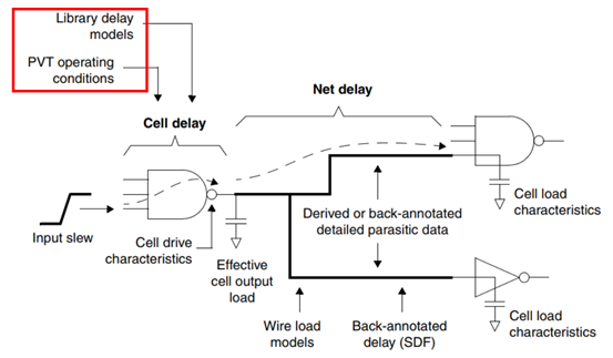
为了找到沿着时序路径的累积延迟,分析工具将沿着路径的单个单元延迟和互连延迟相加。单元延迟信息包含在每个单元的库描述中。计算互连线的延迟,分析工具需要知道驱动网络的驱动单元的特性,驱动网络的接收单元的负载特性,以及网络中连线的电阻和电容(RC)的特性。互连线的RC特性取决于连线的物理结构和长度,因此只有在布线完成后才能准确地确定这些特性。
To find the cumulative delay along a path, the analysis tool adds the individual cell delays and interconnect delays along the path. The cell delay information is contained in the library description of each cell. To calculate the interconnect delays, the analysis tool needs to know the characteristics of the driver cell that is driving the net, the load characteristics of the receiver cells driven by the net, and the resistance and capacitance (RC) characteristics of the wires in the net. The interconnect RC characteristics depend on the physical configuration and lengths of the wires, so these characteristics can be determined accurately only after layout has been completed.
对于在布局和布线之前执行的时间分析,分析工具必须估计连线延迟。最简单的估计方法是线负载模型,它根据芯片的大小和网外扇的大小得到导线总电容的粗略值。更大的芯片尺寸和较大的扇出值会导致更长的连线,更多的电阻与电容。更先进的线估计方法预测单元的位置和线的长度,从而在不使用线负载模型的情况下得到更准确的结果。
For timing analysis performed before placement and routing, the analysis tool must estimate the wire delays. The simplest estimation method is the wire load model, which gets a rough value for the total wire capacitance based on the size of the chip and the fanout of the net.Larger chip sizes and larger fanouts are assumed to result in longer wires and more resistance and capacitance. More advanced wire estimation methods predict cell placement and wire lengths, thereby getting more accurate results without using wire load models.
带有拓扑分析技术的DC就是这样一种高级工具。对于放置和布线后进行的时序分析,分析工具可以从导线连接的物理长度和已知的导线材料特性中精确地提取RC网络信息。例如,ICC可以精确地从可用的细节布线或从细节布线尚未完成的全局布线提取RC信息。
Design Compiler with topographical technology is one such advanced tool.For timing analysis performed after placement and routing, the analysis tool can extract the RC network accurately from the physical lengths of the wire connections and the known characteristics of the wire material. IC Compiler, for example, extracts RC information accurately from detail routing when available or from global routing where detail routing has not been completed.
在延迟计算中主要用到的信息类型如图1-12所示
The main types of information used in delay calculation are summarized in Figure 1-12.
图1-12 在单元与网表延迟计算中使用的信息
Figure 1-12 Information Used in Cell and Net Delay Calculation
您可以使用report_delay_calculation命令查看单元或网络的延迟计算的详细结果。
You can view a detailed accounting of the delay calculation for a cell or a net by using the report_delay_calculation command.

触发器和锁存器时序检查
Flip-Flop and Latch Timing Checks
在触发器和基于锁存器的设计之间,检查建立时间和保持时间的方法有一些不同。对于边缘敏感型触发器,在时钟边缘到达触发器时,数据必须严格可用。而对于电平敏感锁存器,若从一个锁存器"借用"时间到下一个锁存器,则可以放松某些路径的时序要求。图1-13显示了时序分析工具如何检查基于触发器的同步时序设计的建立和保持时间约束。
The method of checking setup and hold timing differs somewhat between flip-flop and latch-based designs. For edge-sensitive flip-flops, the data must be available strictly at the time that the clock edge arrives at the flip-flop. For level-sensitive latches, "borrowing" time from one latch to the next can loosen the timing requirements for certain paths.Figure 1-13 shows how a timing analysis tool checks setup and hold constraints for a synchronous design based on flip-flops.
图1-13 建立时间和保持时间检查
Figure 1-13 Setup and Hold Checks
对于本例,假设在工艺库中定义了触发器,其最小建立时间为1.0时间单位,最小保持时间为0.0时间单位。时钟周期由create_clock命令定义为10个时间单位。时间单位大小,例如ns或ps,是在工艺库中指定的。
For this example, assume that the flip-flops are defined in the technology library to have a minimum setup time of 1.0 time units and a minimum hold time of 0.0 time units. The clock period is defined by the create_clock command to be 10 time units. The time unit size, such as ns or ps, is specified in the technology library.
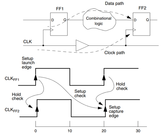
默认情况下,该(时序检查)工具假设信号将在一个时钟周期内在路径传播。当该工具执行建立时间检查时,它验证如下情况是否成立:从FF1发射的数据在一个时钟周期内到达FF2,并且在数据相对于下一个时钟边缘捕获至少提前到达1.0个时间单位。如果路径延迟太长,它被报告为时序违例。对于该项建立时间检查,(时序检查)工具主要考虑FF1和FF2之间的数据路径的最长可能延迟和FF1与FF2之间时钟路径的最短可能延迟。
By default, the tool assumes that the signal is to be propagated through the path in one clock cycle. When the tool performs a setup check, it verifies that the data launched from FF1 reaches FF2 within one clock cycle and arrives at least 1.0 time unit before the data gets captured by the next clock edge at FF2. If the path delay is too long, it is reported as a timing violation. For this setup check, the tool considers the longest possible delay along the data path and the shortest possible delay along the clock path between FF1 and FF2.
当工具执行一个保持时间检查时,它检查从FF1发射的数据到达FF2的时间不会比前一个时钟周期的捕获时钟边沿到来的时间早。这个检查确保已经存在于FF2输入端的数据在捕获上一个周期数据的时钟边缘之后保持足够长时间的稳定。对于这个保持时间检查,工具会考虑FF1和FF2之间沿数据路径可能的最短延迟和沿时钟路径可能的最长延迟。如果时钟路径有较长的延迟,则会发生保持时间冲突。
When the tool performs a hold check, it verifies that the data launched from FF1 reaches FF2 no sooner than the capture clock edge for the previous clock cycle. This check ensures that the data that already exists at the input of FF2 remains stable long enough after the clock edge that captures data for the previous cycle. For this hold check, the tool considers the shortest possible delay along the data path and the longest possible delay along the clock path between FF1 and FF2. A hold violation can occur if the clock path has a long delay.
基于锁存器的设计通常使用两阶段的、不重叠的时钟来控制数据路径中的连续寄存器。在这些情况下,工具可以使用时间借用来减少连续路径上的约束。例如,考虑图1-14所示的基于锁存器的两阶段路径。所有三个锁存器都是电平敏感的,当G输入高时,gate端有效。L1和L3由PH1控制,L2由PH2控制。上升沿使得锁存器输出端发射数据,下降沿在锁存器输入端捕获数据。对于这个示例,考虑锁存器建立时间和延迟时间为零。
Latch-based designs typically use two-phase, nonoverlapping clocks to control successive registers in a data path. In these cases, the tool can use time borrowing to lessen the constraints on successive paths.For example, consider the two-phase, latch-based path shown in Figure 1-14. All three latches are level-sensitive, with the gate active when the G input is high. L1 and L3 are controlled by PH1, and L2 is controlled by PH2. A rising edge launches data from the latch output, and a falling edge captures data at the latch input. For this example, consider the latch setup and delay times to be zero.
图1-14 基于锁存器的路径
Figure 1-14 Latch-Based Paths
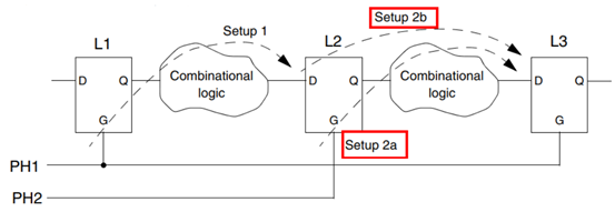
图1-15显示了该工具如何在这些锁存器之间执行建立时间检查。对于L1到L2的路径,PH1的上升沿发射数据。数据必须在PH2的下降沿(此时时间为20单位)之前到达L2。这个时间要求标记为Setup 1。根据L1和L2之间的延迟大小,在时间等于10单位时,数据在PH2的上升沿之前或之后到达都有可能,如时间图中标记为"到达a"和"到达b"的虚线箭头所示。在时间超过20(单位)后达到将造成时序违例。
Figure 1-15 shows how the tool performs setup checks between these latches. For the path from L1 to L2, the rising edge of PH1 launches the data. The data must arrive at L2 before the closing edge of PH2 at time = 20. This timing requirement is labeled Setup 1. Depending on the amount of delay between L1 and L2, the data might arrive either before or after the opening edge of PH2 at time = 10, as indicated by the dashed-line arrows labeled "Arrival a"and "Arrival b" in the timing diagram. Arrival after time = 20 would be a timing violation.
图1-15 锁存器路径上的时间借用
Figure 1-15 Time Borrowing in Latch-Based Paths
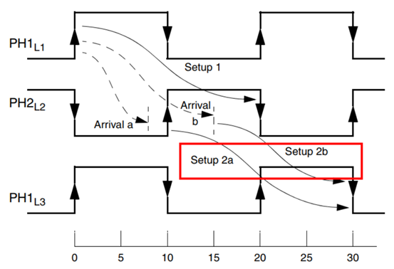
如果数据在时间为10时到达L2,此时PH2的上升沿还没有到达(到达a情况),那么经过L2到L3的下一条路径的数据就会在时间等于10时由PH2的上升边发射,如同一个同步触发器一样工作。在这种情况下,没有向第二条途径借用时间。L2至L3的时间要求被标记为Setup 2a。如果数据到达PH2的上升边之后(到达b情况),则第一条路径(L1到L2)需要从第二条路径借用时间(从L2到L3)。在这种情况下,第二条路径的数据发射发生在数据到达时间L2,在PH2的上升沿与下降沿之间的某一时刻。这个时间要求标记为Setup 2b。当时间借用发生时,路径起始于L2的D引脚,而不是G引脚。对于从L1到L2的路径,如果出现时间借用,该工具报告建立时间裕量为零。
If the data arrives at L2 before the opening edge of PH2 at time = 10 (Arrival a), the data for the next path from L2 to L3 gets launched by the opening edge of PH2 at time = 10, just as a synchronous flip-flop would operate. In this case, no time is borrowed from the second path. This timing requirement for L2 to L3 is labeled Setup 2a. If the data arrives after the opening edge of PH2 (Arrival b), the first path (from L1 to L2) borrows time from the second path (from L2 to L3). In that case, the launch of data for the second path occurs at the data arrival time at L2, at some time between the opening and closing edges of PH2. This timing requirement is labeled Setup 2b. When borrowing occurs, the path originates at the D pin, rather than the G pin, of L2. For the path from L1 to L2, the tool reports the setup slack as zero if borrowing occurs.
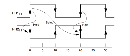
如果数据在t=10上升沿边缘前已经到达,则时间裕量为正。如果数据在t=20下降沿边缘后达到,则时间裕量是负的(时序违例)。为了执行保持时间检查,工具会考虑相对于建立时间的发射和捕获边沿。它检查在起始点发射的数据不会太快到达端点,从而确保上一个周期启动的数据被锁存,不会被新数据覆盖。如图1-16显示。
The slack is positive if the data arrives before the opening edge at time = 10, or it is negative (a violation) if the data arrives after the closing edge at time = 20. To perform hold checking, the tool considers the launch and capture edges relative to the setup check. It verifies that data launched at the startpoint does not reach the endpoint too quickly, thereby ensuring that data launched in the previous cycle is latched and not overwritten by the new data. This is depicted in Figure 1-16.
图1-16基于锁存器路径的保持时间检查
Figure 1-16 Hold Checks in Latch-Based Paths