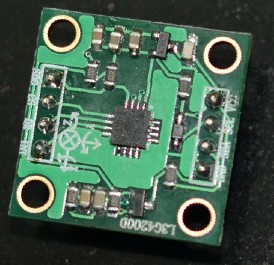
L3G4200D陀螺仪有点贵,好像要130左右,我买了散件回来自己焊接的,居然一次焊成功了,以前重来没焊过贴片工艺的板子,L3G4200D芯片太小了,不用镊子都拿不出,回想一下焊接过程还真的是很惊险刺激。来张焊好的作品:

其实这个板子和一个一元硬币差不多大,焊接手法还不错吧,哈。。
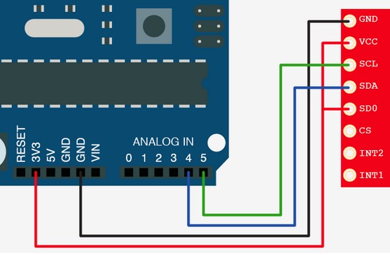
和ANDRIOD接线方式如下:

测试代码:
#include <Wire.h>
#define CTRL_REG1 0x20
#define CTRL_REG2 0x21
#define CTRL_REG3 0x22
#define CTRL_REG4 0x23
#define CTRL_REG5 0x24
int L3G4200D_Address = 105; //I2C address of the L3G4200D
int x;
int y;
int z;
void setup(){
Wire.begin();
Serial.begin(9600);
Serial.println("starting up L3G4200D");
setupL3G4200D(2000); // Configure L3G4200 - 250, 500 or 2000 deg/sec
delay(1500); //wait for the sensor to be ready
}
void loop(){
getGyroValues(); // This will update x, y, and z with new values
Serial.print("X:");
Serial.print(x);
Serial.print(" Y:");
Serial.print(y);
Serial.print(" Z:");
Serial.println(z);
delay(100); //Just here to slow down the serial to make it more readable
}
void getGyroValues(){
byte xMSB = readRegister(L3G4200D_Address, 0x29);
byte xLSB = readRegister(L3G4200D_Address, 0x28);
x = ((xMSB << 8) | xLSB);
byte yMSB = readRegister(L3G4200D_Address, 0x2B);
byte yLSB = readRegister(L3G4200D_Address, 0x2A);
y = ((yMSB << 8) | yLSB);
byte zMSB = readRegister(L3G4200D_Address, 0x2D);
byte zLSB = readRegister(L3G4200D_Address, 0x2C);
z = ((zMSB << 8) | zLSB);
}
int setupL3G4200D(int scale){
//From Jim Lindblom of Sparkfun's code
// Enable x, y, z and turn off power down:
writeRegister(L3G4200D_Address, CTRL_REG1, 0b00001111);
// If you'd like to adjust/use the HPF, you can edit the line below to configure CTRL_REG2:
writeRegister(L3G4200D_Address, CTRL_REG2, 0b00000000);
// Configure CTRL_REG3 to generate data ready interrupt on INT2
// No interrupts used on INT1, if you'd like to configure INT1
// or INT2 otherwise, consult the datasheet:
writeRegister(L3G4200D_Address, CTRL_REG3, 0b00001000);
// CTRL_REG4 controls the full-scale range, among other things:
if(scale == 250){
writeRegister(L3G4200D_Address, CTRL_REG4, 0b00000000);
}else if(scale == 500){
writeRegister(L3G4200D_Address, CTRL_REG4, 0b00010000);
}else{
writeRegister(L3G4200D_Address, CTRL_REG4, 0b00110000);
}
// CTRL_REG5 controls high-pass filtering of outputs, use it
// if you'd like:
writeRegister(L3G4200D_Address, CTRL_REG5, 0b00000000);
}
void writeRegister(int deviceAddress, byte address, byte val) {
Wire.beginTransmission(deviceAddress); // start transmission to device
Wire.write(address); // send register address
Wire.write(val); // send value to write
Wire.endTransmission(); // end transmission
}
int readRegister(int deviceAddress, byte address){
int v;
Wire.beginTransmission(deviceAddress);
Wire.write(address); // register to read
Wire.endTransmission();
Wire.requestFrom(deviceAddress, 1); // read a byte
while(!Wire.available()) {
// waiting
}
v = Wire.read();
return v;
}
upload到andriod就可以通过COM口查看陀螺仪的测量结果了:
starting up L3G4200D
X:5 Y:0 Z:6
X:6 Y:1 Z:6
X:3 Y:1 Z:6
X:0 Y:2 Z:7
X:6 Y:0 Z:6
X:3 Y:0 Z:10
X:2 Y:0 Z:9
X:1 Y:0 Z:7
X:3 Y:3 Z:6
X:1 Y:0 Z:9
X:4 Y:1 Z:9
X:9 Y:1 Z:8
X:3 Y:1 Z:7
X:6 Y:1 Z:6
X:4 Y:1 Z:11
X:8 Y:0 Z:10
X:8 Y:0 Z:8
X:6 Y:1 Z:11
X:6 Y:1 Z:8
X:8 Y:1 Z:11
X:2 Y:0 Z:7
X:1 Y:1 Z:10
X:6 Y:1 Z:4
X:7 Y:1 Z:9
X:5 Y:2 Z:9
X:4 Y:9 Z:-5
X:14 Y:-5 Z:30
X:4 Y:0 Z:7
X:2 Y:0 Z:0
X:8 Y:0 Z:8
X:4 Y:0 Z:12
X:3 Y:1 Z:9
X:5 Y:2 Z:9
X:5 Y:0 Z:6
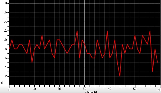
从结果看陀螺仪静止状态下数据还是有点跳动,这样就需要滤波,我准备配合加速度传感器利用卡尔曼滤波的方法来实现,目前尚在测试过程中。
下面是陀螺仪静止放在桌面上的Z轴角速度波形图:

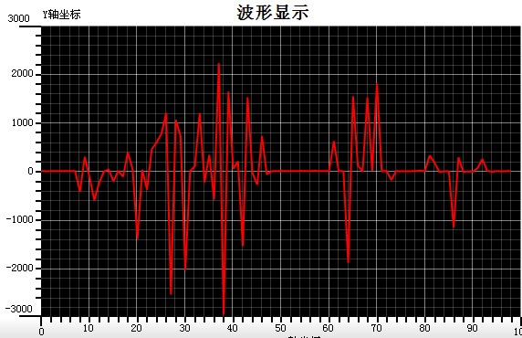
陀螺仪运动中:

陀螺仪数据处理
陀螺仪的直接输出值是相对灵敏轴的角速率,角速率对时间积分即可得到围绕灵敏轴旋转过的角度值。由于系统采用微控制器循环采样程序获取陀螺仪角速率信息,即每隔一段很短的时间采样一次,所以采用累加的方法实现积分的功能来计算角度值:

公式中angle n为陀螺仪采样到第n次的角度值;angle (n-1)为陀螺仪第n-1次采样时的角度值;gyro n 为陀螺仪的第n次采样得到的瞬时角速率值;dt为主运行一遍所用时间。可见,用陀螺仪输出值积分计算角度,要求处理器运算速度足够快,采样程序应尽量简练,程序循环一遍所用时间dt越小,采样频率越高,最后积分得到的角度值才能越精确。
陀螺仪是用来测量角速度信号的,通过对角速度积分,能得到角度值。但由于温度变化、摩擦力和不稳定力矩等因素,陀螺仪会产成漂移误差。而无论多么小的常值漂移通过积分都会得到无限大的角度误差。因而,也不能单独使用陀螺仪作为本机器人倾角传感器。