- 工程的main.c函数如下.
1: /*
2: 头文件包含
3: */
4: #include "lpc12xx_libcfg.h"
5:
6: /*********************************************************************************************************
7: 宏定义
8: *********************************************************************************************************/
9: #define LED_PORT LPC_GPIO1 /* LED引脚端口P1 */
10: #define LED_PINS 2 /* LED引脚P1.2 */
11:
12: /*********************************************************************************************************
13: 全局变量定义
14: *********************************************************************************************************/
15: static uint16_t GusGPIO1Port[7] = { /* GPIO1端口引脚类型 */
16: IOCON_PIO_1_0,
17: IOCON_PIO_1_1,
18: IOCON_PIO_1_2,
19: IOCON_PIO_1_3,
20: IOCON_PIO_1_4,
21: IOCON_PIO_1_5,
22: IOCON_PIO_1_6
23: };
24:
25: void myDelay (uint32_t ulTime) //软件延时
26: {
27: uint32_t i = 0;
28:
29: while (ulTime--) {
30: for (i = 0; i < 5000; i++);
31: }
32: }
33:
34: void ledOn (void) // 点亮LED(输出低电平)
35: {
36: GPIO_SetLowLevel(LED_PORT, LED_PINS, ENABLE); /* 输出低电平,点亮LED */
37: }
38:
39:
40: void ledOff (void)//Descriptions: 熄灭LED(输出高电平)
41: {
42: GPIO_SetHighLevel(LED_PORT, LED_PINS, ENABLE); /* 输出高电平,熄灭LED */
43: }
44:
45:
46: void ledInit (void) //Descriptions: LED初始化
47: {
48: IOCON_PIO_CFG_Type PIO_mode;
49:
50: IOCON_StructInit(&PIO_mode); /* 初始化端口模式 */
51: PIO_mode.type = GusGPIO1Port[LED_PINS];
52: IOCON_SetFunc(&PIO_mode); /* 设置LED引脚为GPIO功能 */
53:
54: GPIO_SetDir(LED_PORT, LED_PINS, GPIO_DIR_OUTPUT); /* 设置LED引脚为输出 */
55:
56: ledOff(); /* 熄灭LED */
57: }
58:
59:
60: int main (void) // 运行程序,观察LED1状态.LED1以约200ms为周期闪烁
61: {
62: SystemInit(); /* 系统时钟初始化 */
63: SYS_ConfigAHBCLK(SYS_AHBCLKCTRL_IOCON, ENABLE); /* IOCON模块使能 */
64: SYS_ConfigAHBCLK(SYS_AHBCLKCTRL_GPIO1, ENABLE); /* GPIO1时钟使能 */
65:
66: ledInit(); /* LED初始化 */
67:
68: while(1) {
69: ledOn();
70: myDelay(100);
71: ledOff();
72: myDelay(200);
73: }
74: }
75:
76: #ifdef DEBUG
77: /*********************************************************************************************************
78: ** Function name: check_failed
79: ** Descriptions:
80: ** input parameters: 无
81: ** output parameters: 无
82: ** Returned value: 无
83: *********************************************************************************************************/
84: void check_failed (uint8_t *file, uint32_t line)
85: {
86: while(1); /* Infinite loop */
87: }
88: #endif
一.程序总体流程:
- 系统时钟初始化:
- IOCON模块使能
- GPIO1时钟使能
- LED初始化
- 死循环:灯闪烁(一亮一灭)
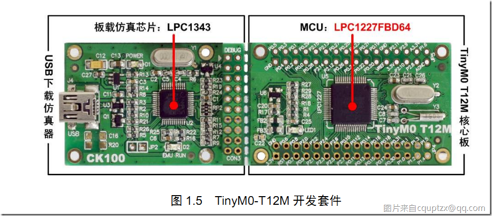
二.硬件实物图:
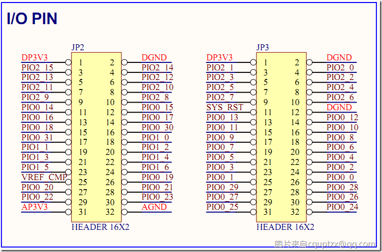
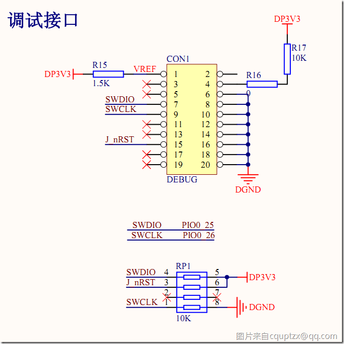
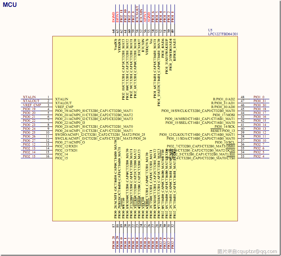
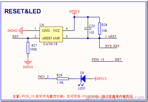
三.硬件原理图
文件位置(E:\kpan\Desktop\LPC\硬件原理图TinyM0_T12_ku\TinyM0 T12M原理图与器件封装库\TinyM0 T12M原理图)
(原理图下载地址:【硬件资料】TinyM0 T12(M)原理图与器件封装库 [出处 2-25 2418次])
LED引脚的定义:
在main.c中有,
#define LED_PORT LPC_GPIO1 /* LED引脚端口P1 */
#define LED_PINS 2 /* LED引脚P1.2 */
在lpc12xx.h中有,
#define LPC_GPIO1 ((LPC_GPIO_TypeDef *) LPC_GPIO1_BASE )
#define LPC_GPIO2_BASE (LPC_AHB_BASE + 0x20000)
#define LPC_AHB_BASE (0x50000000UL)
这样就可以对引脚P1.2进行寻址了.
附:
在,(0x50000000UL) 中UL的意思是: unsigned long int.
四.部分程序解释
(1)全局变量的定义.
static uint16_t GusGPIO1Port[7] = { /* GPIO1端口引脚类型 */
IOCON_PIO_1_0,
IOCON_PIO_1_1,
IOCON_PIO_1_2,
IOCON_PIO_1_3,
IOCON_PIO_1_4,
IOCON_PIO_1_5,
IOCON_PIO_1_6
};
在lpc_12xxiocon.h中有,
#define IOCON_PIO_1_0 ((uint16_t)0x0BC1 ) /* PIO port1 type definition */
2013年3月30日 00:30:12
2013年3月30日 10:49:59
(2)
SystemInit();
系统初始化函数,在system_lpc12xx.c中
(3)
SYS_ConfigAHBCLK(SYS_AHBCLKCTRL_IOCON, ENABLE); /* IOCON模块使能 */
SYS_ConfigAHBCLK(SYS_AHBCLKCTRL_GPIO1, ENABLE); /* GPIO1时钟使能 */
系统_配置外围模块时钟的使能,在Lpc12xx_syscrtl.c中
1: /**
2: * @brief 使能或者禁止系统和外围时钟.
3: Disable or enable system and peripheral clock.
4: *
5: * @param AHBClk_Type: 外围模块时钟类型,AHB clock type.
6: * @param CmdState:使能/禁止 Enable or disable the clock for System or
7: * peripheral blocks.
8: * This parameter can be ENABLE or DISABLE.
9: * @retval None.
10: */
11: void SYS_ConfigAHBCLK(uint32_t AHBClk_Type, FunctionalState CmdState)
12: {
13: if(CmdState) LPC_SYSCON->SYSAHBCLKCTRL |= AHBClk_Type;
14: else LPC_SYSCON->SYSAHBCLKCTRL &= ~(AHBClk_Type);
15: }
(4)
GPIO_SetLowLevel(LED_PORT, LED_PINS, ENABLE); /* 输出低电平,点亮LED */
GPIO_SetHighLevel(LED_PORT, LED_PINS, ENABLE); /* 输出高电平,熄灭LED */
设置GPIO口为高电平还是低电平,(根据原理图,低电平点亮LED)
在Lpc12xx_gpio.c中,
1: /**
2: * @brief Set Value for bits that have output direction on GPIO port.
3: 设置GPIO端口的输出值.
4: * @param pGPIO LPC_GPIOn 哪个GPIO
5: Port Number selection, should be LPC_GPIO0, LPC_GPIO1, LPC_GPIO2
6: * @param bitPosi n 哪个引脚号
7: bit position value, should be from 0 to 31, if it is oxff, set 'value'
8: * @param value 值:0/1
9: if bitPosi is from 0 to 31, Direction value, should be:
10: * - 0: no effect
11: * - 1: high level.
12: * if bitPosi is oxff, set the all 32-bits of register
13: * @return None
14: *
15: * Note:
16: * - For all bits that has been set as input direction, this function will
17: * not effect.
18: * - For all remaining bits that are not activated in bitValue (value '0')
19: * will not be effected by this function.
20: */
21: void GPIO_SetHighLevel(LPC_GPIO_TypeDef* pGPIO, uint8_t bitPosi, uint32_t value)
22: {
23: CHECK_PARAM(PARAM_GPIOx(pGPIO));
24:
25: gpio_setvalue((uint32_t *)&pGPIO->SET, bitPosi, value);
26: }
27:
28: /**
29: * @brief Clear Value for bits that have output direction on GPIO port.
30: * @param pGPIO Port Number selection, should be LPC_GPIO0, LPC_GPIO1, LPC_GPIO2
31: * @param bitPosi bit position value, should be from 0 to 31, if it is oxff, set 'value'
32: * @param value if bitPosi is from 0 to 31, Direction value, should be:
33: * - 0: No effect.
34: * - 1: low level.
35: * if bitPosi is oxff, set the all 32-bits of register
36: * @return None
37: *
38: * Note:
39: * - For all bits that has been set as input direction, this function will
40: * not effect.
41: * - For all remaining bits that are not activated in bitValue (value '0')
42: * will not be effected by this function.
43: */
44: void GPIO_SetLowLevel(LPC_GPIO_TypeDef* pGPIO, uint8_t bitPosi, uint32_t value)
45: {
46: CHECK_PARAM(PARAM_GPIOx(pGPIO));
47:
48: gpio_setvalue((uint32_t *)&pGPIO->CLR, bitPosi, value);
49: }
- 在这里的CHECK_PARM用于检查某个函数的参数检查,在Lpc12xx_libcfg.h中有,
1: #ifdef DEBUG
2: /*******************************************************************************
3: * @brief 这个函数用于某个函数的参数检查,只在DEBUG模式下编译时使用.
4: * The CHECK_PARAM macro is used for function's parameters check.
5: * It is used only if the library is compiled in DEBUG mode.
6: * @param[in] 表达式,如果表达式为假,调用参数检查失败(check_failed.)函数
7: * expr - If expr is false, it calls check_failed() function
8: * which reports the name of the source file and the source
9: * line number of the call that failed.
10: * - If expr is true, it returns no value.
11: * @return None
12: *******************************************************************************/
13: #define CHECK_PARAM(expr) ((expr) ? (void)0 : check_failed((uint8_t *)__FILE__, __LINE__))
14: #else
15: #define CHECK_PARAM(expr)
16: #endif /* DEBUG */
1: #define PARAM_GPIOx(n) ((((uint32_t *)n)==((uint32_t *)LPC_GPIO0)) || \
2: (((uint32_t *)n)==((uint32_t *)LPC_GPIO1)) || \
3: (((uint32_t *)n)==((uint32_t *)LPC_GPIO2)))
4:
5: volatile uint32_t GPIOShadowPort[3];
这里的关键是调用了这个函数:
1:
2: /**
3: * @brief Set GPIO register.
4: * @param pGPIO LPC_GPIOn Port Number selection, should be LPC_GPIO0, LPC_GPIO1, LPC_GPIO2
5: * @param offset 寄存器的偏移值 Register offset value.
6: * @param bitPosi 操作比特位/直接设置值 bit position value, should be from 0 to 31, if it is oxff, set 'value'
7: * @param value 如果操作比特位,那么值为0/1
8: * if bitPosi is from 0 to 31, Direction value, should be:
9: * - 0: no mask.
10: * - 1: mask.
11: * if bitPosi is oxff, set the all 32-bits of register
12: * @return None
13: *
14: * Note: All remaining bits that are not activated in bitValue (value '0')
15: * will not be effected by this function.
16: */
17: static void gpio_setvalue(uint32_t *p, uint8_t bitPosi, uint32_t value)
18: {
19: CHECK_PARAM(( bitPosi < 0x20 ) || ( bitPosi == 0xFF ));
20: CHECK_PARAM(( value == 0 ) || ( value == 1 ));
21:
22: if(bitPosi < 0x20){
23: if (value) {
24: *(uint32_t *)p |= (0x1<<bitPosi);
25: }
26: else {
27: *(uint32_t *)p &= ~(0x1<<bitPosi);
28: }
29: }
30: else if(bitPosi == 0xFF){
31: *(uint32_t *)p = value;
32: }
33: }
调用关系:
GPIO_SetLowLevel(LED_PORT, LED_PINS, ENABLE); LedOn() main.c
|-CHECK_PARAM(PARAM_GPIOx(pGPIO));
|-gpio_setvalue((uint32_t *)&pGPIO->CLR, bitPosi, value);
(5)设置IOCON_PIOn_m的值
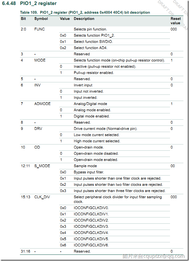
LED引脚的寄存器 在 E:\kpan\Desktop\LPC\LPC1200系列微控制器产品数据手册(英) LPC1200_ds_en page112页.
6.4.48 PIO1_2 register
(6)LED初始化函数
void ledInit (void)
{
IOCON_PIO_CFG_Type PIO_mode;IOCON_StructInit(&PIO_mode); /* 初始化端口模式 */
PIO_mode.type = GusGPIO1Port[LED_PINS];
IOCON_SetFunc(&PIO_mode); /* 设置LED引脚为GPIO功能 */GPIO_SetDir(LED_PORT, LED_PINS, GPIO_DIR_OUTPUT); /* 设置LED引脚为输出 */
ledOff(); /* 熄灭LED */
}
分析:
第一句,IOCON_PIO_CFG_Type PIO_mode;定义了一个IO引脚配置的结构体,描述了上面的 6.4.48 PIO1_2 register 的值.
typedef struct {
uint16_t type; /*!< low 8 bits is address offset, other is func >
This parameter can be a value of @ref PIO_type */
uint8_t pinmode; /*!< Pin mode >
This parameter can be a value of @ref PIO_pin_mode */
uint8_t invert; /*!< Inverted function >
This parameter can be a value of @ref Invert_input_mode */
uint8_t ad; /*!< analog/digital mode >
This parameter can be a value of @ref Analog_digital_mode */
uint16_t pmode; /*!< Push/pull mode for I2C >
This parameter can be a value of @ref Push_Pull_mode */
uint16_t od; /*!< Open drive >
This parameter can be a value of @ref Open_drain_mode */
uint16_t drive; /*!< Pin driver function >
This parameter can be a value of @ref Drive_current_mode */
uint16_t sm; /*!< Sample mode >
This parameter can be a value of @ref Sample_mode */
uint32_t cd; /*!< Clock Divider >
This parameter can be a value of @ref clock_divider_num */
} IOCON_PIO_CFG_Type;
第二句,IOCON_StructInit(&PIO_mode); 使用默认值来初始化了结构体.
void IOCON_StructInit ( IOCON_PIO_CFG_Type *mode)
{
mode->type = 0x0;
mode->pinmode = IOCON_PIO_MODE_PULLUP;
mode->invert = IOCON_PIO_INV_NOT;
mode->pmode = IOCON_PIO_PMODE_DISABLE;
mode->od = IOCON_PIO_OD_DISABLE;
mode->drive = IOCON_PIO_DRV_2MA_12MA;
mode->ad = IOCON_PIO_AD_DIGITAL;
mode->sm = IOCON_PIO_SMODE_BYPASS;
mode->cd = IOCON_PIO_CLKDIV_0;
}
第三句,PIO_mode.type = GusGPIO1Port[LED_PINS];设置结构体的type成员的值
PIO_mode.type = GusGPIO1Port[LED_PINS];
LED_PINS=2,那么根据定义的数组
static uint16_t GusGPIO1Port[7] = { /* GPIO1端口引脚类型 */
IOCON_PIO_1_0,
IOCON_PIO_1_1,
IOCON_PIO_1_2,
IOCON_PIO_1_3,
IOCON_PIO_1_4,
IOCON_PIO_1_5,
IOCON_PIO_1_6
};
有PIO_mode.type =IOCON_PIO_1_2 ,
根据宏定义
#define IOCON_PIO_1_2 ((uint16_t)0x0C40 )
所以,最后有,IO引脚结构体type成员变量为
PIO_mode.type=0x0C40
第四句,IOCON_SetFunc(&PIO_mode); /* 设置LED引脚为GPIO功能 */
根据结构体指针来设置引脚的功能
void IOCON_SetFunc ( IOCON_PIO_CFG_Type *mode)
{
uint32_t offset;
uint32_t func;
uint32_t tmp;
uint32_t *p = (uint32_t *)&LPC_IOCON->PIO2_28;CHECK_PARAM( PARAM_IOCON_PIO_TYPE(mode->type) );
CHECK_PARAM( PARAM_IOCON_PIO_MODE(mode->pinmode));
CHECK_PARAM( PARAM_IOCON_PIO_DRV(mode->drive) );
CHECK_PARAM( PARAM_IOCON_PIO_AD(mode->ad) );
CHECK_PARAM( PARAM_IOCON_PIO_OD(mode->od));
CHECK_PARAM( PARAM_IOCON_PIO_INV(mode->invert) );
CHECK_PARAM( PARAM_IOCON_PIO_SMODE(mode->sm));
CHECK_PARAM( PARAM_IOCON_PIO_CLKDIV(mode->cd));offset = (mode->type >> 6);
func = (mode->type & 0xf);if(offset == 0x24 || offset == 0x25){ //0x90, 0x94 right shift 2 bit
tmp = (uint32_t)(func|(mode->pmode)|(mode->od)|(mode->invert)|(mode->sm)|(mode->cd));}else{
tmp = (uint32_t)(func|(mode->pinmode)|(mode->drive)|(mode->ad)|(mode->od)|(mode->invert)|(mode->sm)|(mode->cd));
}
*(uint32_t *)(p + offset) = tmp;
}
第五句,GPIO_SetDir(LED_PORT, LED_PINS, GPIO_DIR_OUTPUT); 设置端口方向,输出
/**
* @brief Set Direction for GPIO port.
* @param pGPIO Port Number selection, should be LPC_GPIO0, LPC_GPIO1, LPC_GPIO2
* @param bitPosi bit position value, should be from 0 to 31, if it is oxff, set 'value'
* @param value if bitPosi is from 0 to 31, Direction value, should be:
* - 0: Input.
* - 1: Output.
* if bitPosi is oxff, set the all 32-bits of register
* @return None
*
* Note: All remaining bits that are not activated in bitValue (value '0')
* will not be effected by this function.
*/
void GPIO_SetDir(LPC_GPIO_TypeDef* pGPIO, uint8_t bitPosi, uint32_t value)
{
CHECK_PARAM(PARAM_GPIOx(pGPIO));gpio_setvalue((uint32_t *)&pGPIO->DIR, bitPosi, value);
}
第六句,LedOff(),灯灭.
2013年3月30日 17:13:44
