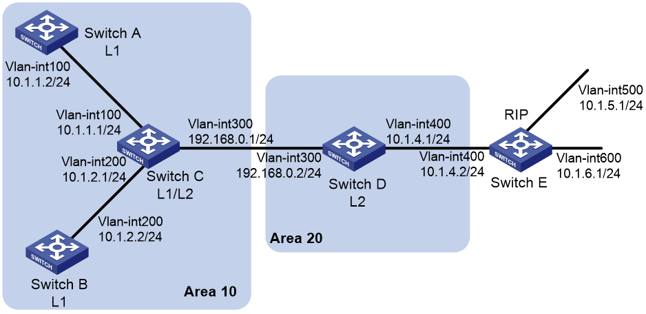
1.组网需求
· Switch A、Switch B、Switch C和Switch D属于同一自治系统,要求它们之间通过IS-IS协议达到IP网络互连的目的。
· Switch A和Switch B为Level-1路由器,Switch D为Level-2路由器,Switch C作为Level-1-2路由器将两个区域相连。Switch A、Switch B和Switch C的区域号为10,Switch D的区域号为20。
· 在Switch D的IS-IS进程中引入RIP路由。

2.配置步骤
1)配置各接口和IS-IS基本功能
2)在Switch D和Switch E之间运行RIPv2,在Switch D上配置IS-IS进程引入RIP路由。
# 在Switch D上配置RIPv2。

[SwitchD] rip 1
[SwitchD-rip-1] network 10.0.0.0
[SwitchD-rip-1] version 2
[SwitchD-rip-1] undo summary

# 在Switch E上配置RIPv2。
[SwitchE] rip 1
[SwitchE-rip-1] network 10.0.0.0
[SwitchE-rip-1] version 2
[SwitchE-rip-1] undo summary

# 在Switch D上配置IS-IS进程引入RIP进程的路由。
[SwitchD] isis 1
[SwitchD–isis-1] address-family ipv4
[SwitchD–isis-1-ipv4] import-route rip level-2
# 显示Switch C的IS-IS路由信息。
[SwitchC] display isis route
                         Route information for IS-IS(1)
                         ------------------------------
                         Level-1 IPv4 Forwarding Table
                         -----------------------------
 IPv4 Destination     IntCost    ExtCost ExitInterface   NextHop         Flags
-------------------------------------------------------------------------------
 10.1.1.0/24          10         NULL    VLAN100         Direct          D/L/-
 10.1.2.0/24          10         NULL    VLAN200         Direct          D/L/-
 192.168.0.0/24       10         NULL    VLAN300         Direct          D/L/-

      Flags: D-Direct, R-Added to Rib, L-Advertised in LSPs, U-Up/Down Bit Set

                         Level-2 IPv4 Forwarding Table
                         -----------------------------
 IPv4 Destination     IntCost    ExtCost ExitInterface   NextHop         Flags
-------------------------------------------------------------------------------
 10.1.1.0/24          10         NULL                                    D/L/-
 10.1.2.0/24          10         NULL                                    D/L/-
 192.168.0.0/24       10         NULL                                    D/L/-
 10.1.4.0/24          20         NULL    VLAN300         192.168.0.2     R/L/-
 10.1.5.0/24          10         0       VLAN300         192.168.0.2     R/L/-
 10.1.6.0/24          10         0       VLAN300         192.168.0.2     R/L/-
      Flags: D-Direct, R-Added to Rib, L-Advertised in LSPs, U-Up/Down Bit Set