直流电机调速仿真作业
block Controller
InPort command(n=1);
InPort feedback(n=1);
OutPort outPort(n=1);
Real error;
Real pout;
parameter Real Kp=10;
parameter Real Max_Output_Pos = 10;
parameter Real Max_Output_Neg = -10;
// parameter Real Ki=1;
algorithm
error := command.signal[1] - feedback.signal[1];
pout := Kp * error;
if pout > Max_Output_Pos then
outPort.signal[1] := Max_Output_Pos;
elseif pout < Max_Output_Neg then
outPort.signal[1] := Max_Output_Neg;
else
outPort.signal[1] := pout;
end if;
end Controller;
在题目模型比例调节控制器基础上增加积分调节和微分调节组合为PID控制器,修改代码如下:
block Controller
InPort command(n=1);
InPort feedback(n=1);
OutPort outPort(n=1);
Real error;
Real errori;
Real errord;
Real pout;
parameter Real Kp=7;
parameter Real Ki=0.1;
parameter Real Kd=50;
parameter Real Max_Output_Pos = 10;
parameter Real Max_Output_Neg = -10;
algorithm
error := command.signal[1] - feedback.signal[1];
errori:=errori+error;
errord:=error-pre(error);
pout := Kp * error+Ki*errori+Kd*errord;
if pout > Max_Output_Pos then
outPort.signal[1] := Max_Output_Pos;
elseif pout < Max_Output_Neg then
outPort.signal[1] := Max_Output_Neg;
else
outPort.signal[1] := pout;
end if;
end Controller;
PID三个调节参数对动态响应的影响为:
Kp增大会减小电流值达到稳定的时间,但会增大超调量,降低系统稳定性;
Ki消除稳态误差,但会降低系统稳定性,减慢动态响应;
Kd能减小超调量,减小调节时间;
根据Kp,Ki,Kd三个参数的调节特性,在保证较小的调节时间下尽量减小超调量,依次选取调节Kp,Ki,Kd三个参数,调节Kp值保证调节时间较短但超调量不可过大,调节Ki消除电机电流和电机速度达到稳定后的稳态误差而尽量减少对动态响应速度的减慢效应,调节Kd值减小超调量和调节时间。最终选取PID调节参数为Kp=7,Ki=0.1,Kd=50
最终得到的电机电流与电机速度变化曲线如下:

为方便从图中读出电机电流调节时间和最大超调量,将模型仿真时间缩短为1.5s
simulate( DCMotorControlSystem, stopTime=1.5)
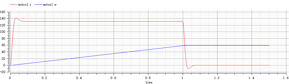
由图可得到最大超调量为9.23%,电机电流调节时间为0.08s,动态响应的最大超调量与调节时间均很小,同时没有稳态调节误差
完整代码如下:
type ElectricPotential = Real;
type ElectricCurrent = Real(quantity = "ElectricCurrent", unit = "A");
type Resistance = Real(quantity = "Resistance", unit = "Ohm", min = 0);
type Inductance = Real(quantity = "Inductance", unit = "H", min = 0);
type Voltage = ElectricPotential;
type Current = ElectricCurrent;
type Force = Real(quantity = "Force", unit = "N");
type Angle = Real(quantity = "Angle", unit = "rad", displayUnit = "deg");
type Torque = Real(quantity = "Torque", unit = "N.m");
type AngularVelocity = Real(quantity = "AngularVelocity", unit = "rad/s", displayUnit = "rev/min");
type AngularAcceleration = Real(quantity = "AngularAcceleration", unit = "rad/s2");
type MomentOfInertia = Real(quantity = "MomentOfInertia", unit = "kg.m2");
type Time = Real (final quantity="Time", final unit="s");
connector RotFlange_a "1D rotational flange (filled square)"
Angle phi "Absolute rotational angle of flange";
flow Torque tau "Torque in the flange";
end RotFlange_a; //From Modelica.Mechanical.Rotational.Interfaces
connector RotFlange_b "1D rotational flange (filled square)"
Angle phi "Absolute rotational angle of flange";
flow Torque tau "Torque in the flange";
end RotFlange_b; //From Modelica.Mechanical.Rotational.Interfaces
connector Pin "Pin of an electrical component"
Voltage v "Potential at the pin";
flow Current i "Current flowing into the pin";
end Pin; //From Modelica.Electrical.Analog.Interfaces
connector PositivePin "Positive pin of an electrical component"
Voltage v "Potential at the pin";
flow Current i "Current flowing into the pin";
end PositivePin; //From Modelica.Electrical.Analog.Interfaces
connector NegativePin "Negative pin of an electrical component"
Voltage v "Potential at the pin";
flow Current i "Current flowing into the pin";
end NegativePin; //From Modelica.Electrical.Analog.Interfaces
connector InPort "Connector with input signals of type Real"
parameter Integer n = 1 "Dimension of signal vector";
input Real signal[n] "Real input signals";
end InPort; // From Modelica.Blocks.Interfaces
connector OutPort "Connector with output signals of type Real"
parameter Integer n = 1 "Dimension of signal vector";
output Real signal[n] "Real output signals";
end OutPort; // From Modelica.Blocks.Interfaces
partial model Rigid // Rotational class Rigid
"Base class for the rigid connection of two rotational 1D flanges"
Angle phi "Absolute rotation angle of component";
RotFlange_a rotFlange_a "(left) driving flange (axis directed into plane)";
RotFlange_b rotFlange_b "(right) driven flange (axis directed out of plane)";
equation
rotFlange_a.phi = phi;
rotFlange_b.phi = phi;
end Rigid; // From Modelica.Mechanics.Rotational.Interfaces
model Inertia "1D rotational component with inertia"
extends Rigid;
parameter MomentOfInertia J = 1 "Moment of inertia";
AngularVelocity w "Absolute angular velocity of component";
AngularAcceleration a "Absolute angular acceleration of component";
equation
w = der(phi);
a = der(w);
J*a = rotFlange_a.tau + rotFlange_b.tau;
end Inertia; //From Modelica.Mechanics.Rotational
partial model TwoPin // Same as OnePort in Modelica.Electrical.Analog.Interfaces
"Component with two electrical pins p and n and current i from p to n"
Voltage v "Voltage drop between the two pins (= p.v - n.v)";
Current i "Current flowing from pin p to pin n";
PositivePin p;
NegativePin n;
equation
v = p.v - n.v;
0 = p.i + n.i;
i = p.i;
end TwoPin;
model DCMotor "DC Motor"
extends TwoPin;
extends Rigid;
OutPort SensorVelocity(n=1);
OutPort SensorCurrent(n=1);
parameter MomentOfInertia J"Total Inertia";
parameter Resistance R"Armature Resistance";
parameter Inductance L"Armature Inductance";
parameter Real Kt"Torque Constant";
parameter Real Ke"EMF Constant";
AngularVelocity w "Angular velocity of motor";
AngularAcceleration a "Absolute angular acceleration of motor";
Torque tau_motor;
RotFlange_b rotFlange_b; // Rotational Flange_b
equation
w = der(rotFlange_b.phi);
a = der(w);
v = R*i+Ke*w+L*der(i);
tau_motor = Kt*i;
J*a = tau_motor + rotFlange_b.tau;
SensorVelocity.signal[1] = w;
SensorCurrent.signal[1] = i;
end DCMotor;
class Resistor "Ideal linear electrical Resistor"
extends TwoPin; // Same as OnePort
parameter Real R(unit = "Ohm") "Resistance";
equation
R*i = v;
end Resistor; // From Modelica.Electrical.Analog.Basic
class Inductor "Ideal linear electrical Inductor"
extends TwoPin; // Same as OnePort
parameter Real L(unit = "H") "Inductance";
equation
v = L*der(i);
end Inductor; // From Modelica.Electrical.Analog.Basic
class Ground "Ground node"
Pin p;
equation
p.v = 0;
end Ground; // From Modelica.Electrical.Analog.Basic
model PWMVoltageSource
extends TwoPin;
InPort Command(n=1);
parameter Time T = 0.003;
parameter Voltage Vin = 200;
equation
T*der(v)+ v = Vin*Command.signal[1]/10;
end PWMVoltageSource;
block Controller
InPort command(n=1);
InPort feedback(n=1);
OutPort outPort(n=1);
Real error;
Real errori;
Real errord;
Real pout;
parameter Real Kp=7;
parameter Real Ki=0.1;
parameter Real Kd=50;
parameter Real Max_Output_Pos = 10;
parameter Real Max_Output_Neg = -10;
algorithm
error := command.signal[1] - feedback.signal[1];
errori:=errori+error;
errord:=error-pre(error);
pout := Kp * error+Ki*errori+Kd*errord;
if pout > Max_Output_Pos then
outPort.signal[1] := Max_Output_Pos;
elseif pout < Max_Output_Neg then
outPort.signal[1] := Max_Output_Neg;
else
outPort.signal[1] := pout;
end if;
end Controller;
block CommandSignalGenerator
OutPort outPort(n=1);
Real acc;
equation
if time <= 1 then
acc =60;
elseif time <3 then
acc = 0;
elseif time <4 then
acc = -60;
else
acc = 0;
end if;
der(outPort.signal[1]) = acc;
end CommandSignalGenerator;
model PWMVoltageSource
extends TwoPin;
InPort Command(n=1);
parameter Time T = 0.003;
parameter Voltage Vin = 200;
equation
T*der(v)+ v = Vin*Command.signal[1]/10;
end PWMVoltageSource;
model DCMotor "DC Motor"
extends TwoPin;
extends Rigid;
OutPort SensorVelocity(n=1);
OutPort SensorCurrent(n=1);
parameter MomentOfInertia J"Total Inertia";
parameter Resistance R"Armature Resistance";
parameter Inductance L"Armature Inductance";
parameter Real Kt"Torque Constant";
parameter Real Ke"EMF Constant";
AngularVelocity w "Angular velocity of motor";
AngularAcceleration a "Absolute angular acceleration of motor";
Torque tau_motor;
RotFlange_b rotFlange_b; // Rotational Flange_b
equation
w = der(rotFlange_b.phi);
a = der(w);
v = R*i+Ke*w+L*der(i);
tau_motor = Kt*i;
J*a = tau_motor + rotFlange_b.tau;
SensorVelocity.signal[1] = w;
SensorCurrent.signal[1] = i;
end DCMotor;
block CommandSignalGenerator
OutPort outPort(n=1);
Real acc;
equation
if time <= 1 then
acc =60;
elseif time <3 then
acc = 0;
elseif time <4 then
acc = -60;
else
acc = 0;
end if;
der(outPort.signal[1]) = acc;
end CommandSignalGenerator;
model DCMotorControlSystem
Ground ground1;
Inertia inertia1(J = 3, w(fixed = true));
DCMotor motor1(J = 1,R = 0.6,L = 0.01,Kt=1.8, Ke= 1.8,rotFlange_b(phi(fixed = true)));
CommandSignalGenerator sg1;
Controller con1;
PWMVoltageSource PowerSource1;
equation
connect(sg1.outPort, con1.command);
connect(con1.feedback, motor1.SensorVelocity);
connect(con1.outPort, PowerSource1.Command);
connect(PowerSource1.p, motor1.p);
connect(motor1.rotFlange_b, inertia1.rotFlange_a);
connect(PowerSource1.n, ground1.p);
connect(ground1.p, motor1.n);
end DCMotorControlSystem;
simulate( DCMotorControlSystem, stopTime=5)
plot({motor1.i,motor1.w})