目標
因為對 device tree 不是很熟悉,
所以就將 device tree,
設為學習目標。
啟動
注意,
這篇隨筆的解說都放在最下面,會標 Explanation_XX,只要搜尋 Explanation_XX 往上找,就可以看到 source code 要解說的點,
總之就是多找幾遍,如 Explanation_13,就會出現 source code 及 解說。
那要如何開始呢?
從 spec?
從 公司的案子 Uxxxxxx 的 device tree code 開始,
kernel-3.18/arch/arm64/boot/dts/mtXX.dtsi
   1 /*
   2  * Mediatek's MTXXXX SoC device tree source
   3  *
   4  * Copyright (c) 2013 MediaTek Co., Ltd.
   5  *              http://www.mediatek.com
   6  *
   7  */
   8
   ...
   ...
   ...
   3178 #include "mtXXXX.dtsi"
   3179 #else
   3180 #include "mtXXXX.dtsi"
   3181 #endif
3千多行,
oh! my god!
換個平台好了!
順道一提,
*.dts 是 device tree source code,
*.dtsi 是常用的 device tree source code,類似 c 語言的 .h,
*.dtb (b : blob)是 device tree source code 編譯後的二進制檔,
*.dts 及 *.dtsi 可以看到 device tree source code,
也可以將 *.dtb decompile 成 device tree source code,
$ ./out/target/product/project_name/obj/KERNEL_OBJ/scripts/dtc/dtc -I dtb -O dts -o decompiled.dts ~/project/linux_repo/out/target/product/project_name/obj/KERNEL_OBJ/arch/arm64/boot/dts/your.dtb
也就是
kernel-3.18/out/***/scripts/dtc/dtc -I dtb -O dts -o you_want.dts your.dtb
Usage: dtc [options] <input file>
-
-I, --in-format <arg>
Input formats are:
dts - device tree source text
dtb - device tree blob
fs - /proc/device-tree style directory -
-O, --out-format <arg>
Output formats are:
dts - device tree source text
dtb - device tree blob
asm - assembler source -
-o, --out <arg>
Output file
from
$ kernel-3.18/out/***/scripts/dtc/dtc -h
注意
一個是大寫 O
一個是小寫 o
有同事問我 device tree 的 decompile 在工作上有什麼用途、作用?
建議先參考 Explanation_6,
以下方為例 clk-hse 的 clock-frequency 可以在其它檔案設定,
如果 dts include dtsi 又再 include dtsi ....
你不會知道 clock-frequency 在那裡被設定,
而 dtb 是最終被 compile 出來的 binary file,
這時 decompile dtb 就可以知道最終的設定值。
linux-4.11.3/arch/arm/boot/dts/stm32f429.dtsi
        clk_hse: clk-hse {
              ...
              clock-frequency = <0>;
              ...
        };
原因就在於 8Mhz 是在另一檔案設定的,
linux-4.11.3/arch/arm/boot/dts/stm32f429-disco.dts
&clk_hse {
        clock-frequency = <8000000>;
};
Uxxxxxx 的 .dtb ./target/product/ukulele/obj/KERNEL_OBJ/arch/arm64/boot/dts/XXXXX.dtb,
decompile 後,將近有 4千 行,這更加確定我要換一個小平台,
   1 /dts-v1/;
   2
   3 / {
   4         model = "MTXXXX";
   5         compatible = "mediatek,MTXXXX";
   6         interrupt-parent = <0x1>;
   7         #address-cells = <0x2>;
   8         #size-cells = <0x2>;
   ...
   ...
   ...
   3905         };
   3906 };
小平台
市面上有很多 arm 的開發板,
如 Arduino、Raspberry Pi、BeagleBone Black,st,等等,
天龍書局都有賣,
而且有很多書 kernel、linux、開發板 趕快去看看,
要不然 googleplay 圖書 也有喔!
我選了 st 的開發板,
原因是價錢還可以接受,但不是在天龍買的,
環境架設
linux kernel support STM32F429i-disc1 開發板,
所以我就想說要 setup 一個 build code 環境,
一個是用 公司的 現有 build code 環境,
一個是用安裝 virtual machine,和現有 build code 環境區隔,避免發生問題,
那 virtual machine 有二種軟體,
一個是 virtual box 這是 open source,
一個是 VMware® Workstation Player,

我選擇 virtual box https://www.virtualbox.org/、
Ubuntu 14.04.5 LTS (Trusty Tahr) http://releases.ubuntu.com/14.04/
這裡有教您安裝環境
http://elinux.org/STM32#Bootloaders
我是使用
GNU ARM Embedded Toolchain https://developer.arm.com/open-source/gnu-toolchain/gnu-rm/downloads
順道一提,什麼是 tool chain?
一堆工具,如下。
Projects included in the GNU toolchain are:
- GNU make: an automation tool for compilation and build
- GNU Compiler Collection (GCC): a suite of compilers for several programming languages
- GNU Binutils: a suite of tools including linker, assembler and other tools
- GNU Bison: a parser generator, often used with the Flex lexical analyser
- GNU m4: an m4 macro processor
- GNU Debugger (GDB): a code debugging tool
- GNU build system (autotools): Autoconf, Automake and Libtool
https://en.wikipedia.org/wiki/GNU_toolchain
Step
- Download GNU ARM Embedded Toolchain
from https://developer.arm.com/open-source/gnu-toolchain/gnu-rm/downloads
$tar xjf gcc-arm-none-eabi-6-2017-q1-update-linux.tar.bz2
$ export PATH=$PATH:$your_path/gcc-arm-none-eabi-6-2017-q1-update/bin
- Download newer kernel than v4.2-rc1
git clone git://git.kernel.org/pub/scm/linux/kernel/git/torvalds/linux.git
cd linux
$ export PATH=$PATH:$your_path/gcc-arm-none-eabi-6-2017-q1-update/bin
make ARCH=arm CROSS_COMPILE=arm-none-eabi- stm32_defconfig        // Explanation_1,請搜尋 "Explanation_1" 下面有解釋。
make ARCH=arm CROSS_COMPILE=arm-none-eabi-        // Explanation_2,請搜尋 "Explanation_2" 下面有解釋。
解釋 make instruction
make 小知識
在解釋 make instruction 之前,先帶些 make 相關的小知識,
執行 make 指令時,
make 會依序尋找以下 3 個檔案,左邊優先最高,只會執行一個檔案,
GNUmakefile makefile Makefile
Reference
GNU make Version 4.2
https://www.gnu.org/software/make/manual/make.pdf
3.2 What Name to Give Your Makefile
Makefile parameters pass 參數傳遞
Makefile content
$(warning $(ARCH))
command
$make ARCH=7777777777777777777777777777777
output
Makefile:1: 7777777777777777777777777777777
make: *** No targets.  Stop.
make command explaination 編譯命令解釋
Explanation_1 Creating .config file
make ARCH=arm CROSS_COMPILE=arm-none-eabi- stm32_defconfig
stm32_defconfig 裡的 config 和 Kconfig 檔的 config 做結合,Creating .config file,build code 時使用的,
將變數 ARCH=arm,CROSS_COMPILE=arm-none-eabi- 傳進 Makefile 裡使用,
在 ./arch/arm/configs下有一隻給 stm32 board 使用的設定檔 stm32_defconfig
  1 CONFIG_NO_HZ_IDLE=y
  2 CONFIG_HIGH_RES_TIMERS=y
  3 CONFIG_LOG_BUF_SHIFT=16
  4 CONFIG_BLK_DEV_INITRD=y
  5 CONFIG_CC_OPTIMIZE_FOR_SIZE=y
  6 # CONFIG_UID16 is not set
  ...
  ...
  29 CONFIG_ZBOOT_ROM_TEXT=0x0    <<<====================

  ...
  ...
  ...
linux-4.11.3/arch/arm/Kconfig 一段小內容如下。
...
...
1878 # Compressed boot loader in ROM.  Yes, we really want to ask about
1879 # TEXT and BSS so we preserve their values in the config files.
1880 config ZBOOT_ROM_TEXT
1881         hex "Compressed ROM boot loader base address"
1882         default "0"    <<<====================================
1883         help
1884           The physical address at which the ROM-able zImage is to be
1885           placed in the target.  Platforms which normally make use of
1886           ROM-able zImage formats normally set this to a suitable
1887           value in their defconfig file.
1888
1889           If ZBOOT_ROM is not enabled, this has no effect.
1890
...
...
使用 stm32_defconfig 再加上 Kconfig 所產生的設定生成 kernel folder 下的 ./.config
若 stm32_defconfig 的設定與 Kconfig 設定有所衝突,以stm32_defconfig 為優先,
如上面,stm32_defconfig 有一個 config CONFIG_ZBOOT_ROM_TEXT=0x0,
Kconfig 有一個 ZBOOT_ROM_TEST,default value 是 0,parsing 後會成為 CONFIG_ZBOOT_ROM_TEXT,
若 Kconfig 和 stm32_defconfig 的 config 值 不一致,會以stm32_defconfig 為優先,
若 Kconfig 有的 config,而 stm32_defconfig 沒有,會以 Kconfig 的 config 會優先。
生成後的 .config 與 stm32_defconfig 的比較
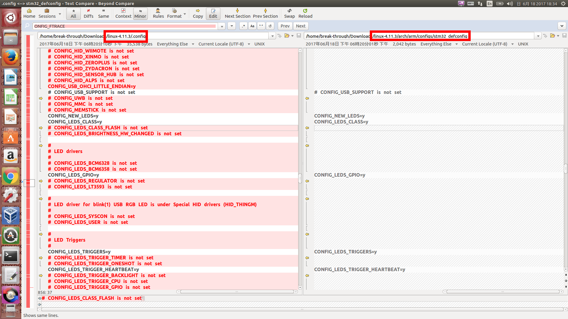
Explanation_2 Compiling kernel
make ARCH=arm CROSS_COMPILE=arm-none-eabi-
以上的命令,是使用 kernel folder 下的 ./.config 設定值去編譯 kernel 。
Device Tree Source Code
linux-4.11.3/arch/arm/boot/dts/stm32f429.dtsi
/* // Explanation_3
* Copyright 2015 - Maxime Coquelin <mcoquelin.stm32@gmail.com>
*
* This file is dual-licensed: you can use it either under the terms
* of the GPL or the X11 license, at your option. Note that this dual
* licensing only applies to this file, and not this project as a
* whole.
*
* a) This file is free software; you can redistribute it and/or
* modify it under the terms of the GNU General Public License as
* published by the Free Software Foundation; either version 2 of the
* License, or (at your option) any later version.
*
* This file is distributed in the hope that it will be useful,
* but WITHOUT ANY WARRANTY; without even the implied warranty of
* MERCHANTABILITY or FITNESS FOR A PARTICULAR PURPOSE. See the
* GNU General Public License for more details.
*
* You should have received a copy of the GNU General Public
* License along with this file; if not, write to the Free
* Software Foundation, Inc., 51 Franklin St, Fifth Floor, Boston,
* MA 02110-1301 USA
*
* Or, alternatively,
*
* b) Permission is hereby granted, free of charge, to any person
* obtaining a copy of this software and associated documentation
* files (the "Software"), to deal in the Software without
* restriction, including without limitation the rights to use,
* copy, modify, merge, publish, distribute, sublicense, and/or
* sell copies of the Software, and to permit persons to whom the
* Software is furnished to do so, subject to the following
* conditions:
*
* The above copyright notice and this permission notice shall be
* included in all copies or substantial portions of the Software.
*
* THE SOFTWARE IS PROVIDED "AS IS", WITHOUT WARRANTY OF ANY KIND,
* EXPRESS OR IMPLIED, INCLUDING BUT NOT LIMITED TO THE WARRANTIES
* OF MERCHANTABILITY, FITNESS FOR A PARTICULAR PURPOSE AND
* NONINFRINGEMENT. IN NO EVENT SHALL THE AUTHORS OR COPYRIGHT
* HOLDERS BE LIABLE FOR ANY CLAIM, DAMAGES OR OTHER LIABILITY,
* WHETHER IN AN ACTION OF CONTRACT, TORT OR OTHERWISE, ARISING
* FROM, OUT OF OR IN CONNECTION WITH THE SOFTWARE OR THE USE OR
* OTHER DEALINGS IN THE SOFTWARE.
*/
#include "skeleton.dtsi" // Explanation_3
#include "armv7-m.dtsi"
#include <dt-bindings/pinctrl/stm32f429-pinfunc.h>
#include <dt-bindings/clock/stm32fx-clock.h>
#include <dt-bindings/mfd/stm32f4-rcc.h>
/ { // Explanation_4
clocks { // Explanation_5
clk_hse: clk-hse { // Explanation_6
#clock-cells = <0>; // Explanation_7
compatible = "fixed-clock"; // Explanation_8
clock-frequency = <0>; // Explanation_8
};
clk-lse { // Explanation_9
#clock-cells = <0>;
compatible = "fixed-clock";
clock-frequency = <32768>;
};
clk-lsi {
#clock-cells = <0>;
compatible = "fixed-clock";
clock-frequency = <32000>;
};
clk_i2s_ckin: i2s-ckin {
#clock-cells = <0>;
compatible = "fixed-clock";
clock-frequency = <0>;
};
};
soc {
timer2: timer@40000000 { // Explanation_11
compatible = "st,stm32-timer";
reg = <0x40000000 0x400>; // Explanation_11
interrupts = <28>; // Explanation_12
clocks = <&rcc 0 STM32F4_APB1_CLOCK(TIM2)>;
status = "disabled"; // Explanation_13
};
timers2: timers@40000000 {
#address-cells = <1>; // Explanation_10
#size-cells = <0>; // Explanation_10
compatible = "st,stm32-timers";
reg = <0x40000000 0x400>;
clocks = <&rcc 0 STM32F4_APB1_CLOCK(TIM2)>; // Explanation_14
clock-names = "int"; // Explanation_15
status = "disabled";
pwm {
compatible = "st,stm32-pwm";
status = "disabled";
};
timer@1 {
compatible = "st,stm32-timer-trigger";
reg = <1>;
status = "disabled";
};
};
timer3: timer@40000400 {
compatible = "st,stm32-timer";
reg = <0x40000400 0x400>;
interrupts = <29>;
clocks = <&rcc 0 STM32F4_APB1_CLOCK(TIM3)>;
status = "disabled";
};
timers3: timers@40000400 {
#address-cells = <1>;
#size-cells = <0>;
compatible = "st,stm32-timers";
reg = <0x40000400 0x400>;
clocks = <&rcc 0 STM32F4_APB1_CLOCK(TIM3)>;
clock-names = "int";
status = "disabled";
pwm {
compatible = "st,stm32-pwm";
status = "disabled";
};
timer@2 {
compatible = "st,stm32-timer-trigger";
reg = <2>;
status = "disabled";
};
};
timer4: timer@40000800 {
compatible = "st,stm32-timer";
reg = <0x40000800 0x400>;
interrupts = <30>;
clocks = <&rcc 0 STM32F4_APB1_CLOCK(TIM4)>;
status = "disabled";
};
timers4: timers@40000800 {
#address-cells = <1>;
#size-cells = <0>;
compatible = "st,stm32-timers";
reg = <0x40000800 0x400>;
clocks = <&rcc 0 STM32F4_APB1_CLOCK(TIM4)>;
clock-names = "int";
status = "disabled";
pwm {
compatible = "st,stm32-pwm";
status = "disabled";
};
timer@3 {
compatible = "st,stm32-timer-trigger";
reg = <3>;
status = "disabled";
};
};
timer5: timer@40000c00 {
compatible = "st,stm32-timer";
reg = <0x40000c00 0x400>;
interrupts = <50>;
clocks = <&rcc 0 STM32F4_APB1_CLOCK(TIM5)>;
};
timers5: timers@40000c00 {
#address-cells = <1>;
#size-cells = <0>;
compatible = "st,stm32-timers";
reg = <0x40000C00 0x400>;
clocks = <&rcc 0 STM32F4_APB1_CLOCK(TIM5)>;
clock-names = "int";
status = "disabled";
pwm {
compatible = "st,stm32-pwm";
status = "disabled";
};
timer@4 {
compatible = "st,stm32-timer-trigger";
reg = <4>;
status = "disabled";
};
};
timer6: timer@40001000 {
compatible = "st,stm32-timer";
reg = <0x40001000 0x400>;
interrupts = <54>;
clocks = <&rcc 0 STM32F4_APB1_CLOCK(TIM6)>;
status = "disabled";
};
timers6: timers@40001000 {
#address-cells = <1>;
#size-cells = <0>;
compatible = "st,stm32-timers";
reg = <0x40001000 0x400>;
clocks = <&rcc 0 STM32F4_APB1_CLOCK(TIM6)>;
clock-names = "int";
status = "disabled";
timer@5 {
compatible = "st,stm32-timer-trigger";
reg = <5>;
status = "disabled";
};
};
timer7: timer@40001400 {
compatible = "st,stm32-timer";
reg = <0x40001400 0x400>;
interrupts = <55>;
clocks = <&rcc 0 STM32F4_APB1_CLOCK(TIM7)>;
status = "disabled";
};
timers7: timers@40001400 {
#address-cells = <1>;
#size-cells = <0>;
compatible = "st,stm32-timers";
reg = <0x40001400 0x400>;
clocks = <&rcc 0 STM32F4_APB1_CLOCK(TIM7)>;
clock-names = "int";
status = "disabled";
timer@6 {
compatible = "st,stm32-timer-trigger";
reg = <6>;
status = "disabled";
};
};
timers12: timers@40001800 {
#address-cells = <1>;
#size-cells = <0>;
compatible = "st,stm32-timers";
reg = <0x40001800 0x400>;
clocks = <&rcc 0 STM32F4_APB1_CLOCK(TIM12)>;
clock-names = "int";
status = "disabled";
pwm {
compatible = "st,stm32-pwm";
status = "disabled";
};
timer@11 {
compatible = "st,stm32-timer-trigger";
reg = <11>;
status = "disabled";
};
};
timers13: timers@40001c00 {
#address-cells = <1>;
#size-cells = <0>;
compatible = "st,stm32-timers";
reg = <0x40001C00 0x400>;
clocks = <&rcc 0 STM32F4_APB1_CLOCK(TIM13)>;
clock-names = "int";
status = "disabled";
pwm {
compatible = "st,stm32-pwm";
status = "disabled";
};
};
timers14: timers@40002000 {
#address-cells = <1>;
#size-cells = <0>;
compatible = "st,stm32-timers";
reg = <0x40002000 0x400>;
clocks = <&rcc 0 STM32F4_APB1_CLOCK(TIM14)>;
clock-names = "int";
status = "disabled";
pwm {
compatible = "st,stm32-pwm";
status = "disabled";
};
};
rtc: rtc@40002800 {
compatible = "st,stm32-rtc";
reg = <0x40002800 0x400>;
clocks = <&rcc 1 CLK_RTC>;
clock-names = "ck_rtc";
assigned-clocks = <&rcc 1 CLK_RTC>; // Explanation_16
assigned-clock-parents = <&rcc 1 CLK_LSE>; // Explanation_17
interrupt-parent = <&exti>;
interrupts = <17 1>; // Explanation_18
interrupt-names = "alarm"; // Explanation_19
st,syscfg = <&pwrcfg>; // Explanation_20
status = "disabled";
};
usart2: serial@40004400 {
compatible = "st,stm32-usart", "st,stm32-uart";
reg = <0x40004400 0x400>;
interrupts = <38>;
clocks = <&rcc 0 STM32F4_APB1_CLOCK(UART2)>;
status = "disabled";
};
usart3: serial@40004800 {
compatible = "st,stm32-usart", "st,stm32-uart";
reg = <0x40004800 0x400>;
interrupts = <39>;
clocks = <&rcc 0 STM32F4_APB1_CLOCK(UART3)>;
status = "disabled";
dmas = <&dma1 1 4 0x400 0x0>,
<&dma1 3 4 0x400 0x0>;
dma-names = "rx", "tx";
};
usart4: serial@40004c00 {
compatible = "st,stm32-uart";
reg = <0x40004c00 0x400>;
interrupts = <52>;
clocks = <&rcc 0 STM32F4_APB1_CLOCK(UART4)>;
status = "disabled";
};
usart5: serial@40005000 {
compatible = "st,stm32-uart";
reg = <0x40005000 0x400>;
interrupts = <53>;
clocks = <&rcc 0 STM32F4_APB1_CLOCK(UART5)>;
status = "disabled";
};
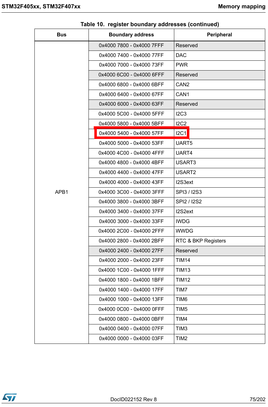
i2c1: i2c@40005400 {
compatible = "st,stm32f4-i2c";
reg = <0x40005400 0x400>;
interrupts = <31>,
<32>;
resets = <&rcc STM32F4_APB1_RESET(I2C1)>;
clocks = <&rcc 0 STM32F4_APB1_CLOCK(I2C1)>;
#address-cells = <1>;
#size-cells = <0>;
status = "disabled";
};
usart7: serial@40007800 {
compatible = "st,stm32-usart", "st,stm32-uart";
reg = <0x40007800 0x400>;
interrupts = <82>;
clocks = <&rcc 0 STM32F4_APB1_CLOCK(UART7)>;
status = "disabled";
};
usart8: serial@40007c00 {
compatible = "st,stm32-usart", "st,stm32-uart";
reg = <0x40007c00 0x400>;
interrupts = <83>;
clocks = <&rcc 0 STM32F4_APB1_CLOCK(UART8)>;
status = "disabled";
};
timers1: timers@40010000 {
#address-cells = <1>;
#size-cells = <0>;
compatible = "st,stm32-timers";
reg = <0x40010000 0x400>;
clocks = <&rcc 0 STM32F4_APB2_CLOCK(TIM1)>;
clock-names = "int";
status = "disabled";
pwm {
compatible = "st,stm32-pwm";
status = "disabled";
};
timer@0 {
compatible = "st,stm32-timer-trigger";
reg = <0>;
status = "disabled";
};
};
timers8: timers@40010400 {
#address-cells = <1>;
#size-cells = <0>;
compatible = "st,stm32-timers";
reg = <0x40010400 0x400>;
clocks = <&rcc 0 STM32F4_APB2_CLOCK(TIM8)>;
clock-names = "int";
status = "disabled";
pwm {
compatible = "st,stm32-pwm";
status = "disabled";
};
timer@7 {
compatible = "st,stm32-timer-trigger";
reg = <7>;
status = "disabled";
};
};
usart1: serial@40011000 {
compatible = "st,stm32-usart", "st,stm32-uart";
reg = <0x40011000 0x400>;
interrupts = <37>;
clocks = <&rcc 0 STM32F4_APB2_CLOCK(USART1)>;
status = "disabled";
dmas = <&dma2 2 4 0x400 0x0>,
<&dma2 7 4 0x400 0x0>;
dma-names = "rx", "tx";
};
usart6: serial@40011400 {
compatible = "st,stm32-usart", "st,stm32-uart";
reg = <0x40011400 0x400>;
interrupts = <71>;
clocks = <&rcc 0 STM32F4_APB2_CLOCK(USART6)>;
status = "disabled";
};
adc: adc@40012000 {
compatible = "st,stm32f4-adc-core";
reg = <0x40012000 0x400>;
interrupts = <18>;
clocks = <&rcc 0 STM32F4_APB2_CLOCK(ADC1)>;
clock-names = "adc";
interrupt-controller;
#interrupt-cells = <1>; // Explanation_27
#address-cells = <1>;
#size-cells = <0>;
status = "disabled";
adc1: adc@0 {
compatible = "st,stm32f4-adc";
#io-channel-cells = <1>;
reg = <0x0>;
clocks = <&rcc 0 STM32F4_APB2_CLOCK(ADC1)>;
interrupt-parent = <&adc>;
interrupts = <0>;
status = "disabled";
};
adc2: adc@100 {
compatible = "st,stm32f4-adc";
#io-channel-cells = <1>;
reg = <0x100>;
clocks = <&rcc 0 STM32F4_APB2_CLOCK(ADC2)>;
interrupt-parent = <&adc>;
interrupts = <1>;
status = "disabled";
};
adc3: adc@200 {
compatible = "st,stm32f4-adc";
#io-channel-cells = <1>;
reg = <0x200>;
clocks = <&rcc 0 STM32F4_APB2_CLOCK(ADC3)>;
interrupt-parent = <&adc>;
interrupts = <2>;
status = "disabled";
};
};
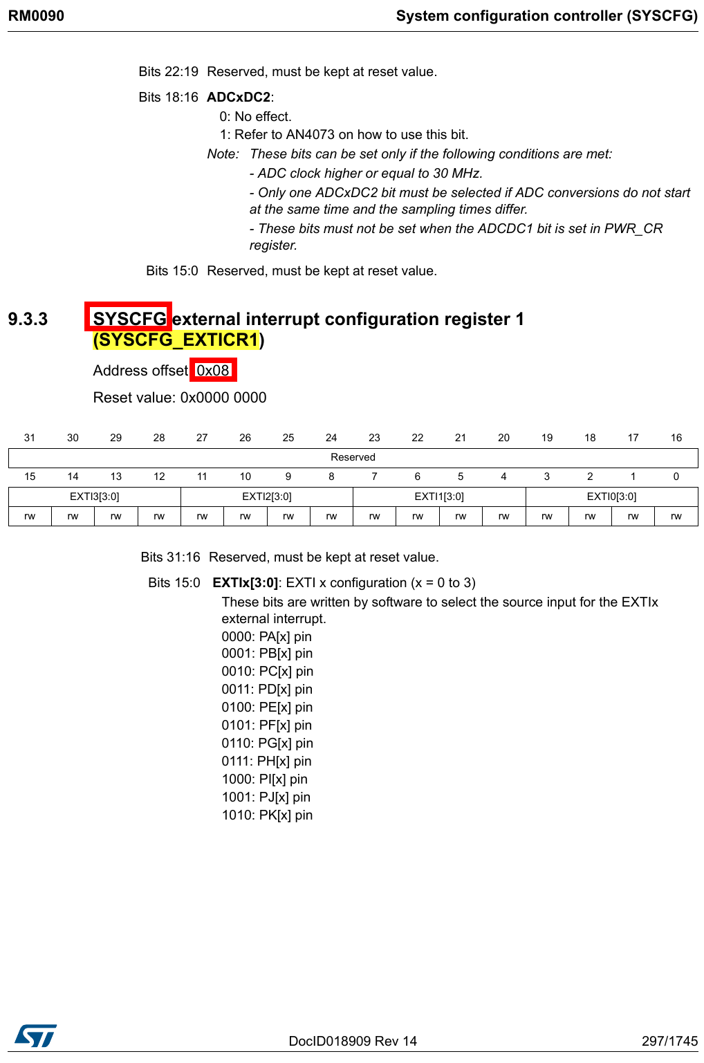
syscfg: system-config@40013800 {
compatible = "syscon";
reg = <0x40013800 0x400>;
};
exti: interrupt-controller@40013c00 {
compatible = "st,stm32-exti";
interrupt-controller;
#interrupt-cells = <2>;
reg = <0x40013C00 0x400>;
interrupts = <1>, <2>, <3>, <6>, <7>, <8>, <9>, <10>, <23>, <40>, <41>, <42>, <62>, <76>;
};
timers9: timers@40014000 {
#address-cells = <1>;
#size-cells = <0>;
compatible = "st,stm32-timers";
reg = <0x40014000 0x400>;
clocks = <&rcc 0 STM32F4_APB2_CLOCK(TIM9)>;
clock-names = "int";
status = "disabled";
pwm {
compatible = "st,stm32-pwm";
status = "disabled";
};
timer@8 {
compatible = "st,stm32-timer-trigger";
reg = <8>;
status = "disabled";
};
};
timers10: timers@40014400 {
#address-cells = <1>;
#size-cells = <0>;
compatible = "st,stm32-timers";
reg = <0x40014400 0x400>;
clocks = <&rcc 0 STM32F4_APB2_CLOCK(TIM10)>;
clock-names = "int";
status = "disabled";
pwm {
compatible = "st,stm32-pwm";
status = "disabled";
};
};
timers11: timers@40014800 {
#address-cells = <1>;
#size-cells = <0>;
compatible = "st,stm32-timers";
reg = <0x40014800 0x400>;
clocks = <&rcc 0 STM32F4_APB2_CLOCK(TIM11)>;
clock-names = "int";
status = "disabled";
pwm {
compatible = "st,stm32-pwm";
status = "disabled";
};
};
pwrcfg: power-config@40007000 {
compatible = "syscon";
reg = <0x40007000 0x400>;
};
pin-controller { // Explanation_32
#address-cells = <1>;
#size-cells = <1>;
compatible = "st,stm32f429-pinctrl";
ranges = <0 0x40020000 0x3000>;
interrupt-parent = <&exti>;
st,syscfg = <&syscfg 0x8>;
pins-are-numbered;
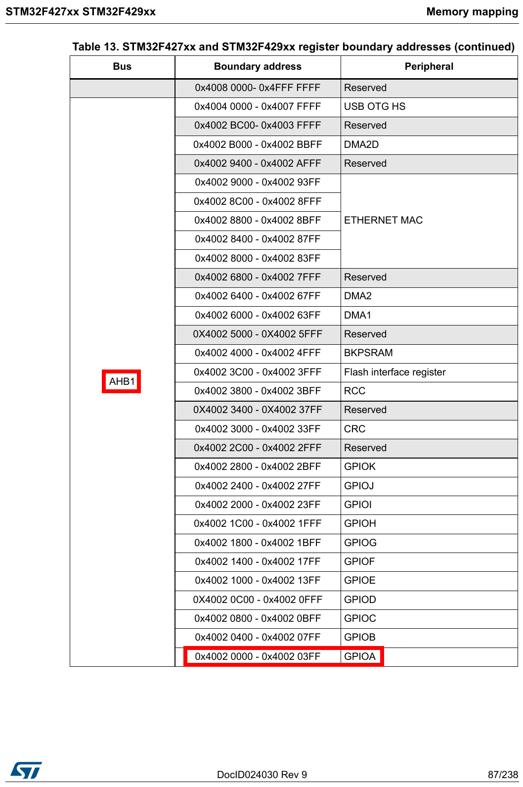
gpioa: gpio@40020000 {
gpio-controller;
#gpio-cells = <2>;
reg = <0x0 0x400>;
clocks = <&rcc 0 STM32F4_AHB1_CLOCK(GPIOA)>;
st,bank-name = "GPIOA";
};
gpiob: gpio@40020400 {
gpio-controller;
#gpio-cells = <2>;
reg = <0x400 0x400>;
clocks = <&rcc 0 STM32F4_AHB1_CLOCK(GPIOB)>;
st,bank-name = "GPIOB";
};
gpioc: gpio@40020800 {
gpio-controller;
#gpio-cells = <2>;
reg = <0x800 0x400>;
clocks = <&rcc 0 STM32F4_AHB1_CLOCK(GPIOC)>;
st,bank-name = "GPIOC";
};
gpiod: gpio@40020c00 {
gpio-controller;
#gpio-cells = <2>;
reg = <0xc00 0x400>;
clocks = <&rcc 0 STM32F4_AHB1_CLOCK(GPIOD)>;
st,bank-name = "GPIOD";
};
gpioe: gpio@40021000 {
gpio-controller;
#gpio-cells = <2>;
reg = <0x1000 0x400>;
clocks = <&rcc 0 STM32F4_AHB1_CLOCK(GPIOE)>;
st,bank-name = "GPIOE";
};
gpiof: gpio@40021400 {
gpio-controller;
#gpio-cells = <2>;
reg = <0x1400 0x400>;
clocks = <&rcc 0 STM32F4_AHB1_CLOCK(GPIOF)>;
st,bank-name = "GPIOF";
};
gpiog: gpio@40021800 {
gpio-controller;
#gpio-cells = <2>;
reg = <0x1800 0x400>;
clocks = <&rcc 0 STM32F4_AHB1_CLOCK(GPIOG)>;
st,bank-name = "GPIOG";
};
gpioh: gpio@40021c00 {
gpio-controller;
#gpio-cells = <2>;
reg = <0x1c00 0x400>;
clocks = <&rcc 0 STM32F4_AHB1_CLOCK(GPIOH)>;
st,bank-name = "GPIOH";
};
gpioi: gpio@40022000 {
gpio-controller;
#gpio-cells = <2>;
reg = <0x2000 0x400>;
clocks = <&rcc 0 STM32F4_AHB1_CLOCK(GPIOI)>;
st,bank-name = "GPIOI";
};
gpioj: gpio@40022400 {
gpio-controller;
#gpio-cells = <2>;
reg = <0x2400 0x400>;
clocks = <&rcc 0 STM32F4_AHB1_CLOCK(GPIOJ)>;
st,bank-name = "GPIOJ";
};
gpiok: gpio@40022800 {
gpio-controller;
#gpio-cells = <2>;
reg = <0x2800 0x400>;
clocks = <&rcc 0 STM32F4_AHB1_CLOCK(GPIOK)>;
st,bank-name = "GPIOK";
};
usart1_pins_a: usart1@0 {
pins1 {
pinmux = <STM32F429_PA9_FUNC_USART1_TX>;
bias-disable;
drive-push-pull;
slew-rate = <0>;
};
pins2 {
pinmux = <STM32F429_PA10_FUNC_USART1_RX>;
bias-disable;
};
};
usart3_pins_a: usart3@0 {
pins1 {
pinmux = <STM32F429_PB10_FUNC_USART3_TX>;
bias-disable;
drive-push-pull;
slew-rate = <0>;
};
pins2 {
pinmux = <STM32F429_PB11_FUNC_USART3_RX>;
bias-disable;
};
};
usbotg_hs_pins_a: usbotg_hs@0 {
pins {
pinmux = <STM32F429_PH4_FUNC_OTG_HS_ULPI_NXT>,
<STM32F429_PI11_FUNC_OTG_HS_ULPI_DIR>,
<STM32F429_PC0_FUNC_OTG_HS_ULPI_STP>,
<STM32F429_PA5_FUNC_OTG_HS_ULPI_CK>,
<STM32F429_PA3_FUNC_OTG_HS_ULPI_D0>,
<STM32F429_PB0_FUNC_OTG_HS_ULPI_D1>,
<STM32F429_PB1_FUNC_OTG_HS_ULPI_D2>,
<STM32F429_PB10_FUNC_OTG_HS_ULPI_D3>,
<STM32F429_PB11_FUNC_OTG_HS_ULPI_D4>,
<STM32F429_PB12_FUNC_OTG_HS_ULPI_D5>,
<STM32F429_PB13_FUNC_OTG_HS_ULPI_D6>,
<STM32F429_PB5_FUNC_OTG_HS_ULPI_D7>;
bias-disable;
drive-push-pull;
slew-rate = <2>;
};
};
ethernet_mii: mii@0 {
pins {
pinmux = <STM32F429_PG13_FUNC_ETH_MII_TXD0_ETH_RMII_TXD0>,
<STM32F429_PG14_FUNC_ETH_MII_TXD1_ETH_RMII_TXD1>,
<STM32F429_PC2_FUNC_ETH_MII_TXD2>,
<STM32F429_PB8_FUNC_ETH_MII_TXD3>,
<STM32F429_PC3_FUNC_ETH_MII_TX_CLK>,
<STM32F429_PG11_FUNC_ETH_MII_TX_EN_ETH_RMII_TX_EN>,
<STM32F429_PA2_FUNC_ETH_MDIO>,
<STM32F429_PC1_FUNC_ETH_MDC>,
<STM32F429_PA1_FUNC_ETH_MII_RX_CLK_ETH_RMII_REF_CLK>,
<STM32F429_PA7_FUNC_ETH_MII_RX_DV_ETH_RMII_CRS_DV>,
<STM32F429_PC4_FUNC_ETH_MII_RXD0_ETH_RMII_RXD0>,
<STM32F429_PC5_FUNC_ETH_MII_RXD1_ETH_RMII_RXD1>,
<STM32F429_PH6_FUNC_ETH_MII_RXD2>,
<STM32F429_PH7_FUNC_ETH_MII_RXD3>;
slew-rate = <2>;
};
};
adc3_in8_pin: adc@200 {
pins {
pinmux = <STM32F429_PF10_FUNC_ANALOG>;
};
};
pwm1_pins: pwm@1 {
pins {
pinmux = <STM32F429_PA8_FUNC_TIM1_CH1>,
<STM32F429_PB13_FUNC_TIM1_CH1N>,
<STM32F429_PB12_FUNC_TIM1_BKIN>;
};
};
pwm3_pins: pwm@3 {
pins {
pinmux = <STM32F429_PB4_FUNC_TIM3_CH1>,
<STM32F429_PB5_FUNC_TIM3_CH2>;
};
};
i2c1_pins: i2c1@0 {
pins {
pinmux = <STM32F429_PB9_FUNC_I2C1_SDA>,
<STM32F429_PB6_FUNC_I2C1_SCL>;
bias-disable;
drive-open-drain;
slew-rate = <3>;
};
};
};
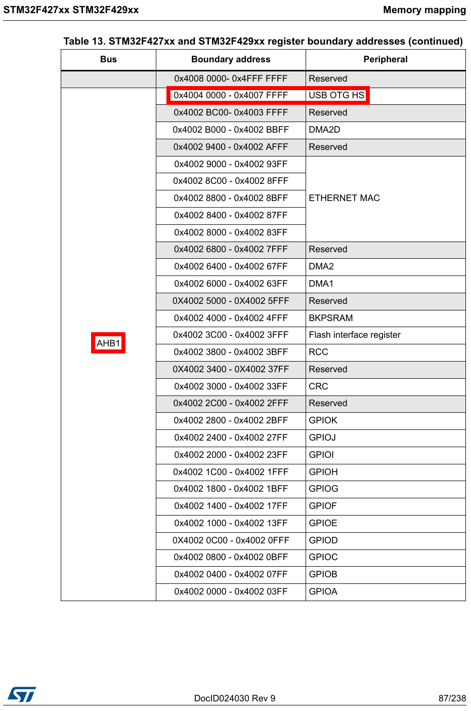
rcc: rcc@40023810 { // Explanation_29
#reset-cells = <1>;
#clock-cells = <2>; // Explanation_21
compatible = "st,stm32f42xx-rcc", "st,stm32-rcc";
reg = <0x40023800 0x400>;
clocks = <&clk_hse>, <&clk_i2s_ckin>; // Explanation_22
st,syscfg = <&pwrcfg>; // Explanation_23
assigned-clocks = <&rcc 1 CLK_HSE_RTC>; // Explanation_24
assigned-clock-rates = <1000000>; // Explanation_25
};
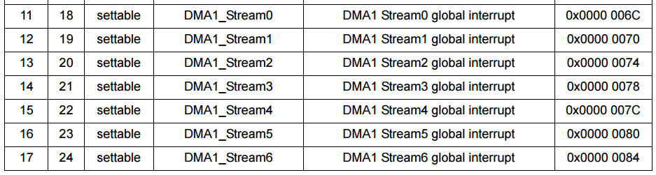
dma1: dma-controller@40026000 { // Explanation_28
compatible = "st,stm32-dma";
reg = <0x40026000 0x400>;
interrupts = <11>,
<12>,
<13>,
<14>,
<15>,
<16>,
<17>,
<47>;
clocks = <&rcc 0 STM32F4_AHB1_CLOCK(DMA1)>;
#dma-cells = <4>; //Explanation_26
};
dma2: dma-controller@40026400 { // Explanation_28
compatible = "st,stm32-dma";
reg = <0x40026400 0x400>;
interrupts = <56>,
<57>,
<58>,
<59>,
<60>,
<68>,
<69>,
<70>;
clocks = <&rcc 0 STM32F4_AHB1_CLOCK(DMA2)>;
#dma-cells = <4>;
st,mem2mem;
};
mac: ethernet@40028000 { // Explanation_30
compatible = "st,stm32-dwmac", "snps,dwmac-3.50a";
reg = <0x40028000 0x8000>;
reg-names = "stmmaceth";
interrupts = <61>;
interrupt-names = "macirq";
clock-names = "stmmaceth", "mac-clk-tx", "mac-clk-rx";
clocks = <&rcc 0 STM32F4_AHB1_CLOCK(ETHMAC)>,
<&rcc 0 STM32F4_AHB1_CLOCK(ETHMACTX)>,
<&rcc 0 STM32F4_AHB1_CLOCK(ETHMACRX)>;
st,syscon = <&syscfg 0x4>;
snps,pbl = <8>;
snps,mixed-burst;
status = "disabled";
};
usbotg_hs: usb@40040000 { // Explanation_31
compatible = "snps,dwc2";
reg = <0x40040000 0x40000>;
interrupts = <77>;
clocks = <&rcc 0 STM32F4_AHB1_CLOCK(OTGHS)>;
clock-names = "otg";
status = "disabled";
};
rng: rng@50060800 { // Explanation_31
compatible = "st,stm32-rng";
reg = <0x50060800 0x400>;
interrupts = <80>;
clocks = <&rcc 0 STM32F4_AHB2_CLOCK(RNG)>;
};
};
};
&systick {
clocks = <&rcc 1 SYSTICK>;
status = "okay";
};
linux-4.11.3/arch/arm/boot/dts/stm32f429-disco.dts
/*
 * Copyright 2015 - Maxime Coquelin <mcoquelin.stm32@gmail.com>
 *
 * This file is dual-licensed: you can use it either under the terms
 * of the GPL or the X11 license, at your option. Note that this dual
 * licensing only applies to this file, and not this project as a
 * whole.
 *
 *  a) This file is free software; you can redistribute it and/or
 *     modify it under the terms of the GNU General Public License as
 *     published by the Free Software Foundation; either version 2 of the
 *     License, or (at your option) any later version.
 *
 *     This file is distributed in the hope that it will be useful,
 *     but WITHOUT ANY WARRANTY; without even the implied warranty of
 *     MERCHANTABILITY or FITNESS FOR A PARTICULAR PURPOSE.  See the
 *     GNU General Public License for more details.
 *
 *     You should have received a copy of the GNU General Public
 *     License along with this file; if not, write to the Free
 *     Software Foundation, Inc., 51 Franklin St, Fifth Floor, Boston,
 *     MA 02110-1301 USA
 *
 * Or, alternatively,
 *
 *  b) Permission is hereby granted, free of charge, to any person
 *     obtaining a copy of this software and associated documentation
 *     files (the "Software"), to deal in the Software without
 *     restriction, including without limitation the rights to use,
 *     copy, modify, merge, publish, distribute, sublicense, and/or
 *     sell copies of the Software, and to permit persons to whom the
 *     Software is furnished to do so, subject to the following
 *     conditions:
 *
 *     The above copyright notice and this permission notice shall be
 *     included in all copies or substantial portions of the Software.
 *
 *     THE SOFTWARE IS PROVIDED "AS IS", WITHOUT WARRANTY OF ANY KIND,
 *     EXPRESS OR IMPLIED, INCLUDING BUT NOT LIMITED TO THE WARRANTIES
 *     OF MERCHANTABILITY, FITNESS FOR A PARTICULAR PURPOSE AND
 *     NONINFRINGEMENT. IN NO EVENT SHALL THE AUTHORS OR COPYRIGHT
 *     HOLDERS BE LIABLE FOR ANY CLAIM, DAMAGES OR OTHER LIABILITY,
 *     WHETHER IN AN ACTION OF CONTRACT, TORT OR OTHERWISE, ARISING
 *     FROM, OUT OF OR IN CONNECTION WITH THE SOFTWARE OR THE USE OR
 *     OTHER DEALINGS IN THE SOFTWARE.
 */

/dts-v1/;
#include "stm32f429.dtsi"
#include <dt-bindings/input/input.h>

/ {
	model = "STMicroelectronics STM32F429i-DISCO board";        // Explanation_8
	compatible = "st,stm32f429i-disco", "st,stm32f429";

	chosen {
		bootargs = "root=/dev/ram rdinit=/linuxrc";
		stdout-path = "serial0:115200n8";
	};

	memory {
		reg = <0x90000000 0x800000>;
	};

	aliases {
		serial0 = &usart1;
	};

	leds {
		compatible = "gpio-leds";
		red {
			gpios = <&gpiog 14 0>;
		};
		green {
			gpios = <&gpiog 13 0>;
			linux,default-trigger = "heartbeat";
		};
	};

	gpio_keys {
		compatible = "gpio-keys";
		#address-cells = <1>;
		#size-cells = <0>;
		autorepeat;
		button@0 {
			label = "User";
			linux,code = <KEY_HOME>;
			gpios = <&gpioa 0 0>;
		};
	};
};

&clk_hse {
	clock-frequency = <8000000>;
};

&rtc {
	assigned-clocks = <&rcc 1 CLK_RTC>;
	assigned-clock-parents = <&rcc 1 CLK_LSI>;
	status = "okay";
};

&usart1 {
	pinctrl-0 = <&usart1_pins_a>;        // Explanation_33
	pinctrl-names = "default";        // Explanation_33
	status = "okay";
};
Explanation_3
第一眼,映入眼簾的 code,不覺得很熟悉嗎?
有注解,有 include,像極了 C 語言,
請問 C 語言的注解、include 是那一個 software component 在處理呢?
是 Preprocessor,
-
comment
https://gcc.gnu.org/onlinedocs/cpp.pdf
1.2 Initial processing
Piece 3
4 All comments are replaced with single spaces. -
directive #include
https://gcc.gnu.org/onlinedocs/cpp.pdf
2 Header Files
Piece 7
You request the use of a header file in your program by including it, with the C preprocessing directive ‘#include’.
照這個 code 看起來應該也有 enable 類似C語言的 preprocessor,
linux-4.11.3/kernel/scripts/Makefile.lib
...
...
304 quiet_cmd_dtc = DTC     $@
305 cmd_dtc = mkdir -p $(dir ${dtc-tmp}) ;
306         $(CPP) $(dtc_cpp_flags) -x assembler-with-cpp -o $(dtc-tmp) $< ;
307         $(DTC) -O dtb -o $@ -b 0
308                 -i $(dir $<) $(DTC_FLAGS)
309                 -d $(depfile).dtc.tmp $(dtc-tmp) ;
310         cat $(depfile).pre.tmp $(depfile).dtc.tmp > $(depfile)
...
...
Line 306
-x
The -x option lets you override the default by specifying the language of the source file, rather than
inferring the language from the file suffix.
指定輸入檔案的語言,而不是使用預設的 language。
Reference
- ARM ® Compiler Version 6.00 Software Development Guide
http://infocenter.arm.com/help/topic/com.arm.doc.dui0773a/DUI0773A_software_development_guide.pdf
4.2 Preprocessing assembly code
piece 4-31 - Using the GNU Compiler Collection For gcc version 7.1.0 (GCC)
https://gcc.gnu.org/onlinedocs/gcc-7.1.0/gcc.pdf
3.2 Options Controlling the Kind of Output
piece 29
assembler-with-cpp
Assembly code that contains C directives, for example #include or #define, must be resolved by the C
preprocessor prior to assembling.
...
...
assembler-with-cpp indicates that the assembly code contains C directives and armclang must run the C preprocessor.
...
Reference
- ARM ® Compiler Version 6.00 Software Development Guide
http://infocenter.arm.com/help/topic/com.arm.doc.dui0773a/DUI0773A_software_development_guide.pdf
4.2 Preprocessing assembly code
piece 4-31 - Using the GNU Compiler Collection For gcc version 7.1.0 (GCC)
https://gcc.gnu.org/onlinedocs/gcc-7.1.0/gcc.pdf
3.2 Options Controlling the Kind of Output
piece 29
Explanation_4
每一個 device tree 都需要有一個 root node /
Reference
DevicetreeSpecification Release 0.1
https://www.devicetree.org/
Chapter three
All devicetrees shall have a root node
piece 21
Explanation_5
定義一個 device node 名為 clocks,
device node 裡面可以再定義一個 child device node。
Reference
DevicetreeSpecification Release 0.1
https://www.devicetree.org/
Chapter six
Node and property definitions
[label:] node-name[@unit-address] {
      [properties definitions]
      [child nodes]
}
piece 43
Explanation_6
定義一個 device node 名為 clk-hse,
及定義一個 label 名為 clk_hse,
在程式裡,可以使用 &label 存取這個 device node,
linux-4.11.3/arch/arm/boot/dts/stm32f429.dtsi
...
clk_hse: clk-hse {   // abbreviation High-Speed External user clock
...
             clock-frequency = <0>;
...
linux-4.11.3/arch/arm/boot/dts/stm32f429-disco.dts
&clk_hse {
        clock-frequency = <8000000>;
};
Reference
DevicetreeSpecification Release 0.1
https://www.devicetree.org/
Chapter six
Node and property definitions
[label:] node-name[@unit-address] {
      [properties definitions]
      [child nodes]
}
piece 43
Explanation_7
#clock-cells = <0>;
帶有 #clock-cells property 的 device node 是屬於 Clock providers,提供 clock 出去。
#clock-cells 是 Number of cells in a clock specifier,也就是 clock consumer 在使用 clock 時,需要幾個 u32 來表達出所要選擇的 clock source,
0 代表只有一個 clock output,也就是不需要 clock specifier。
1 代表有多個 clock output,需要一個 u32 來表示 clock specifier。
Ex1
Clock provider
clk_hse: clk-hse {
    #clock-cells = 0;
Clock consumer
// clock = <phandle, clock specifier>
clocks = <&clk_hse>;
Ex2
Clock provider
osc: oscillator {
    #clock-cells = <1>;
    clock-output-names = "ckil", "ckih";
};
Clock consumer
// clock = <phandle, clock specifier>
clocks = <&osc 1>;
Ex3
Clock provider
osc: oscillator {
    #clock-cells = <1>;
    clock-output-names = "ckiA", "ckiB","ckiC";
};
Clock consumer
// clock = <phandle, clock specifier>
clocks = <&osc 2>;
Reference
linux-4.11.3/Documentation/devicetree/bindings/clock/clock-bindings.txt
linux-4.11.3/Documentation/devicetree/bindings/clock/fixed-clock.txt
Explanation_8
談到 compatible property,
就要聯想到 model property,
這兩個 property 建議的 value 格式都是 "manufacturer,model",
那有什麼差別呢?
就看 code 的心得,
開發版製造商 製造開發板,
開發板使用很多的零件,
不是每個零件都是開發板製造商製造的,
如,mediatek 製造整個開發板,
但 charger ic 不是 mediatek 製造的。
model 大多用來描述 開發板的製造商 及 開發板的型號,
以我司的 UxxLxxx 為例,
model = "mediatek,UxxLxxx";
compatible 大多用來描述 零件的製造商 及 零件的型號,
以我司的 UxxLxxx project,charger ic 為例,
compatible = "ti,bq25896";
Reference
DevicetreeSpecification Release 0.1
https://www.devicetree.org/
2.2. Devicetree Structure and Conventions
piece 11
- compatible property
是用來傳遞字串 給 driver code,driver code 檢查字串,判斷 device tree 的 device node 是否屬於該 driver code 所需要驅動的 device。
Reference
DevicetreeSpecification Release 0.1
https://www.devicetree.org/
2.2. Devicetree Structure and Conventions
piece 11
- fixed-clock
表示這個 device 是 simple fixed-rate clock sources.
Reference
linux-4.11.3/Documentation/devicetree/bindings/clock/fixed-clock.txt
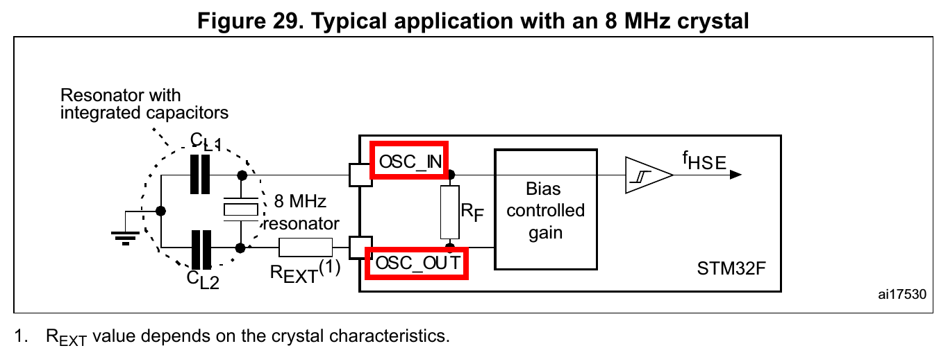
schematic 有一個 oscillator 8Mhz,
oscillator 是固定的 frequency 8Mhz output,符合 fixed-clock,

Reference
但 frequency 是 8Mhz,
為什麼 clock-frequency property 是 0 呢?
linux-4.11.3/arch/arm/boot/dts/stm32f429.dtsi
        clk_hse: clk-hse {
              ...
              clock-frequency = <0>;
              ...
        };
原因就在於 8Mhz 是在另一檔案設定的,
linux-4.11.3/arch/arm/boot/dts/stm32f429-disco.dts
&clk_hse {
        clock-frequency = <8000000>;
};
再來看硬體部分,
上面的線路圖,出現 SB18 SB19 SB20,
SB是什麼呢?
解釋一個名詞 solder bridge 錫橋,
兩個焊點間的細小架橋短路。
Reference
https://www.autodesk.com/products/eagle/blog/solder-bridging-pcb/
https://www.researchmfg.com/2011/02/soldering-defect-symptom/
現在要找尋 clock 被連到 那一隻 pin,
這是前面看過的 schematic,
裡面有三個 solder bridge,
Reference
這是 solder bridge 的狀態,
SB18、SB19、SB20 都是 off,

http://www.st.com/content/ccc/resource/technical/document/user_manual/6b/25/05/23/a9/45/4d/6a/DM00093903.pdf/files/DM00093903.pdf/jcr:content/translations/en.DM00093903.pdf
piece 19
所以 oscillaor X3 的 clock output pin PH0-OSC_IN 和 PH1-OSC_OUT 接到 主要 IC STM32F429ZIT6 的 PH0-OSC_IN 和 PH1-OSC_OUT。
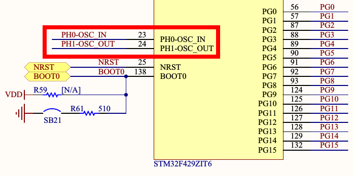
Reference
主要 IC STM32F429ZIT6 的 PH0-OSC_IN pin 和 PH1-OSC_OUT pin,各自對應到 pin position 23 及 24,又對應到 system 的 OSC_IN 及 OSC_OUT function,
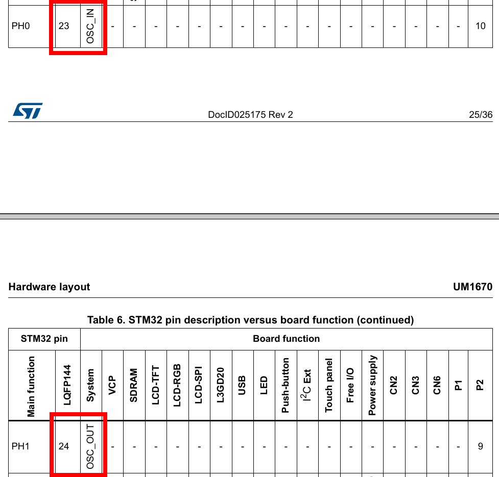
http://www.st.com/content/ccc/resource/technical/document/user_manual/6b/25/05/23/a9/45/4d/6a/DM00093903.pdf/files/DM00093903.pdf/jcr:content/translations/en.DM00093903.pdf
piece 25
看到以下的 schematic,
就可以確定前面所討論的 hse oscillator 相關 hardware wire 有連結到 chip 正確的 pin 。
http://www.st.com/content/ccc/resource/technical/document/datasheet/03/b4/b2/36/4c/72/49/29/DM00071990.pdf/files/DM00071990.pdf/jcr:content/translations/en.DM00071990.pdf
piece 120
Explanation_9
查尋 schematic,並沒有使用 frequency 為 32768 的 oscillator,
這有待研究,
也許 driver 有做什麼修改也不一定!

http://www.st.com/content/ccc/resource/technical/document/user_manual/6b/25/05/23/a9/45/4d/6a/DM00093903.pdf/files/DM00093903.pdf/jcr:content/translations/en.DM00093903.pdf
piece 32
Explanation_10
Example_1
/ {
        #address-cells = <0x1>;    // 在 root node 下使用 1 個 u32 來代表 address。
        #size-cells = <0x0>;       // 在 root node 下使用 0 個 u32 來代表 size,這不是一個很好的範例 使用 #size-cells = <0> 在 memory device,只是想讓各位了解 #size-cells = <0x0> 被使用的結果。
        ...
        ...
        memory {        // memory device
                ...
                reg = <0x90000000>;
                // 0x90000000 是存取 memory 的 address
                ...
	};
        ...
        ...
}
Example_2
/ {
        #address-cells = <0x1>;    // 在 root node 下使用 1 個 u32 來代表 address。
        #size-cells = <0x1>;       // 在 root node 下使用 1 個 u32 來代表 size。
        ...
        ...
        memory {        // memory device
                ...
                reg = <0x90000000 0x800000>;
                // 0x90000000 是存取 memory 的 address
                // 0x800000 是 memory 的 size。
                ...
        };
        ...
        ...
}
Example_3
/ {
        #address-cells = <0x2>;    // 在 root node 下使用 2 個 u32 來代表 address。
        #size-cells = <0x1>;       // 在 root node 下使用 1 個 u32 來代表 size。
        ...
        ...
        memory {        // memory device
                ...
                reg = <0x90000000 00000000 0x800000>;
                // 0x90000000 00000000 是存取 memory 的 address
                // 0x800000 是 memory 的 size。
                ...
	};
        ...
        ...
}
Example_4
/ {
        #address-cells = <0x2>;    // 在 root node 下使用 2 個 u32 來代表 address。
        #size-cells = <0x2>;       // 在 root node 下使用 2 個 u32 來代表 size。
        ...
        ...
        memory {        // memory device
                ...
                reg = <0x90000000 00000000 0x800000 00000000>;
                // 0x90000000 00000000 是存取 memory 的 address
                // 0x800000 00000000 是 memory 的 size。
                ...
        };
        ...
        ...
}
Reference
DevicetreeSpecification Release 0.1
https://www.devicetree.org/
2.3. Standard Properties
piece 12
Explanation_11
[label:] node-name[@unit-address] {
      [properties definitions]
      [child nodes]
}
40000000 (16進制)是 unit-address,存取 timer register 的 address,
0x400 是 timer register 的範圍。
Reference
DevicetreeSpecification Release 0.1
https://www.devicetree.org/
2.3. Standard Properties
piece 13
Explanation_12
28 (10 進制)是中斷號碼。
Reference
DevicetreeSpecification Release 0.1
https://www.devicetree.org/
2.4. Interrupts and Interrupt Mapping
piece 16
Explanation_13
這個 device 目前不能操作,但之後可以 enable,譬如需要 plug-in 的 device
Reference
DevicetreeSpecification Release 0.1
https://www.devicetree.org/
2.3. Standard Properties
piece 12
Explanation_14
第 0 個填 clock phandle,
第 1 個填 clock type,
value 0 代表 gated clocks,
value 1 代表 other clocks,
Reference
linux-4.11.3/Documentation/devicetree/bindings/clock/st,stm32-rcc.txt
Explanation_15
傳遞給 timers2 的 clock 命名為 int,在 driver 中可以使用。
Reference
linux-4.11.3/Documentation/devicetree/bindings/clock/clock-bindings.txt
Explanation_16
指定 準備要做修改的 clock source。
Reference
linux-4.11.3/Documentation/devicetree/bindings/rtc/st,stm32-rtc.txt
Explanation_17
重新指定 CLK_LSE 為 CLK_RTC 的 parent clock。
Reference
linux-4.11.3/Documentation/devicetree/bindings/rtc/st,stm32-rtc.txt
Explanation_18
發出 17 號中斷,1 有可能指定 active high 或是 active low。
Explanation_19
為 17 號中斷 命名為 alarm。
Explanation_20
phandle for pwrcfg, mandatory to disable/enable backup domain (RTC registers) write protection.
Explanation_21
各家 chip 使用方式不盡相同。
Reference
linux-4.11.3/Documentation/devicetree/bindings/clock/st,stm32-rcc.txt
Explanation_22
rcc device 使用了 clk_hse 及 clk_i2s_ckin 二個 clock。
Explanation_23
phandle for pwrcfg, platform power 相關的控制。
Explanation_24
指定要修改的 clock。
Explanation_25
將上述 clock 設定為 1000000 Hz。
Explanation_26
dma device node 規定要填 4 。
Explanation_27
Example1
    interrupt-controller@e000e100 {
        ...
        ...
        #interrupt-cells = <0x1>;    // 使用 1 個 u32 來表示 interrupt number。
        linux,phandle = <0x2>;
        phandle = <0x2>;
        ...
        ...
    };
Example2
    interrupt-controller@e000e100 {
        ...
        ...
        #interrupt-cells = <0x2>;    // 使用 2 個 u32 來表示 interrupt number。
        linux,phandle = <0x2 0>;
        phandle = <0x2 0>;
        ...
        ...
    };
Example3
    interrupt-controller@e000e100 {
        ...
        ...
        #interrupt-cells = <0x3>;    // 使用 3 個 u32 來表示 interrupt number。
        linux,phandle = <0x2 0 0>;
        phandle = <0x2 0 0>;
        ...
        ...
    };
Explanation_28
DMA address
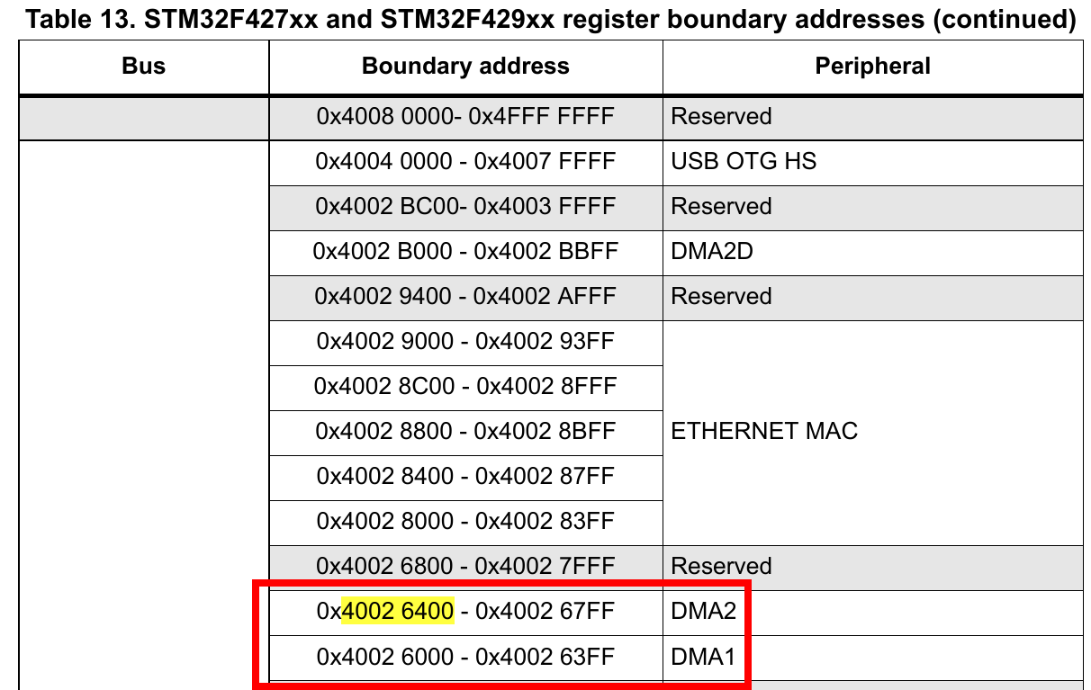

Reference
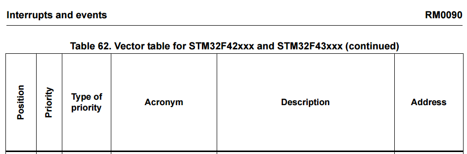
DMA interrupt number
STM32F429i 有二顆 DMA,
DMA interrupt number 要到 interrupts and event 章節去查詢,


Reference
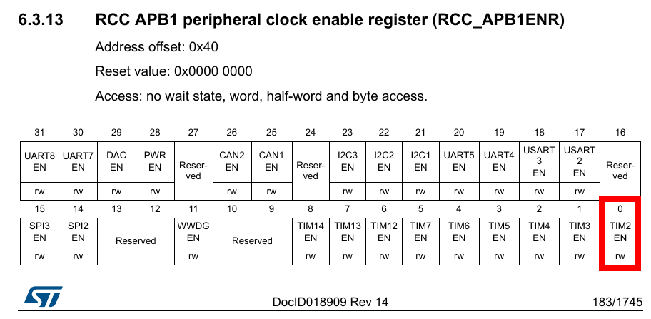
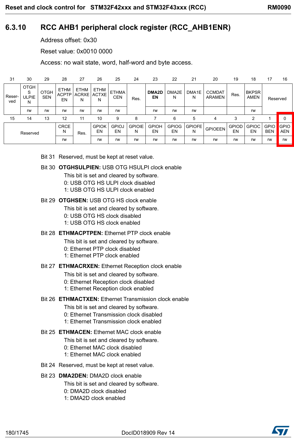
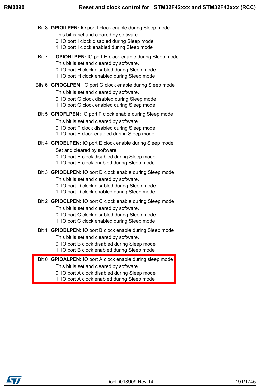
DMA gated clocks
Documentation/devicetree/bindings/clock/st,stm32-rcc.txt
...
...
 35 Specifying gated clocks
 36 =======================
 37
 38 The primary index must be set to 0.
 39
 40 The secondary index is the bit number within the RCC register bank, starting
 41 from the first RCC clock enable register (RCC_AHB1ENR, address offset 0x30).
...
...

Reference
dma-cells
Documentation/devicetree/bindings/dma/stm32-dma.txt
...
...

  1 * STMicroelectronics STM32 DMA controller
  2
  3 The STM32 DMA is a general-purpose direct memory access controller capable of
  4 supporting 8 independent DMA channels. Each channel can have up to 8 requests.
  5
  6 Required properties:
  7 - compatible: Should be "st,stm32-dma"
  8 - reg: Should contain DMA registers location and length. This should include
  9   all of the per-channel registers.
 10 - interrupts: Should contain all of the per-channel DMA interrupts in
 11   ascending order with respect to the DMA channel index.
 12 - clocks: Should contain the input clock of the DMA instance.
 13 - #dma-cells : Must be <4>. See DMA client paragraph for more details.
...
...
#dma-cells = <4>;
Reference
Documentation/devicetree/bindings/dma/stm32-dma.txt
st,mem2mem
Documentation/devicetree/bindings/dma/stm32-dma.txt
...
...
 15 Optional properties:
 16 - resets: Reference to a reset controller asserting the DMA controller
 17 - st,mem2mem: boolean; if defined, it indicates that the controller supports
 18   memory-to-memory transfer
...
...
st,mem2mem;
Reference
Documentation/devicetree/bindings/dma/stm32-dma.txt
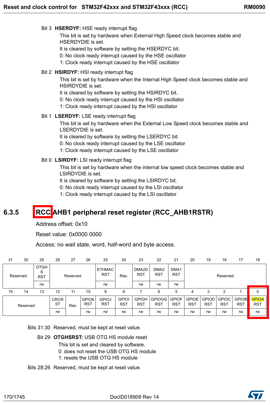
Explanation_29
unit-address
rcc: rcc@40023810 {

Reference
https://cdn.sparkfun.com/datasheets/Dev/dotNET/CD00225773.pdf
reset-cells
Ex
Reset Provider
...
...
        rcc: rcc@40023810 {
                #reset-cells = <1>;
...
...
Reset Consumer
...
...
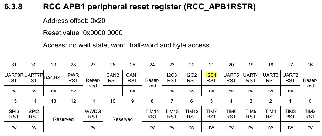
i2c1: i2c@40005400 {
resets = <&rcc STM32F4_APB1_RESET(I2C1)>;
...
...
kernel/Documentation/devicetree/bindings/reset/reset.txt
 35 #reset-cells:   Number of cells in a reset specifier; Typically 0 for nodes
 36                 with a single reset output and 1 for nodes with multiple
 37                 reset outputs.

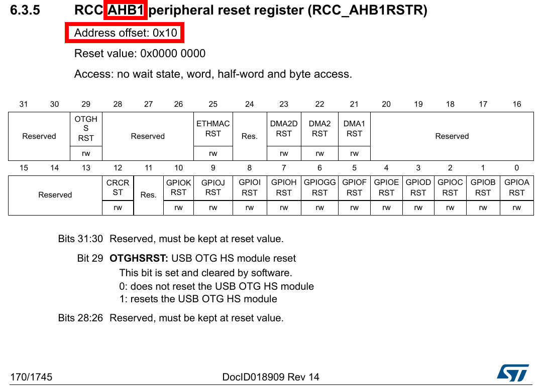
kernel/Document/devicetree/bindings/clock/st,stm32-rcc.txt
115 Specifying softreset control of devices
116 =======================================
117
118 Device nodes should specify the reset channel required in their "resets"
119 property, containing a phandle to the reset device node and an index specifying
120 which channel to use.
121 The index is the bit number within the RCC registers bank, starting from RCC
122 base address.
123 It is calculated as: index = register_offset / 4 * 32 + bit_offset.
124 Where bit_offset is the bit offset within the register.
125 For example, for CRC reset:
126   crc = AHB1RSTR_offset / 4 * 32 + CRCRST_bit_offset = 0x10 / 4 * 32 + 12 = 140
127
128 example:
129
130         timer2 {
131                 resets  = <&rcc STM32F4_APB1_RESET(TIM2)>;
132         };
Reference
kernel/Documentation/devicetree/bindings/reset/reset.txt
http://www.st.com/content/ccc/resource/technical/document/reference_manual/3d/6d/5a/66/b4/99/40/d4/DM00031020.pdf/files/DM00031020.pdf/jcr:content/translations/en.DM00031020.pdf
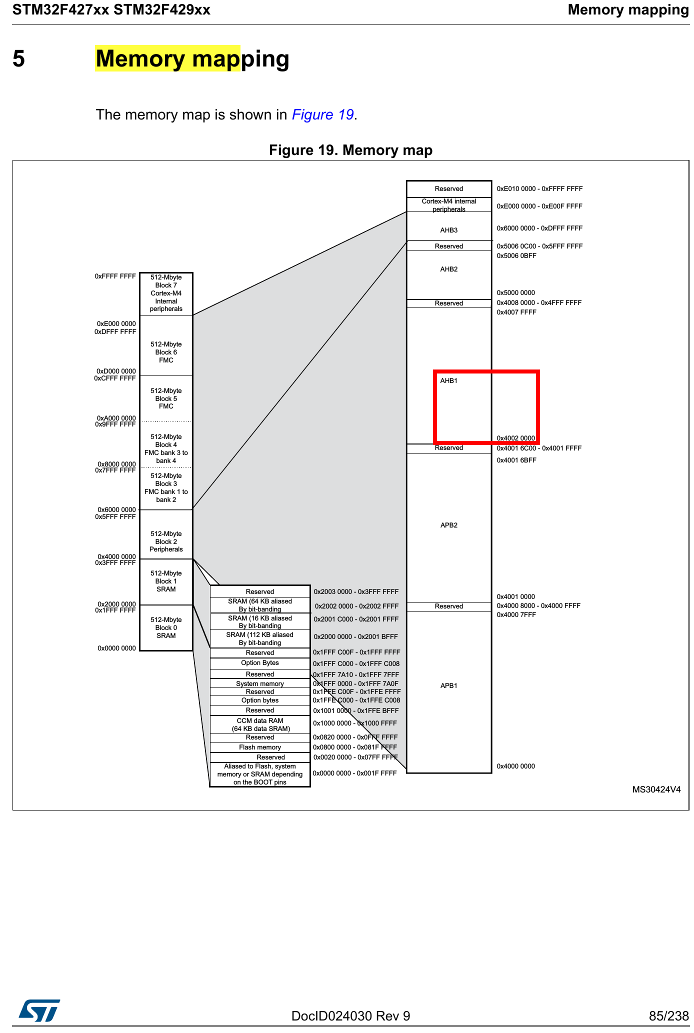
i2c1 unit address
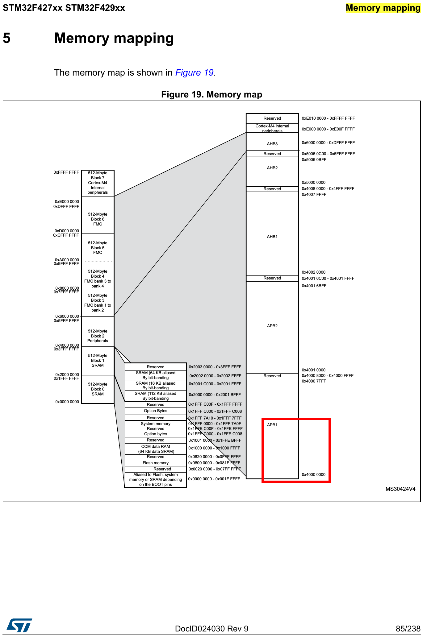
clock-cells
EX
Provider
        rcc: rcc@40023810 {
            #reset-cells = <1>;
            #clock-cells = <2>;    // 有二個 u32 當作 clock specifier。
            ...
Consumer
timer2: timer@40000000 {
            compatible = "st,stm32-timer";
            reg = <0x40000000 0x400>;
            interrupts = <28>;
            clocks = <&rcc 0 STM32F4_APB1_CLOCK(TIM2)>;    // 使用時需要1個 clock device phandle,2個 u32,1個 用來選擇 gated clocks 類別 或 other clocks 類別,1個用來指定那一個 clock 要被使用,也就是一個是指定 type,一個是指定 type 中的某個 clock。
            status = "disabled";
        };
kernel/Documentation/devicetree/bindings/clock/st,stm32-rcc.txt
Explanation_30
mac: ethernet@40028000 { // 看下方的圖。
compatible = "st,stm32-dwmac", "snps,dwmac-3.50a";
reg = <0x40028000 0x8000>; // 範圍大小可能有誤。
reg-names = "stmmaceth"; // names of the registers.
interrupts = <61>;
interrupt-names = "macirq";
clock-names = "stmmaceth", "mac-clk-tx", "mac-clk-rx";
clocks = <&rcc 0 STM32F4_AHB1_CLOCK(ETHMAC)>,
<&rcc 0 STM32F4_AHB1_CLOCK(ETHMACTX)>,
<&rcc 0 STM32F4_AHB1_CLOCK(ETHMACRX)>;
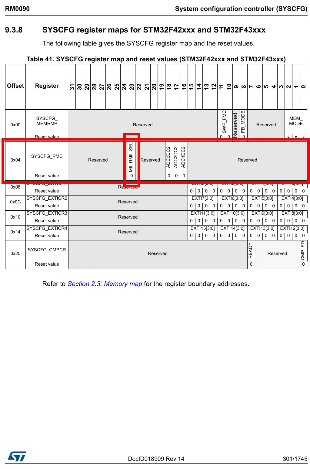
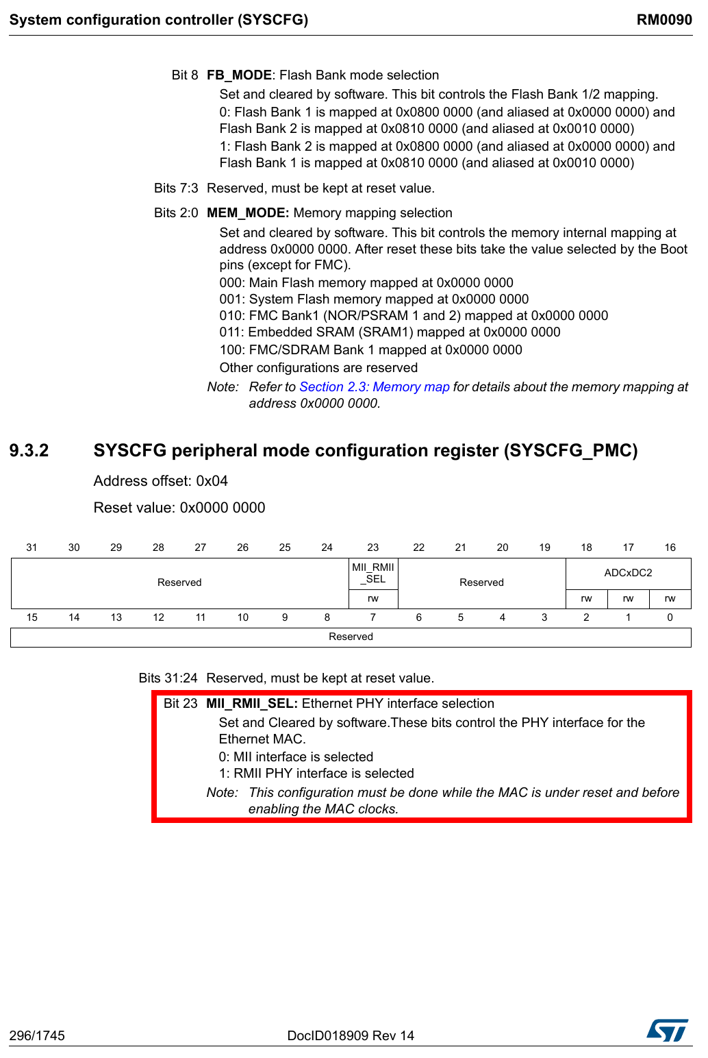
st,syscon = <&syscfg 0x4>; // system configuration controller,關於 remap,mac phy interface 選擇。
snps,pbl = <8>;
snps,mixed-burst;
status = "disabled";
};


http://www.st.com/content/ccc/resource/technical/document/datasheet/03/b4/b2/36/4c/72/49/29/DM00071990.pdf/files/DM00071990.pdf/jcr:content/translations/en.DM00071990.pdf
devicetree/bindings/media/st,st-hva.txt
snps,pbl
Programmable Burst Length (tx and rx)
kernel/Documentation/devicetree/bindings/net/stmmac.txt
snps,mixed-burst Program the DMA to use the mixed burst mode
kernel/Documentation/devicetree/bindings/net/stmmac.txt
Explanation_31
Random number generator (RNG)
        rng: rng@50060800 {
            compatible = "st,stm32-rng";
            reg = <0x50060800 0x400>;
            interrupts = <80>;
            clocks = <&rcc 0 STM32F4_AHB2_CLOCK(RNG)>;

        };
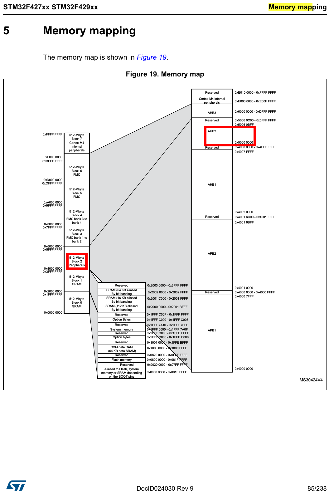
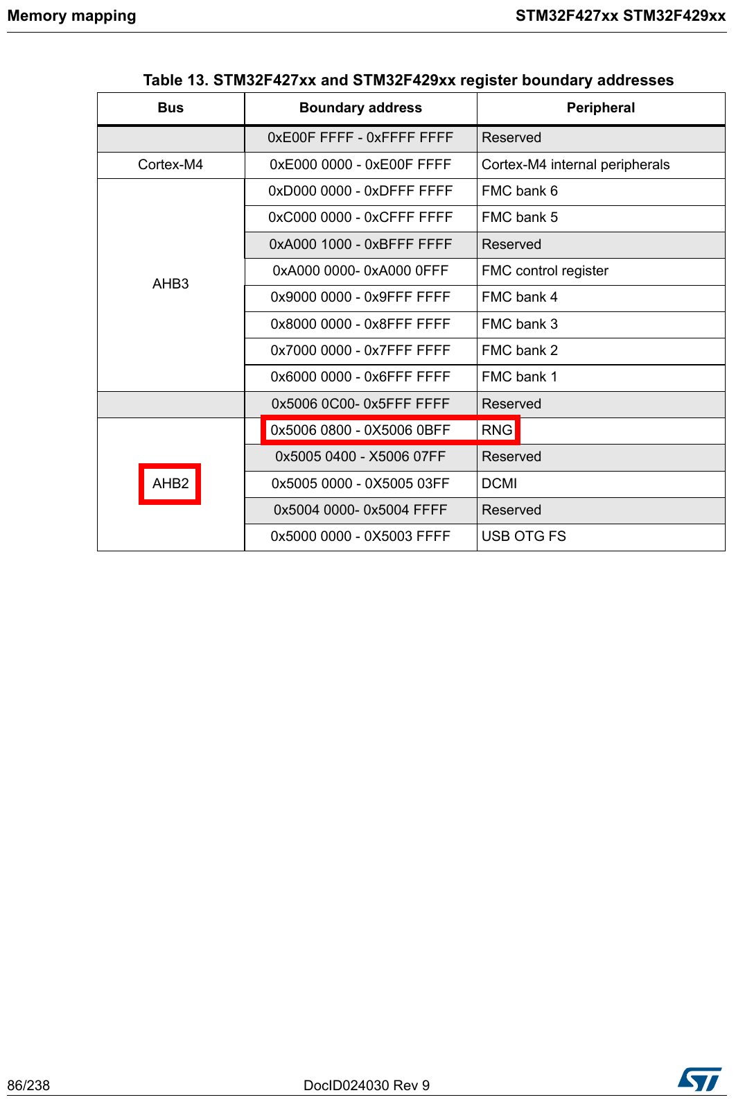

...
#define STM32F4_AHB2_CLOCK(bit)	(STM32F4_RCC_AHB2_##bit + 0x20)
#define STM32F4_RCC_AHB2_RNG	6
...
kernel/include/dt-bindings/mfd/stm32f4-rcc.h
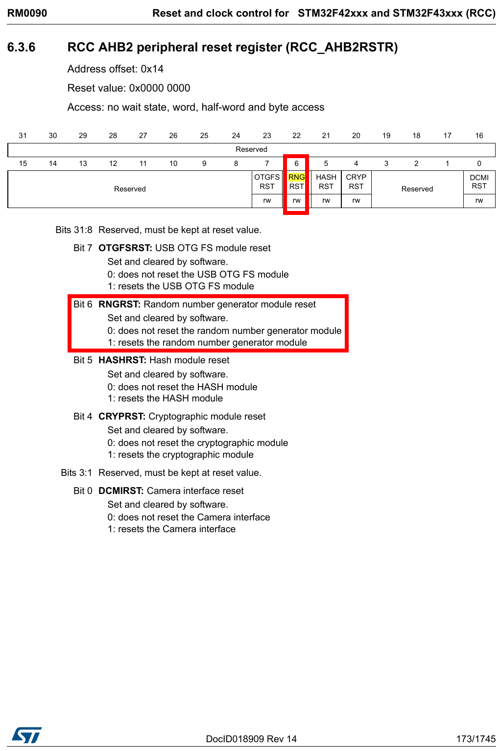
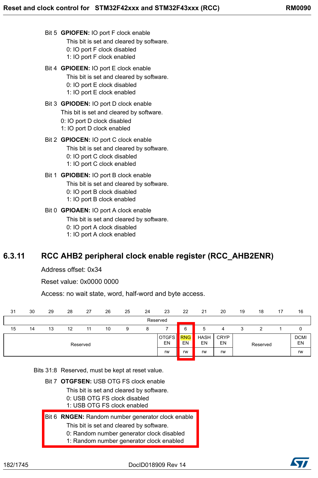

http://www.st.com/content/ccc/resource/technical/document/reference_manual/3d/6d/5a/66/b4/99/40/d4/DM00031020.pdf/files/DM00031020.pdf/jcr:content/translations/en.DM00031020.pdf
Explanation_31
        usbotg_hs: usb@40040000 {
            compatible = "snps,dwc2";
            reg = <0x40040000 0x40000>;
            interrupts = <77>;
            clocks = <&rcc 0 STM32F4_AHB1_CLOCK(OTGHS)>;
            clock-names = "otg";
            status = "disabled";
        };

Explanation_32
        pin-controller {
            #address-cells = <1>;
            #size-cells = <1>;
            compatible = "st,stm32f429-pinctrl";
            ranges = <0 0x40020000 0x3000>;
            interrupt-parent = <&exti>;
            st,syscfg = <&syscfg 0x8>;
            pins-are-numbered;

            gpioa: gpio@40020000 {
                gpio-controller;    // Indicates this device is a GPIO controller.    from kernel/Documentation/devicetree/bindings/pinctrl/st,stm32-pinctrl.txt
                #gpio-cells = <2>;
                reg = <0x0 0x400>;
                clocks = <&rcc 0 STM32F4_AHB1_CLOCK(GPIOA)>;
                st,bank-name = "GPIOA";
            };
ranges
Translating between parent address space and child address space.
value type : (child-bus-address, parent-bus-address, length)
Devicetree Specification Release 0.1
interrupt-parent
指定中斷父親
Devicetree Specification Release 0.1
st,syscfg
Should be phandle/offset pair. The phandle to the syscon node which includes IRQ mux selection register, and the offset of the IRQ mux selection register.
kernel/Documentation/devicetree/bindings/pinctrl/st,stm32-pinctrl.txt
http://www.st.com/content/ccc/resource/technical/document/reference_manual/3d/6d/5a/66/b4/99/40/d4/DM00031020.pdf/files/DM00031020.pdf/jcr:content/translations/en.DM00031020.pdf
pins-are-numbered
Specify the subnodes are using numbered pinmux to specify pins.
I don't know yet.
unit-address

gpio-cells
 24  - #gpio-cells    : Should be two.
 25                         The first cell is the pin number
 26                         The second one is the polarity:
 27                                 - 0 for active high
 28                                 - 1 for active low
gpio-cells 是 gpio provider 使用的。
kernel/Documentation/devicetree/bindings/pinctrl/st,stm32-pinctrl.txt
single-gpio ::= <gpio-phandle> <gpio-specifier>
gpio-specifier 需由二個 cell 組成。參考上。
linux-4.11.3/Documentation/devicetree/bindings/gpio/gpio.txt
gpios = <&gpiog 14 0>;
gpios 是 gpio consumer 使用的。
Specify GPIO
kernel/Documentation/devicetree/bindings/gpio/gpio.txt
reg
reg = <0x0 0x400>;
gpio 是一個子節點,
從 ranges 可以得知,child space address 是由 0 開始,
而範圍從以下可得知是 0x400,

http://www.st.com/content/ccc/resource/technical/document/datasheet/03/b4/b2/36/4c/72/49/29/DM00071990.pdf/files/DM00071990.pdf/jcr:content/translations/en.DM00071990.pdf
clocks
clocks = <&rcc 0 STM32F4_AHB1_CLOCK(GPIOA)>;
#define STM32F4_AHB1_CLOCK(bit) (STM32F4_RCC_AHB1_##bit)
#define STM32F4_RCC_AHB1_GPIOA	0
kernl/include/dt-bindings/mfd/stm32f4-rcc.h


http://www.st.com/content/ccc/resource/technical/document/reference_manual/3d/6d/5a/66/b4/99/40/d4/DM00031020.pdf/files/DM00031020.pdf/jcr:content/translations/en.DM00031020.pdf
Explanation_33
&usart1 {
    pinctrl-0 = <&usart1_pins_a>;
    pinctrl-names = "default";
    status = "okay";
};
65 pinctrl-1:      List of phandles, each pointing at a pin configuration
66                     node within a pin controller.
67 ...
68 pinctrl-n:      List of phandles, each pointing at a pin configuration
69                 node within a pin controller.
70 pinctrl-names:  The list of names to assign states.
Example
&example {
    pinctrl-names = "state_0", "state_1", "state_2";
    pinctrl-0 = <&example_pins_state_0>;
    pinctrl-1 = <&example_pins_state_1>;
    pinctrl-2 = <&example_pins_state_2>;
    status = "okay";
};
Reference
linux-4.11.3/Documentation/devicetree/bindings/pinctrl/pinctrl-bindings.txt
心得
若想知道 property 的真正用法,
還是得回到 driver code 的來看使用方式,
因為 property 的 value 最後還是得傳到 driver code。