通讯协议可以理解为约束多设备通讯的一套规则,像Modbus,TCP/IP, BLE都是在生产生活常用的协议。不过协议落实到实际应用后,就可以理解为对数据的结构化处理,我之前写的串口点亮LED的实现就涉及了简单的协议制定,对于嵌入式Linux来说,那一套协议当然也可以实践,但是那套协议有个重要的缺陷,协议内部从起始端的数据接收,一直到发送端的数据接收,都是和硬件强耦合的,这就造成如果我们由多种途径修改内部数据,协议很难被复用,另外每一次最后的执行都是直接操作硬件,当然只有串口控制时没有问题,但当有多个渠道(如网络,CAN,BLE等模块)同时操作硬件时,涉及硬件的同步问题繁琐且很难约束,因此本节就改进之前的协议,进行代码的实现。
参考资料
1.嵌入式学习笔记(综合提高篇 第一章) -- 利用串口点亮/关闭LED灯
2.《C++ Primer Plus》
协议制定
协议的制定在大致的数据发送和返回数据结构上可以与原有的协议大致一致。
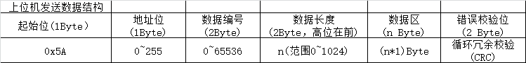
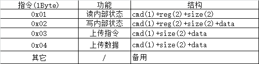
上位机发送指令包含起始位,地址位(用于多机通讯),数据长度(指示内部后面的数据长度),实际数据,CRC校验位这些基础结构,不过增加了数据编号位,它是2字节的随机数,在处理完成后可以用于上位机验证返回的数据是否正常,不过对比可以发现,原先协议里面的指令不在上位机数据结构,这个后面会提到。
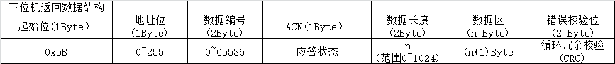
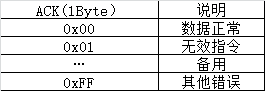
下位机返回指令也是起始位,地址位,ACK应答状态,数据长度,数据区和CRC校验位,同时包含编号用于上位机的校验,
上位机发送数据结构:
下位机返回数据结构:
确认了通讯的结构后,下位机代码就可以实现了,其中接收数据代码如下:


 1 int protocol_info::check_receive_data(int fd)
 2 {
 3     int nread;
 4     int CrcRecv, CrcCacl;
 5     struct req_frame *frame_ptr;
 6
 7     /*从设备中读取数据*/
 8     nread = this->device_read(fd, &this->rx_ptr[this->rx_size],
 9                              (this->max_buf_size-this->rx_size));
10     if(nread > 0)
11     {
12        this->rx_size += nread;
13        frame_ptr = (struct req_frame *)this->rx_ptr;
14
15        /*接收到头不符合预期*/
16        if(frame_ptr->head != PROTOCOL_REQ_HEAD) {
17             USR_DEBUG("No Valid Head
");
18             this->rx_size = 0;
19             return RT_FAIL;
20        }
21
22        /*已经接收到长度数据*/
23        else if(this->rx_size > 5){
24             int nLen;
25
26             /*设备ID检测*/
27             if(frame_ptr->id != PROTOCOL_DEVICE_ID)
28             {
29                 this->rx_size = 0;
30                 USR_DEBUG("Valid ID
");
31                 return RT_FAIL;
32             }
33
34             /*获取接收数据的总长度*/
35             this->rx_data_size = LENGTH_CONVERT(frame_ptr->length);
36
37             /*crc冗余校验*/
38             nLen = this->rx_data_size+FRAME_HEAD_SIZE+CRC_SIZE;
39             if(this->rx_size >= nLen)
40             {
41                 /*计算head后到CRC尾之前的所有数据的CRC值*/
42                 CrcRecv = (this->rx_ptr[nLen-2]<<8) + this->rx_ptr[nLen-1];
43                 CrcCacl = this->crc_calculate(&this->rx_ptr[1], nLen-CRC_SIZE-1);
44                 if(CrcRecv == CrcCacl){
45                     this->packet_id = LENGTH_CONVERT(frame_ptr->packet_id);
46                     return RT_OK;
47                 }
48                 else{
49                     this->rx_size = 0;
50                     USR_DEBUG("CRC Check ERROR!. rx_data:%d, r:%d, c:%d
", this->rx_data_size, CrcRecv, CrcCacl);
51                     return RT_FAIL;
52                 }
53             }
54        }
55     }
56     return RT_EMPTY;
57 }
因为是嵌入式Linux开发,因此推荐使用C++, 封装可以让代码结构更加清晰,从代码的实现可以看到实现包含:硬件的数据接收,起始位检测,数据编号的获取,以及后续数据的接收和数据的CRC校验,至于发送数据,则主要是创建发送数据的接口,代码如下:
 1 /**
 2  * 生成发送的数据包格式
 3  *
 4  * @param ack 应答数据的状态
 5  * @param size 应答有效数据的长度
 6  * @param pdata 应答有效数据的首指针
 7  *
 8  * @return 执行执行的结果
 9  */
10 int protocol_info::create_send_buf(uint8_t ack, uint16_t size, uint8_t *pdata)
11 {
12     uint8_t out_size, index;
13     uint16_t crc_calc;
14
15     out_size = 0;
16     this->tx_ptr[out_size++] = PROTOCOL_ACK_HEAD;
17     this->tx_ptr[out_size++] = PROTOCOL_DEVICE_ID;
18     this->tx_ptr[out_size++] = (uint8_t)(this->packet_id>>8);
19     this->tx_ptr[out_size++] = (uint8_t)(this->packet_id&0xff);
20     this->tx_ptr[out_size++] = ack;
21     this->tx_ptr[out_size++] = (uint8_t)(size>>8);
22     this->tx_ptr[out_size++] = (uint8_t)(size&0xff);
23
24     if(size != 0 && pdata != NULL)
25     {
26         for(index=0; index<size; index++)
27         {
28             this->tx_ptr[out_size++] = *(pdata+index);
29         }
30     }
31
32     crc_calc = this->crc_calculate(&this->tx_ptr[1], out_size-1);
33     this->tx_ptr[out_size++] = (uint8_t)(crc_calc>>8);
34     this->tx_ptr[out_size++] = (uint8_t)(crc_calc&0xff);
35
36     return out_size;
37 }
这部分即为通讯相关的结构数据实现,通关协议的发送和接收结构的剥离,此时我们已经能够处理实际的数据,下面也是主要改进内容。
数据的处理
在之前的协议设计中,指令是包含在上述数据结构中的,到具体执行的地方直接操作硬件,对于串口操作LED,流程如下:
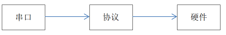
在整个流程中,协议和串口,以及硬件绑定,这在多任务处理时,对于硬件的同步处理就比较困难,而且硬件的处理也是十分耗时的,特别是对于很多时候也影响通讯的效率,记得在操作系统的学习中,有特别经典的一句话,解耦的通常方法就是增加中间层,在本项目也是如此,在协议和硬件中增加缓冲数据层,这样同步问题都在缓冲数据层处理,就避免了对硬件的资源抢占动作,修改后结构如下:
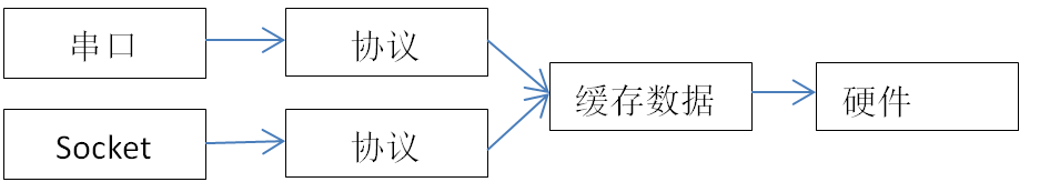
为了实现这个结构,就增加对于缓存数据的处理,其中缓存数据的处理结构如下:
 1 class app_reg
 2 {
 3 public:
 4     app_reg(void);
 5         ~app_reg();
 6     int hardware_refresh(void); /*硬件的实际更新*/
 7     uint16_t get_multiple_val(uint16_t reg_index, uint16_t size, uint8_t *pstart); /*获取寄存器的值*/
 8     void set_multiple_val(uint16_t reg_index, uint16_t size, uint8_t *pstart);  /*设置寄存器的值*/
 9     int diff_modify_reg(uint16_t reg_index, uint16_t size, uint8_t *pstart, uint8_t *psrc);
10 private:
11     uint8_t reg[REG_NUM];
12     pthread_mutex_t reg_mutex; /*数据读取都要执行该锁*/
13 };
其中hardware_refresh就是实际对硬件的操作,其它协议通关get和set即可修改缓存数据,在协议中操作修改内部缓存数据就可以了,剩余硬件相关处理就由缓存数据管理,其中协议中的执行如下:
 1 /**
 2  * 执行具体的指令, 并提交数据到上位机
 3  *
 4  * @param fd 执行的设备ID号
 5  *
 6  * @return 执行执行的结果
 7  */
 8 int protocol_info::execute_command(int fd)
 9 {
10     uint8_t cmd;
11     uint16_t reg_index, size;
12     uint8_t *cache_ptr;
13     app_reg  *app_reg_ptr;
14
15     cmd = this->rx_data_ptr[0];
16     reg_index = this->rx_data_ptr[1]<<8 | this->rx_data_ptr[2];
17     size = this->rx_data_ptr[3]<<8 | this->rx_data_ptr[4];
18     cache_ptr = (uint8_t *)malloc(this->max_buf_size);
19     this->tx_size = 0;
20     app_reg_ptr = get_app_reg();
21
22     switch (cmd)
23     {
24         case CMD_REG_READ:
25             app_reg_ptr->get_multiple_val(reg_index, size, cache_ptr);
26             this->tx_size = this->create_send_buf(ACK_OK, size, cache_ptr);
27             break;
28         case CMD_REG_WRITE:
29             memcpy(cache_ptr, &this->rx_data_ptr[5], size);
30             app_reg_ptr->set_multiple_val(reg_index, size, cache_ptr);
31             this->tx_size = this->create_send_buf(ACK_OK, 0, NULL);
32             break;
33         case CMD_UPLOAD_CMD:
34             break;
35         case CMD_UPLOAD_DATA:
36             break;
37         default:
38             break;
39     }
40     free(cache_ptr);
41
42     /*发送数据,并清空接收数据*/
43     this->rx_size = 0;
44     this->device_write(fd, this->tx_ptr, this->tx_size);
45     return RT_OK;
46 }
对于硬件的处理则由数据层管理,结构如下:
 1 /**
 2  * 根据寄存器更新内部硬件参数
 3  *
 4  * @param NULL
 5  *
 6  * @return NULL
 7  */
 8 int app_reg::hardware_refresh(void)
 9 {
10     uint8_t *reg_ptr;
11     uint8_t *reg_cache_ptr;
12     uint8_t is_reg_modify;
13     uint16_t reg_set_status;
14
15     reg_ptr = (uint8_t *)malloc(REG_CONFIG_NUM);
16     reg_cache_ptr = (uint8_t *)malloc(REG_CONFIG_NUM);
17     is_reg_modify = 0;
18
19     if(reg_ptr != NULL && reg_cache_ptr != NULL)
20     {
21         /*读取所有的寄存值并复制到缓存中*/
22         this->get_multiple_val(0, REG_CONFIG_NUM, reg_ptr);
23         memcpy(reg_cache_ptr, reg_ptr, REG_CONFIG_NUM);
24
25         /*有设置消息*/
26         reg_set_status = reg_ptr[1] <<8 | reg_ptr[0];
27         if(reg_set_status&0x01)
28         {
29             /*LED设置处理*/
30             if(reg_set_status&(1<<1))
31             {
32                 led_convert(reg_ptr[2]&0x01);
33             }
34
35             /*修改beep*/
36             if(reg_set_status&(1<<2))
37             {
38                 beep_convert((reg_ptr[2]>>1)&0x01);
39             }
40
41             reg_ptr[0] = 0;
42             reg_ptr[1] = 0;
43             is_reg_modify = 1;
44         }
45
46         /*更新寄存器状态*/
47         if(is_reg_modify == 1){
48             if(this->diff_modify_reg(0, REG_CONFIG_NUM, reg_ptr, reg_cache_ptr) == RT_OK){
49                 is_reg_modify = 0;
50             }
51             else
52             {
53                 free(reg_ptr);
54                 free(reg_cache_ptr);
55                 USR_DEBUG("modify by other interface
");
56                 return RT_FAIL;
57             }
58         }
59
60         free(reg_ptr);
61         free(reg_cache_ptr);
62     }
63     else{
64         USR_DEBUG("malloc error
");
65     }
66
67     return RT_OK;
68 }
这里就将对硬件的处理,就准换成了对内部缓存数据的处理,缓存数据由专用的线程管理,执行对硬件的操作。
定义发送的实际指令如下
返回应答数据格式则为
至此,我们就完成了协议层的操作,这时我们就可以通过串口操作硬件,且提供了多线程兼容的支持,在实现上述协议接口后,在结合上一章节的串口驱动和串口操作,就可以实现完整的功能。
下位机串口通讯实现
下位机串口通讯实现就比较简单,首先需要提供支持串口协议通讯的结构,如下
 1 class uart_protocol_info:public protocol_info
 2 {
 3 public:
 4     uart_protocol_info(uint8_t *p_rx, uint8_t *p_tx, uint8_t *p_rxd, uint16_t max_bs):
 5         protocol_info(p_rx, p_tx, p_rxd, max_bs){
 6
 7     }
 8     ~uart_protocol_info(){}
 9
10     int device_read(int fd, uint8_t *ptr, uint16_t size){
11         return read(fd, ptr, size);
12     }
13     int device_write(int fd, uint8_t *ptr, uint16_t size){
14         return write(fd, ptr, size);
15     }
16 };
配置串口接口的应用层功能,满足二进制读写,波特率,数据位,停止位和校验位的设置
  1 /**
  2  * 配置Uart硬件的功能
  3  *
  4  * @param fd      设置的串口设备ID
  5  * @param nSpeed 波特率
  6  * @param nBits  数据位
  7  * @param nEvent 奇偶校验位
  8  * @param nStop  停止位
  9  *
 10  * @return NULL
 11  */
 12 static int set_opt(int fd, int nSpeed, int nBits, char nEvent, int nStop)
 13 {
 14     struct termios newtio;
 15     struct termios oldtio;
 16
 17     if  (tcgetattr(fd,&oldtio)  !=  0) {
 18         perror("SetupSerial 1");
 19         return -1;
 20     }
 21     bzero( &newtio, sizeof(newtio));
 22     newtio.c_cflag |=  CLOCAL | CREAD;
 23     newtio.c_cflag &= ~CSIZE;
 24
 25     switch( nBits )
 26     {
 27         case 7:
 28             newtio.c_cflag |= CS7;
 29             break;
 30         case 8:
 31             newtio.c_cflag |= CS8;
 32             break;
 33         default:
 34             break;
 35     }
 36
 37     switch(nEvent)
 38     {
 39     case 'O':
 40         newtio.c_cflag |= PARENB;
 41         newtio.c_cflag |= PARODD;
 42         newtio.c_iflag |= (INPCK | ISTRIP);
 43         break;
 44     case 'E':
 45         newtio.c_iflag |= (INPCK | ISTRIP);
 46         newtio.c_cflag |= PARENB;
 47         newtio.c_cflag &= ~PARODD;
 48         break;
 49     case 'N':
 50         newtio.c_cflag &= ~PARENB;
 51         break;
 52     }
 53
 54     switch( nSpeed )
 55     {
 56     case 2400:
 57         cfsetispeed(&newtio, B2400);
 58         cfsetospeed(&newtio, B2400);
 59         break;
 60     case 4800:
 61         cfsetispeed(&newtio, B4800);
 62         cfsetospeed(&newtio, B4800);
 63         break;
 64     case 9600:
 65         cfsetispeed(&newtio, B9600);
 66         cfsetospeed(&newtio, B9600);
 67         break;
 68     case 115200:
 69         cfsetispeed(&newtio, B115200);
 70         cfsetospeed(&newtio, B115200);
 71         break;
 72     case 460800:
 73         cfsetispeed(&newtio, B460800);
 74         cfsetospeed(&newtio, B460800);
 75         break;
 76     case 921600:
 77         printf("B921600
");
 78         cfsetispeed(&newtio, B921600);
 79         cfsetospeed(&newtio, B921600);
 80         break;
 81     default:
 82         cfsetispeed(&newtio, B9600);
 83         cfsetospeed(&newtio, B9600);
 84         break;
 85     }
 86     if( nStop == 1 )
 87         newtio.c_cflag &=  ~CSTOPB;
 88     else if ( nStop == 2 )
 89     newtio.c_cflag |=  CSTOPB;
 90     newtio.c_cc[VTIME]  = 0;
 91     newtio.c_cc[VMIN] = 0;
 92     tcflush(fd,TCIFLUSH);
 93     if((tcsetattr(fd,TCSANOW,&newtio))!=0)
 94     {
 95         perror("com set error");
 96         return -1;
 97     }
 98 //    printf("set done!

");
 99     return 0;
100 }
然后,就可以实现串口通讯的交互代码
 1 /**
 2  * uart主任务执行流程
 3  *
 4  * @param arg 线程传递的参数
 5  *
 6  * @return NULL
 7  */
 8 static void *uart_loop_task(void *arg)
 9 {
10     int flag;
11
12     USR_DEBUG("Uart Main Task Start
");
13     write(com_fd, "Uart Start OK!
", strlen("Uart Start OK!
"));
14
15     for(;;){
16         flag = upi_ptr->check_receive_data(com_fd);
17         if(flag == RT_OK){
18             upi_ptr->execute_command(com_fd);
19         }
20     }
21 }
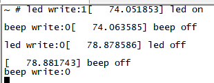
通过上述的所有流程,就实现了远程管理的所有流程,此时就可以通过串口工具测试下协议的执行效果,如下:
代码
完整的代码参考https://github.com/Imx6ull-app/remote_manage中lower_app中关于下位机的实现。