Introduction
In LTE the Downlink Shared Channel (DL-SCH) is a transport channel used for the transmission of user data, dedicated control and user-specific higher layer information and downlink system information. The Physical Downlink Shared Channel (PDSCH) is the physical channel that carries the DL-SCH coded data.

The cell-wide parameters and channel specific parameters
% Cell-wide Settings
% The cell-wide parameters are grouped into a single structure enb.
enb.NDLRB = 50;                 % Number of resource blocks
enb.CellRefP = 4;               % Cell-specific reference signal ports
enb.NCellID = 0;                % Cell ID
enb.CyclicPrefix = 'Normal';    % Normal cyclic prefix
enb.CFI = 2;                    % Length of control region
enb.DuplexMode = 'FDD';         % FDD duplex mode
enb.TDDConfig = 1;              % Uplink/Downlink configuration (TDD only)
enb.SSC = 4;                    % Special subframe configuration (TDD only)
enb.NSubframe = 0;              % Subframe number
% For the R.14 FDD RMC, there are two codewords, so the modulation scheme
% is specified as a cell array containing the modulation schemes of both
% codewords. If configuring for one codeword, the modulation scheme can be
% a character vector or a cell array with character vectors.
% It is also important to configure the TrBlkSizes parameter to have the
% correct number of elements as the intended number of codewords. The
% number of soft bits for the rate matching stage is decided by the UE
% category as specified in TS 36.306 Table 4.1-1. In this example, the
% transport block size is looked up from tables in TS 36.101 Annex A.3.4.

% DL-SCH Settings
TrBlkSizes = [11448; 11448];    % 2 elements for 2 codeword transmission
pdsch.RV = [0 0];               % RV for the 2 codewords
pdsch.NSoftbits = 1237248;      % No of soft channel bits for UE category 2
% PDSCH Settings
pdsch.TxScheme = 'SpatialMux';  % Transmission scheme used
pdsch.Modulation = {'16QAM','16QAM'}; % Symbol modulation for 2 codewords
pdsch.NLayers = 2;              % Two spatial transmission layers
pdsch.NTxAnts = 2;              % Number of transmit antennas
pdsch.RNTI = 1;                 % The RNTI value
pdsch.PRBSet = (0:enb.NDLRB-1)';% The PRBs for full allocation
pdsch.PMISet = 0;               % Precoding matrix index
pdsch.W = 1;                    % No UE-specific beamforming
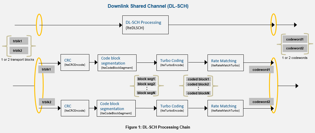
Downlink Shared Channel (DL-SCH) Processing
This section explains the DL-SCH transport channel coding. One transport block enters the processing chain every scheduled subframe (for spatial multiplexing schemes, there can be two transport blocks). The transport blocks get coded and rate matched to the PDSCH channel bit capacity. The PDSCH capacity depends on the PRB allocations, modulation scheme, and transmission scheme.
-
Transport Block CRC attachment: Error detection for the transport blocks are provided by a 24-bit CRC according to TS 36.212 Section 5.3.2.1.
-
Code block segmentation and code block CRC attachment: As shown in the figure 1 above, code block segmentation splits the input data bit vector into a cell array of code block segments (with filler bits and type-24B CRC appended as appropriate) according to the rules of TS 36.212 Section 5.3.2.2.
-
Channel Coding: The code blocks are individually turbo coded according to TS 36.212 Section 5.3.2.3.
-
Rate Matching and code block concatenation: The turbo coded blocks are then individually rate matched according to TS 36.212 Section 5.3.2.4 and the resulting rate matched blocks are concatenated as per TS 36.212 Section 5.3.2.5 to create a single codeword for transmission on the PDSCH.
Physical Downlink Shared Channel (PDSCH) Processing
One or two transport coded blocks (codewords) can be transmitted simultaneously on the PDSCH depending on the transmission scheme used (see TS 36.211 section 6.4). As shown in figure 2 above, the codewords undergo scrambling, modulation, layer mapping, precoding, optional UE-specific beamforming and resource element mapping. The size of the matrix precoded is N-by-P with N being the number of modulation symbols for one antenna port, and P being the number of transmission antennas.
-
Scrambling: Up to two codewords can be transmitted in a subframe and for each codeword, the bits are scrambled with a different scrambling sequence according to TS 36.211 Section 6.3.1. The scrambling sequence is initialized at the start of each subframe and depends on
RNTI,NCellID,NSubframeand the codeword index. -
Modulation: The scrambled codeword(s) is then symbol modulated using one of the modulation schemes ('QPSK', '16QAM', '64QAM' or '256QAM')
-
Layer Mapping: The complex modulated symbols are then mapped on to one or several layers according to the transmission scheme used (TS 36.211 Section 6.3.3). For single port (port 0, 5, 7 or 8), a single layer is used. For transmit diversity only one codeword is allowed and the number of layers (2 or 4) must be equal to the number of antenna ports used for the transmission of the physical channel. For spatial multiplexing 1 or 2 codewords can be transmitted on up to 8 layers. The number of layers is less than or equal to the number of antenna ports used for transmission of the physical channel.
-
Precoding: The precoding stage takes in the M-by-Layers matrix from the layer mapping stage and returns the matrix of size M-by-P for transmission on P antennas as defined in TS 36.211 Section 6.3.4. For single port (port 0, 5, 7 or 8), this stage is transparent and for transmit diversity, precoding is applied for 2 or 4 antenna ports. Precoding for spatial multiplexing depends on whether antenna ports with cell-specific reference signals ('SpatialMux', 'CDD' and 'MultiUser' transmission schemes) or antenna ports with UE-specific reference signals ('Port5', 'Port7-8', 'Port8' and 'Port7-14' transmission schemes) are used.
-
Mapping to Resource Elements: The complex modulated symbols are then mapped on to the resource elements as defined in TS 36.211 Section 6.3.5 to create the grid for transmission.
PDSCH Decoding
The decoding is the inverse of Physical Downlink Shared Channel (PDSCH) processing on the matrix of complex modulated PDSCH symbols, depending on cell-wide settings structure enb and channel-specific configuration structure pdsch. The channel inverse processing includes the deprecoding, layer demapping and codeword separation, soft demodulation and descrambling. The deprecoding is performed using matrix pseudo inversion of the precoding matrices. For applications involving propagation channels and/or noise, channel estimation and equalization is done on the received symbols before decoding.
DL-SCH Decoding
The Downlink Shared Channel (DL-SCH) decoding includes rate recovery, turbo decoding, block concatenation and CRC calculations. Returning the type-24A transport block CRC decoding result, type-24B code block set CRC decoding result, the HARQ process decoding state and provides parameterization for specifying the initial HARQ process state.
Selected Bibliography
-
3GPP TS 36.212 "Multiplexing and channel coding"
-
3GPP TS 36.211 "Physical channels and modulation"
-
3GPP TS 36.213 "Physical layer procedures"
-
3GPP TS 36.101 "User Equipment (UE) radio transmission and reception"
-
3GPP TS 36.306 "User Equipment (UE) radio access capabilities
- MathWorks