Introduction
This example shows how to measure the false detection probability and missed detection probability of Hybrid Automatic Repeat Request ACK (HARQ-ACK) multiplexed on the Physical Uplink Shared Channel (PUSCH).
Uplink Control Information (UCI) can be carried on the Physical Uplink Shared Channel (PUSCH) and may contain Hybrid Automatic Repeat Request ACK (HARQ-ACK) information. This example uses the LTE Toolbox to perform the "HARQ-ACK Multiplexed on PUSCH" conformance test specified in TS36.104, Section 8.2.4.1.
Two performance requirements are defined for HARQ-ACK multiplexed on the PUSCH:
-
ACK false detection probability is the probability that ACK is detected when data is only sent on symbols where HARQ-ACK information can be allocated.
-
The ACK missed detection probability is the conditional probability of not detecting an ACK when it was sent on PUSCH resources.
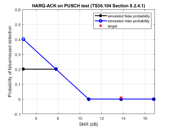
The conditions specified for this test are two receive antennas, normal cyclic prefix, ETU70 channel, using Fixed Reference Channel (FRC) A4-3. The target defined in TS 36.104, Section 8.2.4.1 for 1.4 MHz bandwidth (6RB) is a false detection probability and missed detection probability of 1% at 13.8 dB.
The test is run on a subframe by subframe basis at each SNR test point. For each subframe an uplink waveform is generated with and without ACK information, passed through a fading channel and the HARQ-ACK decoded. False detections and missed detections are recorded and the probability of error displayed for the range of SNRs tested.
Simulation Configuration
The example is executed for a simulation length of 1 frame at a number of SNRs including the required 13.8 dB at which the test requirements for false and missed detection rates (1% in each case) are to be achieved as per TS36.104, Table 8.2.4.1-1.
numSubframes = 10;  % Number of frames to simulate at each SNR
SNRdB = [4.8 7.8 10.8 13.8 16.8]; % SNR points to simulate
UE Configuration
To configure the transmitter, a few desired parameter fields are set in the structure frc, which is then passed to lteRMCUL which will set all the other required parameter fields.
frc.TotSubframes = 1;   % Total number of subframes to generate
frc.NCellID = 10;       % Cell identity
frc.RC = 'A4-3';        % FRC number

% Populate FRC configuration structure with default values for A4-3
frc = lteRMCUL(frc);
Propagation Channel Model Configuration
The propagation channel is configured via the structure chcfg, with settings per the test requirements. Note that the sampling rate of the propagation is determined from the sampling rate of the transmitted waveform, which can be established using lteSCFDMAInfo.
chcfg.NRxAnts = 2;               % Number of receive antennas
chcfg.DelayProfile = 'ETU';      % Delay profile
chcfg.DopplerFreq = 70;          % Doppler frequency
chcfg.MIMOCorrelation = 'Low';   % MIMO correlation
chcfg.Seed = 91;                 % Channel seed
chcfg.NTerms = 16;               % Oscillators used in fading model
chcfg.ModelType = 'GMEDS';       % Rayleigh fading model type
chcfg.InitPhase = 'Random';      % Random initial phases
chcfg.NormalizePathGains = 'On'; % Normalize delay profile power
chcfg.NormalizeTxAnts = 'On';    % Normalize for transmit antennas

% Set channel model sampling rate
info = lteSCFDMAInfo(frc);
chcfg.SamplingRate = info.SamplingRate;
hannel Estimator Configuration
The channel estimator is configured using the structure cec. An ETU delay profile causes the channel to change quickly over time. Therefore a small pilot averaging frequency window of 9 Resource Elements (REs) is used. The Demodulation Reference Signal (DRS) is contained in only one symbol per slot, therefore a time averaging window of 1 RE is used. This will not include any pilots from an adjacent slot when averaging.
cec.PilotAverage = 'UserDefined'; % Type of pilot averaging
cec.FreqWindow = 9;               % Frequency averaging windows in REs
cec.TimeWindow = 1;               % Time averaging windows in REs
cec.InterpType = 'cubic';         % Interpolation type
cec.Reference = 'Antennas';       % Reference for channel estimation
Loop for SNR Values
A loop is used to run the simulation for a set of SNR points, given by the vector SNRdB.
The noise added before SC-FDMA demodulation will be amplified by the IFFT. The amplification is the square root of the size of the IFFT ( ). To ensure that the power of the additive noise is normalized after demodulation to achieve the desired SNR, the desired noise power is divided by . In addition, as real and imaginary parts of the noise are created separately before being combined into complex Additive White Gaussian Noise (AWGN), the noise amplitude must be scaled by
  so the generated noise power is 1.
At each SNR test point the probability of false and missed detection is calculated. These probabilities are calculated on a subframe by subframe basis using the following steps:
-
Create Transmit Waveform: The Uplink Reference Measurement Channel (RMC) Tool lteRMCULTool is used to generate an uplink waveform containing random transport data and a HARQ-ACK bit in every odd subframe.
-
Noisy Channel Modeling: The waveform is passed through a fading channel and AWGN added.
-
Perform Synchronization and SC-FDMA Demodulation: The received symbols are synchronized to account for a combination of implementation delay and channel delay spread. The symbols are then SC-FDMA demodulated.
-
Perform Channel and Noise Power Spectral Density Estimation and Equalization: The channel and noise power spectral density are estimated and the received PUSCH symbols equalized.
-
Decode the PUSCH: The UpLink Shared Channel (UL-SCH) coding is determined and used to decode the PUSCH to recover the interleaved UL-SCH.
-
Recover UCI ACK Bit: Deinterleave the PUSCH and decode the HARQ-ACK information to recover the UCI HARQ-ACK bit and detect HARQ-ACK false or missed detection based on whether an HARQ-ACK bit was encoded in the transmitted subframe or not.
Analysis
Plot the simulated results against the target performance.

Reference,
1. TS36.104
2. MathWorks