Introduction
The SRS configuration is split into 2 parts - UE-specific and cell-specific. The UE-specific part describes the schedule and content of actual SRS transmissions for this UE. The cell-specific part describes the time schedule when any UE in the cell can transmit - the UE-specific schedule must be a subset of this schedule.
In this example the cell-specific SRS configuration has 5ms periodicity with an offset of 0 (signaled by srs.SubframeConfig = 3 as indicated in TS36.211, Table 5.5.3.3-1). The UE-specific SRS configuration has 10ms periodicity with an offset of 0 (signaled by srs.ConfigIdx = 7 as indicated in TS36.213, Table 8.2-1). The cell-specific configuration means that for this cell, two opportunities for SRS transmission exist within each frame, subframes 0 and 5. All UEs in the cell must shorten their Physical Uplink Control Channel (PUCCH) transmissions during these subframes to allow for SRS reception without interference, even if they are not transmitting SRS themselves. The UE-specific configuration means that this UE is configured to generate SRS only in subframe 0.
This example shows PUCCH transmission in all 10 subframes, with shortening in subframes 0 and 5, and an SRS transmission in subframe 0.
UE Configuration
ue = struct;
ue.NULRB = 15;                  % Number of resource blocks
ue.NCellID = 10;                % Physical layer cell identity
ue.Hopping = 'Off';             % Disable frequency hopping
ue.CyclicPrefixUL = 'Normal';   % Normal cyclic prefix
ue.DuplexMode = 'FDD';          % Frequency Division Duplex (FDD)
ue.NTxAnts = 1;                 % Number of transmit antennas
ue.NFrame = 0;                  % Frame number
PUCCH Configuration
pucch = struct;
% Vector of PUCCH resource indices, one per transmission antenna
pucch.ResourceIdx = 0:ue.NTxAnts-1;
pucch.DeltaShift = 1;               % PUCCH delta shift parameter
pucch.CyclicShifts = 0;             % PUCCH delta offset parameter
pucch.ResourceSize = 0;             % Size of resources allocated to PUCCH
SRS Configuration
srs = struct;
srs.NTxAnts = 1;        % Number of transmit antennas
srs.SubframeConfig = 3; % Cell-specific SRS period = 5ms, offset = 0
srs.BWConfig = 6;       % Cell-specific SRS bandwidth configuration
srs.BW = 0;             % UE-specific SRS bandwidth configuration
srs.HoppingBW = 0;      % SRS frequency hopping configuration
srs.TxComb = 0;         % Even indices for comb transmission
srs.FreqPosition = 0;   % Frequency domain position
srs.ConfigIdx = 7;      % UE-specific SRS period = 10ms, offset = 0
srs.CyclicShift = 0;    % UE-cyclic shift
Subframe Loop
The processing loop generates a subframe at a time. These are all concatenated to create the resource grid for a frame (10 subframes). The loop performs the following operations:
-
SRS Information: By calling lteSRSInfo we can get information related to SRS for a given subframe. The
IsSRSSubframefield of the structuresrsInforeturned from the lteSRSInfo call indicates if the current subframe (given byue.NSubframe) is a cell-specific SRS subframe (IsSRSSubframe = 1) or not (IsSRSSubframe = 0). The value of this field can be copied into theue.Shortenedfield. This ensures that the subsequent PUCCH generation will correctly respect the cell-specific SRS configuration for all subframes, omitting the last symbol of the PUCCH in the cell-specific SRS subframes.
-
PUCCH 1 Demodulation Reference Signal (DRS) Generation and Mapping: The DRS signal is located in the 3rd, 4th and 5th symbols of each slot and therefore never has the potential to collide with the SRS.
-
PUCCH 1 Generation and Mapping: Unlike the DRS, the PUCCH 1 transmission can occupy the last symbol of the subframe unless
ue.Shortened = 1. In this case the last symbol of the subframe will be left empty.
-
SRS Generation and Mapping: Here we generate and map the SRS according to the UE-specific SRS configuration. Both the lteSRSIndices and lteSRS functions use the fields
ue.NSubframeandsrs.ConfigIdxto determine if the current subframe is configured for SRS transmission; if not, the output of both functions is empty.
Subframe 0:
Transmitting shortened PUCCH
Transmitting SRS
Subframe 1:
Transmitting full-length PUCCH
Subframe 2:
Transmitting full-length PUCCH
Subframe 3:
Transmitting full-length PUCCH
Subframe 4:
Transmitting full-length PUCCH
Subframe 5:
Transmitting shortened PUCCH
Subframe 6:
Transmitting full-length PUCCH
Subframe 7:
Transmitting full-length PUCCH
Subframe 8:
Transmitting full-length PUCCH
Subframe 9:
Transmitting full-length PUCCH
Results
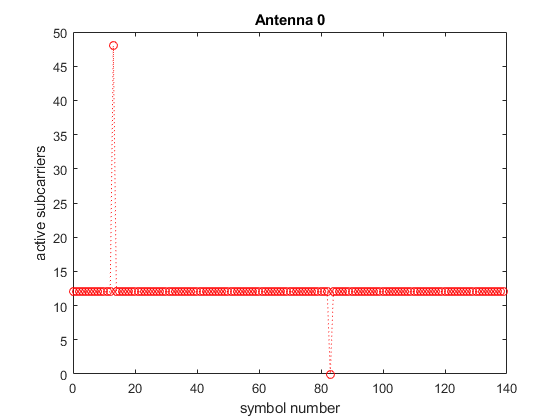
The figure produced shows the number of active subcarriers in each SC-FDMA symbol across the 140 symbols in txGrid. All SC-FDMA symbols contain 12 active subcarriers corresponding to the single resource block bandwidth of the PUCCH except:
-
symbol 13, the last symbol of subframe 0 which has 48 active subcarriers corresponding to an 8 resource block SRS transmission
-
symbol 83, the last symbol of subframe 5 which has 0 active subcarriers corresponding to the shortened PUCCH (last symbol empty) to allow for potential SRS transmission by another UE in this cell.
Plot the resource grid with the PUCCH at the band edges and the SRS comb transmission in subframe 0.

Further Exploration
SRS transmit antenna selection can be demonstrated by setting ue.NTxAnts = 2 and examining the subplots produced for each antenna; the SRS is transmitted on antenna 0 while the PUCCH is shortened on both (all) antennas. A pattern of antenna selection across this one-frame run can be shown by further configuring srs.SubframeConfig = 0 and srs.ConfigIdx = 0. This configures a cell-specific SRS configuration of 2ms periodicity with an offset of 0 (signaled by srs.SubframeConfig = 0) and also a UE-specific SRS configuration of 2ms periodicity with an offset of 0 (signaled by srs.ConfigIdx = 0). In this case an SRS is transmitted by this UE on even subframes, and the transmit antenna alternates with each transmission.
SRS transmission on multiple antennas using resource diversity can be shown by setting ue.NTxAnts = 2 and srs.NTxAnts = 2. In this case the SRS is always transmitted on both (all) antennas with orthogonal resources on each antenna.
Reference
1. TS36.211
2. TS36.213
3. MathWorks