注,转自互联网资源,仅供学习之用~~
Materials with Ogre 3D
Without materials, we can't add details to our scene and this chapter is going to give us an introduction to the vast field of using materials.
Materials are a really important topic and it's necessary to understand them to produce good-looking scenes. Materials are also an interesting topic of ongoing research, which has a lot of undiscovered possibilities.
In this chapter, we will:
‹‹Learn how to create our own materials
‹‹Apply textures to our quad
‹‹Understand better how the rendering pipeline works
‹‹Use the shader to create effects that are impossible without it
So let's get on with it...
Creating a white quad
In the previous chapter, we created our own 3D models with code. Now, we will use this to create a sample quad that we can experiment with.
Time for action – creating the quad
We will start with an empty application and insert the code for our quad into the createScene() function:
1. Begin with creating the manual object:
Ogre::ManualObject* manual = mSceneMgr->createManualObject("Quad");
manual->begin("BaseWhiteNoLighting", Ogre::RenderOperation::OT_TRIANGLE_LIST);
2. Create four points for our quad:
manual->position(5.0, 0.0, 0.0);
manual->textureCoord(0,1);
manual->position(-5.0, 10.0, 0.0);
manual->textureCoord(1,0);
manual->position(-5.0, 0.0, 0.0);
manual->textureCoord(1,1);
manual->position(5.0, 10.0, 0.0);manual->textureCoord(0,0);
3. Use indices to describe the quad:
manual->index(0);
manual->index(1);
manual->index(2);
manual->index(0);
manual->index(3);
manual->index(1);
4. Finish the manual object and convert it to a mesh:
manual->end();
manual->convertToMesh("Quad");
5. Create an instance of the entity and attach it to the scene using a scene node:
Ogre::Entity * ent = mSceneMgr->createEntity("Quad");
Ogre::SceneNode* node = mSceneMgr->getRootSceneNode()- >createChildSceneNode("Node1");
node->attachObject(ent);
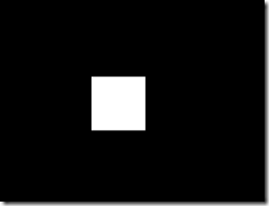
6. Compile and run the application. You should see a white quad.
What just happened?
We used our knowledge from the previous chapter to create a quad and attach to it a material that simply renders everything in white. The next step is to create our own material.
Creating our own material
Always rendering everything in white isn't exactly exciting, so let's create our first material.
Time for action – creating a material
Now, we are going to create our own material using the white quad we created.
1. Change the material name in the application from BaseWhiteNoLighting to MyMaterial1:
manual->begin("MyMaterial1", RenderOperation::OT_TRIANGLE_LIST);
2. Create a new file named Ogre3DBeginnersGuide.material in the media\ materials\scripts folder of our Ogre3D SDK.
3. Write the following code into the material file:
material MyMaterial1
{
technique
{
passMaterials with Ogre 3D [ 132 ]
{
texture_unit
{
texture leaf.png
}
}
}
}
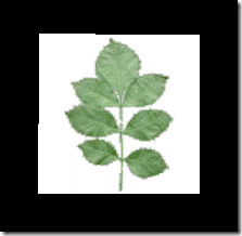
4. Compile and run the application. You should see a white quad with a plant drawn onto it.
What just happened?
We created our first material file. In Ogre 3D, materials can be defined in material files. To be able to find our material files, we need to put them in a directory listed in the resources. cfg, like the one we used. We also could give the path to the file directly in code using the ResourceManager, like we did in the preceding chapter with the map we loaded.
To use our material defined in the material file, we just had to use the name during the begin call of the manual object.
The interesting part is the material file itself.
Materials
Each material starts with the keyword material, the name of the material, and then an open curly bracket. To end the material, use a closed curly bracket—this technique should be very familiar to you by now. Each material consists of one or more techniques; a technique describes a way to achieve the desired effect. Because there are a lot of different graphic cards with different capabilities, we can define several techniques and Ogre 3D goes from top to bottom and selects the first technique that is supported by the user's graphic cards. Inside a technique, we can have several passes. A pass is a single rendering of your geometry. For most of the materials we are going to create, we only need one pass. However, some more complex materials might need two or three passes, so Ogre 3D enables us to define several passes per technique. In this pass, we only define a texture unit. A texture unit defines one texture and its properties. This time the only property we define is the texture to be used. We use leaf.png as the image used for our texture. This texture comes with the SDK and is in a folder that gets indexed by resources.cfg, so we can use it without any work from our side.
Have a go hero – creating another material
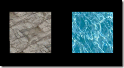
Create a new material called MyMaterial2 that uses Water02.jpg as an image.
Texture coordinates take two
In the previous chapter, we discussed that there are different strategies used when texture coordinates are outside the 0 to 1 range. Now, let's create some materials to see them in action.
Time for action – preparing our quad
We are going to use the quad from the previous example with the leaf texture material:
1. Change the texture coordinates of the quad from range 0 to 1 to 0 to 2. The quad code should then look like this:
manual->position(5.0, 0.0, 0.0);
manual->textureCoord(0,2);
manual->position(-5.0, 10.0, 0.0);
manual->textureCoord(2,0);
manual->position(-5.0, 0.0, 0.0);
manual->textureCoord(2,2);
manual->position(5.0, 10.0, 0.0);
manual->textureCoord(0,0);
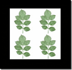
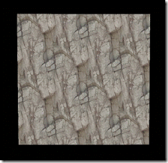
2. Now compile and run the application. Just as before, we will see a quad with a leaf texture, but this time we will see the texture four times.
What just happened?
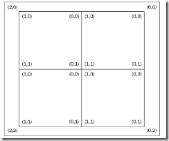
We simply changed our quad to have texture coordinates that range from zero to two. This means that Ogre 3D needs to use one of its strategies to render texture coordinates that are larger than 1. The default mode is wrap. This means each value over 1 is wrapped to be between zero and one. The following is a diagram showing this effect and how the texture coordinates are wrapped. Outside the corners, we see the original texture coordinates and inside the corners, we see the value after the wrapping. Also for better understanding, we see the four texture repetitions with their implicit texture coordinates.
We have seen how our texture gets wrapped using the default texture wrapping mode. Our plant texture shows the effect pretty well, but it doesn't show the usefulness of this technique. Let's use another texture to see the benefits of the wrapping mode.
Using the wrapping mode with another texture
Time for action – adding a rock texture
For this example, we are going to use another texture. Otherwise, we wouldn't see the effect of this texture mode:
1. Create a new material similar to the previous one, except change the used texture to: terr_rock6.jpg:
material MyMaterial3
{
technique
{
pass
{
texture_unit
texture terr_rock6.jpg
}
}
}
}
2. Change the used material from MyMaterial1 to MyMaterial3:
manual->begin("MyMaterial3", RenderOperation::OT_TRIANGLE_LIST)
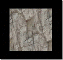
3. Compile and run the application. You should see a quad covered in a rock texture.
What just happened?
This time, the quad seems like it's covered in one single texture. We don't see any obvious repetitions like we did with the plant texture. The reason for this is that, like we already know, the texture wrapping mode repeats. The texture was created in such a way that at the left end of the texture, the texture is started again with its right side and the same is true for the lower end. This kind of texture is called seamless. The texture we used was prepared so that the left and right side fit perfectly together. The same goes for the upper and lower part of the texture. If this wasn't the case, we would see instances where the texture is repeated.
Using another texture mode
We have seen the effect and usage for the wrapping mode. Now, let's look into another texture mode called clamping.
Time for action – adding a rock texture
We are going to use the same project and just create a new material:
1. Create a new material called MyMaterial4, which is identical to the previous material:
material MyMaterial4
{
technique
{
pass
{
texture_unit
{
texture terr_rock6.jpg
}
}
}
}
2. Inside the texture unit block, add a line that tells Ogre 3D to use the clamp mode:
tex_address_mode clamp
3. Change the material we use for our quad from MyMaterial3 to MyMaterial4:
manual->begin("MyMaterial4", RenderOperation::OT_TRIANGLE_LIST);
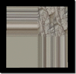
4. Compile and run the application. You should see the stone texture from before in the upper-right corner of the quad. The other three parts of the quad should be lines of different colors.
What just happened?
We changed the texture mode to clamp. This mode uses the border pixels of a texture to fill all texture coordinates that are greater than 1. In practice, this means the border of an image gets stretched over the model; we can see this effect in the preceding image.
Scrolling a texture
We have seen several texture modes, but this is only one attribute a material file can have. Now, we are going to use another attribute that can also be quite useful.
Time for action – preparing to scroll a texture
This time, we are going to change our quad to see the effect of the new material:
1. Change the used material to MyMaterial8 and also change the texture coordinates from 2 to 0.2:
manual->begin("MyMaterial8", RenderOperation::OT_TRIANGLE_LIST);
manual->position(5.0, 0.0, 0.0);
manual->textureCoord(0.0,0.2);
manual->position(-5.0, 10.0, 0.0);
manual->textureCoord(0.2,0.0);
manual->position(-5.0, 0.0, 0.0);
manual->textureCoord(0.2,0.2);
manual->position(5.0, 10.0, 0.0);
manual->textureCoord(0.0,0.0);
2. Now create the new material MyMaterial8 in the material file. This time, we don't need any texture mode; just use the texture terr_rock6.jpg:
material MyMaterial8
{
technique
{
pass
{
texture_unit
{
texture terr_rock6.jpg
}
}
}
}
3. Compile and run the application. You should see a part of the stone texture that we had seen before.
What just happened?
We are only seeing a part of the texture because our quad only has a texture coordinate that is going up to 0.2; this means four-fifths of the texture isn't rendered onto our quad. Everything that has happened in this Time for action should be easy to understand, as it's just a repetition of the stuff we learned in this chapter up until now. If necessary, read the chapter again.
Time for action – scrolling a texture
Now that we have prepared our quad, let's scroll the texture:
1. Add the following line into the texture block of the material to scroll the texture:
scroll 0.8 0.8
2. Compile and run the application. This time, you should see a different part of the texture.
What just happened?
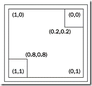
The scroll attribute changes the texture coordinates with the given offset. The following is a diagram showing the effect of scrolling. The upper-right corner was the first part of the texture we rendered and the lower-left corner was the part of the texture we rendered with the scroll applied.
This attribute can be used to change the texture coordinates without the need for changing the UV coordinates of a model itself.
【利用这个属性,将来可以用于改变给定mesh中uv坐标】
Animated scrolling
Being able to scroll the texture in the material isn't exactly breathtaking, but it can help to save some time in comparison to retexturing a complete model. Let's add a bit of dynamic scrolling.
Time for action – adding animated scrolling
We can also make the scrolling of the texture dynamic. Let's do it:
1. Create a new material and change the scroll attribute to animated scrolling:
scroll_anim 0.01 0.01
2. Remember to also change the used material of the manual object; otherwise, you won't see any changes.
3. Compile and run the application. When you look carefully, you should see the texture moving from the upper-right to the lower-left corner. I can't show a picture of this because printing isn't yet able to show animations (maybe in the future).
What just happened?
We used another attribute to make the texture scroll. Besides the name, this attribute is almost similar to the scroll attribute, with the small, but important, difference that now the offset we set is per second.
There are many more attributes that we can use for manipulating a texture. A complete list can be found at http://www.ogre3d.org/docs/manual/manual_17.html#SEC9.
Inheriting materials
Before we touch more complex topics like shaders, we will try inheriting from materials.
Time for action – inheriting from a material
We will create two new materials and one new quad. We will also change how our quad is defined:
1. For this example, we need a quad that simply displays one texture. Change the quad definition to use only texture coordinates between 0 and 1 and remember to change the used material to MyMaterial11, which we will create soon:
manual->begin("MyMaterial11", RenderOperation::OT_TRIANGLE_LIST);
manual->position(5.0, 0.0, 0.0);
manual->textureCoord(0.0,1.0);
manual->position(-5.0, 10.0, 0.0);
manual->textureCoord(1.0,0.0);
manual->position(-5.0, 0.0, 0.0);
manual->textureCoord(1.0,1.0);
manual->position(5.0, 10.0, 0.0);
manual->textureCoord(0.0,0.0);
manual->index(0);
manual->index(1);
manual->index(2);
manual->index(0);
manual->index(3);
manual->index(1);
manual->end();
2. The new material will use the rock texture and use the attribute rotate_anim, which rotates the texture with the given speed. But the most important thing is to name the texture unit texture1:
material MyMaterial11
{
technique
{
pass
{
texture_unit texture1
{
texture terr_rock6.jpg
rotate_anim 0.1
}}
}
}
3. Now create a second quad and translate it 15 units on the x-axis so that it doesn't intersect with the first quad. Also use the setMaterialName() function to change the material used by the entity to MyMaterial12:
ent = mSceneMgr->createEntity("Quad");
ent->setMaterialName("MyMaterial12");node = mSceneMgr- >getRootSceneNode()->createChildSceneNode("Node2",Ogre::Vect or3(15,0,0));
node->attachObject(ent);
4. The last thing to do is to create MyMaterial12. We will inherit from MyMaterial11 and set the texture alias to another texture that we want to use:
material MyMaterial12 : MyMaterial11
{
set_texture_alias texture1 Water02.jpg
}
5. Compile and run the application, and you should see two quads with rotating textures—one is a rock texture and the other one is a water texture.
What just happened?
We created two quads, each with its own material. Steps 1 and 2 just modified the quad to only use texture coordinates in the range of [0,1]. In step 2, we created our material for the quad and used the new attribute rotate_anim x, which rotates the texture x turns per second—nothing fancy. Also we gave the texture unit the name texture1; we need this name later. In step 3, we created another instance of the quad and used the setMaterialName() function to change the material used by the entity. The important part was step 4. Here we created a new material by using inheritance, a concept which should be familiar. The syntax is the same as in C++, NewName : ParentName. In this case, MyMaterial12 inherits from MyMaterial11. Then we use the attribute set_texture_ alias that binds the texture Water02.jpg to the texture unit texture1. In this case, we replace terr_rock6.jpg with Water02.jpg. Because this is the only change we wanted to make with our new material, we can stop here. ,
The use of texture aliases enables us to create a lot of materials that only differ in the used texture without the need to write each material from the ground up, and we all know that duplication should always be avoided, if possible.
We have covered a lot of things about materials, but there is a lot more that we can do. We have covered the basics and with the help of the documentation, it should be possible to understand most of the other attributes that can be used in materials. Just take a look here http://www.ogre3d.org/docs/manual/manual_14.html#SEC23. We will now go a bit deeper and learn how to program our graphics card with the so-called shaders.
Fixed Function Pipeline and shaders
In this chapter, we have used the so-called Fixed Function Pipeline. This is the rendering pipeline on the graphics card that produces those nice shiny pictures we love looking at. As the prefix Fixed suggests, there isn't a lot of freedom to manipulate the Fixed Function Pipeline for the developer. We can tweak some parameters using the material files, but nothing fancy. That's where shaders can help fill the gap. Shaders are small programs that can be loaded onto the graphics card and then function as a part of the rendering process. These shaders can be thought of as little programs written in a C-like language with a small, but powerful, set of functions. With shaders, we can almost completely control how our scene is rendered and also add a lot of new effects that weren't possible with only the Fixed Function Pipeline.
Render Pipeline
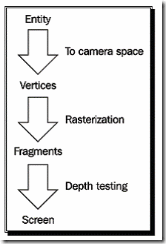
To understand shaders, we need to first understand how the rendering process works as a whole. When rendering, each vertex of our model is translated from local space into camera space, then each triangle gets rasterized. This means, the graphics card calculates how to represent the model in an image. These image parts are called fragments. Each fragment is then processed and manipulated. We could apply a specific part of a texture to this fragment to texture our model or we could simply assign it a color when rendering a model in only one color. After this processing, the graphics card tests if the fragment is covered by another fragment that is nearer to the camera or if it is the fragment nearest to the camera. If this is true, the fragment gets displayed on the screen. In newer hardware, this step can occur before the processing of the fragment. This can save a lot of computation time if most of the fragments won't be seen in the end result. The following is a very simplified graph showing the pipeline:.
With almost each new graphics card generation, new shader types were introduced. It began with vertex and pixel/fragment shaders. The task of the vertex shader is to transform the vertices into camera space, and if needed, modify them in any way, like when doing animations completely on the GPU. The pixel/fragment shader gets the rasterized fragments and can apply a texture to them or manipulate them in other ways, for example, for lighting models with an accuracy of a pixel. There are also other shader stages, such as Geometry shaders, but we won't discuss them in this book because they are pretty new, not widely supported, and also are out of the scope of this book.
Time for action – our first shader application
Let's write our first vertex and fragment shaders:
1. In our application, we only need to change the used material. Change it to MyMaterial13. Also remove the second quad:
manual->begin("MyMaterial13", RenderOperation::OT_TRIANGLE_LIST);
2. Now we need to create this material in our material file. First, we are going to define the fragment shader. Ogre 3D needs five pieces of information about the shader:
‰‰The name of the shader
‰‰In which language it is written
‰‰In which source file it is stored
‰‰How the main function of this shader is called
‰‰In what profile we want the shader to be compiled
3. All this information should be in the material file:
fragment_program MyFragmentShader1 cg
{
source Ogre3DBeginnersGuideShaders.cg
entry_point MyFragmentShader1
profiles ps_1_1 arbfp1
}
4. The vertex shader needs the same parameter, but we also have to define a parameter that is passed from Ogre 3D to our shader. This contains the matrix that we will use for transforming our quad into camera space:
vertex_program MyVertexShader1 cg
{
source Ogre3DBeginnerGuideShaders.cg
entry_point MyVertexShader1
profiles vs_1_1 arbvp1
default_params
{
param_named_auto worldViewMatrix worldviewproj_matrix
}
}
5. The material itself just uses the vertex and fragment shader names to reference them:
material MyMaterial13
{
technique
{
pass
{
vertex_program_ref MyVertexShader1
{
}
fragment_program_ref MyFragmentShader1
{
}
}
}
}
6. Now we need to write the shader itself. Create a file named Ogre3DBeginnersGuideShaders.cg in the media\materials\programs folder of your Ogre 3D SDK.
7. Each shader looks like a function. One difference is that we can use the out keyword to mark a parameter as an outgoing parameter instead of the default incoming parameter. The out parameters are used by the rendering pipeline for the next rendering step. The out parameters of a vertex shader are processed and then passed into the pixel shader as an in parameter. The out parameter from a pixel shader is used to create the final render result. Remember to use the correct name for the function; otherwise, Ogre 3D won't find it. Let's begin with the fragment shader because it's easier:
void MyFragmentShader1(out float4 color: COLOR)
8. The fragment shader will return the color blue for every pixel we render:
{
color = float4(0,0,1,0);
}
9. That's all for the fragment shader; now we come to the vertex shader. The vertex shader has three parameters—the position for the vertex, the translated position of the vertex as an out variable, and as a uniform variable for the matrix we are using for the translation:
void MyVertexShader1(
float4 position : POSITION,
out float4 oPosition : POSITION,
uniform float4x4 worldViewMatrix)
10. Inside the shader, we use the matrix and the incoming position to calculate the outgoing position:
{
oPosition = mul(worldViewMatrix, position);
}
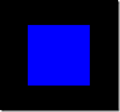
11. Compile and run the application. You should see our quad, this time rendered in blue.
What just happened?
Quite a lot happened here; we will start with step 2. Here we defined the fragment shader we are going to use. As discussed before, Ogre 3D needs five pieces of information for a shader. We define a fragment shader with the keyword fragment_program, followed by the name we want the fragment program to have, then a space, and at the end, the language in which the shader will be written. As for programs, shader code was written in assembly and in the early days, programmers had to write shader code in assembly because there wasn't another language to be used. But also, as with general programming language, soon there came high-level programming to ease the pain of writing shader code. At the moment, there are three different languages that shaders can be written in: HLSL, GLSL, and CG. The shader language HLSL is used by DirectX and GLSL is the language used by OpenGL. CG was developed by NVidia in cooperation with Microsoft and is the language we are going to use. This language is compiled during the start up of our application to their respective assembly code. So shaders written in HLSL can only be used with DirectX and GLSL shaders with OpenGL. But CG can compile to DirectX and OpenGL shader assembly code; that's the reason why we are using it to
That's two of the five pieces of information that Ogre 3D needs. The other three are given in the curly brackets. The syntax is like a property file—first the key and then the value. One key we use is source followed by the file where the shader is stored. We don't need to give the full path, just the filename will do, because Ogre 3D scans our directories and only needs the filename to find the file.
Another key we are using is entry_point followed by the name of the function we are going to use for the shader. In the code file, we created a function called MyFragmentShader1 and we are giving Ogre 3D this name as the entry point for our fragment shader. This means, each time we need the fragment shader, this function is called. The function has only one parameter out float4 color : COLOR. The prefix out signals that this parameter is an out parameter, meaning we will write a value into it, which will be used by the render pipeline later on. The type of this parameter is called float4, which simply is an array of four float values. For colors, we can think of it as a tuple (r,g,b,a) where r stands for red, g for green, b for blue, and a for alpha: the typical tuple to description colors. After the name of the parameter, we got a : COLOR. In CG, this is called a semantic describing for what the parameter is used in the context of the render pipeline. The parameter :COLOR tells the render pipeline that this is a color. In combination with the out keyword and the fact that this is a fragment shader, the render pipeline can deduce that this is the color we want our fragment to have.
The last piece of information we supply uses the keyword profiles with the values ps_1_1 and arbfp1. To understand this, we need to talk a bit about the history of shaders. With each generation of graphics cards, a new generation of shaders have been introduced. What started as a fairly simple C-like programming language without even IF conditions are now really complex and powerful programming languages. Right now, there are several different versions for shaders and each with a unique function set. Ogre 3D needs to know which of these versions we want to use. ps_1_1 means pixel shader version 1.1 and arbfp1 means fragment program version 1. We need both profiles because ps_1_1 is a DirectX specific function set and arbfp1 is a function subset for OpenGL. We say we are cross platform, but sometimes we need to define values for both platforms.
All subsets can be found at http://www.ogre3d.org/docs/manual/manual_18.html. That's all needed to define the fragment shader in our material file. In step 3, we defined our vertex shader. This part is very similar to the fragment shader definition code; the main difference is the default_ params block. This block defines parameters that are given to the shader during runtime. param_named_auto defines a parameter that is automatically passed to the shader by Ogre 3D. After this key, we need to give the parameter a name and after this, the value keyword we want it to have. We name the parameter worldViewMatrix; any other name would also work, and the value we want it to have has the key worldviewproj_matrix. This key tells Ogre 3D we want our parameter to have the value of the WorldViewProjection matrix. This matrix is used for transforming vertices from local into camera space. A list of all keyword values can be found at http://www.ogre3d.org/docs/manual/manual_23. html#SEC128.
How we use these values will be seen shortly.
Step 4 used the work we did before. As always, we defined our material with one technique and one pass; we didn't define a texture unit but used the keyword vertex_program_ref. After this keyword, we need to put the name of a vertex program we defined, in our case, this is MyVertexShader1. If we wanted, we could have put some more parameters into the definition, but we didn't need to, so we just opened and closed the block with curly brackets. The same is true for fragment_program_ref.
Writing a shader
Now that we have defined all necessary things in our material file, let's write the shader code itself. Step 6 defines the function head with the parameter we discussed before, so we won't go deeper here. Step 7 defines the function body; for this fragment shader, the body is extremely simple. We created a new float4 tuple (0,0,1,0), describes the color blue and assigns this color to our out parameter color. The effect is that everything that is rendered with this material will be blue.
There isn't more to the fragment shader, so let's move on to the vertex shader. Step 8 defines the function header. The vertex shader has 3 parameters— two are marked as positions using CG semantics and the other parameter is a 4x4 matrix using float4 as values named worldViewMatrix. Before the parameter type definition, there is the keyword uniform.
Each time our vertex shader is called, it gets a new vertex as the position parameter input, calculates the position of this new vertex, and saves it in the oPosition parameter. This means with each call, the parameter changes. This isn't true for the worldViewMatrix. The keyword uniform denotes parameters that are constant over one draw call. When we render our quad, the worldViewMatrix doesn't change while the rest of the parameters are different for each vertex processed by our vertex shader. Of course, in the next frame, the worldViewMatrix will probably have changed.
Step 9 creates the body of the vertex shader. In the body, we multiply the vertex that we got with the world matrix to get the vertex translated into camera space. This translated vertex is saved in the out parameter to be processed by the rendering pipeline. We will look more closely into the render pipeline after we have experimented with shaders a bit more.
Texturing with shaders
We have painted our quad in blue, but we would like to use the previous texture.
Time for action – using textures in shaders
1. Create a new material named MyMaterial14. Also create two new shaders named MyFragmentShader2 and MyVertexShader2. Remember to copy the fragment and vertex program definitions in the material file. Add to the material file a texture unit with the rock texture:
texture_unit
{
texture terr_rock6.jpg
}
2. We need to add two new parameters to our fragment shader. The first is a two tuple of floats for the texture coordinates. Therefore, we also use the semantic to mark the parameter as the first texture coordinates we are using. The other new parameter is of type sampler2D, which is another name for texture. Because the texture doesn't change on a per fragment basis, we mark it as uniform. This keyword indicates that the parameter value comes from outside the CG program and is set by the rendering environment, in our case, by Ogre 3D:
void MyFragmentShader2(float2 uv : TEXCOORD0,
out float4 color : COLOR,
uniform sampler2D texture)
3. In the fragment shader, replace the color assignment with the following line:
color = tex2D(texture, uv);
4. The vertex shader also needs some new parameters—one float2 for the incoming texture coordinates and one float2 as the outgoing texture coordinates. Both are our TEXCOORD0 because one is the incoming and the other is the outgoing TEXCOORD0:
void MyVertexShader2(
float4 position : POSITION,
out float4 oPosition : POSITION,
float2 uv : TEXCOORD0,
out float2 oUv : TEXCOORD0,
uniform float4x4 worldViewMatrix)
5. In the body, we calculate the outgoing position of the vertex:
oPosition = mul(worldViewMatrix, position);
6. For the texture coordinates, we assign the incoming value to the outgoing value:
oUv = uv;
7. Remember to change the used material in the application code, and then compile and run it. You should see the quad with the rock texture.
What just happened?
Step 1 just added a texture unit with the rock texture, nothing fancy. Step 2 added a float2 for saving the texture coordinates; also we are using sampler2D for the first time. sampler2D is just the name for a two-dimensional texture lookup function, and because it doesn't change per fragment and comes from outside the CG program, we declared it uniform. Step 3 used the tex2D function, which takes a sampler2D and float2 as the input parameter and returns a color as float4. This function uses the float2 as the position to retrieve a color from the sampler2D object and returns this color. Basically, it's just a lookup in the texture for the given coordinates. Step 4 added two texture coordinates to the vertex shader—one as incoming and one as outgoing. Step 5 assigned the incoming to the outgoing parameter. The magic happens in the render pipeline.
What happens in the render pipeline?
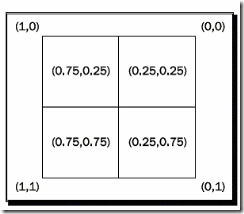
Our vertex shader gets each vertex and transforms it into camera space. After all vertices have gone through this transformation, the render pipeline sees which vertices form a triangle and then rasterizes them. In this process, the triangles get split into fragments. Each fragment is a candidate for becoming pixels on the screen. It will become pixels if it's not covered by another fragment and therefore can't be seen. During this process, the render pipeline interpolates the vertex data like texture coordinates over each fragment. After this process, each fragment has its own texture coordinate and we used this to look up the color value from the texture. The following image is an example of a quad, which is represented by four fragments. Each fragment has its own texture coordinates. It also shows how we can imagine the texture coordinates, related to the pixels. In the real world, this depends on the render pipeline and can change, but this is a helpful model we can think with, even if it's not 100 percent accurate.
The same interpolation is used when we assign each vertex a color. Let's investigate this effect a bit more.
Have a go hero – combining color and texture coordinates
Create a new vertex and fragment shader called MyVertexShader3 and MyFragmentShader3 respectively. The fragment shader should render everything in green and the vertex shader should calculate the position of the vertex in camera space and simply pass the texture coordinates to the fragment shader. The fragment shader doesn't do anything with them yet, but we will need them later.
Interpolating color values
To see the effect of interpolation better, let's replace the texture with colors.
Time for action – using colors to see interpolation
To see how color interpolation works we need to change our code a bit.
1. Again, copy the material and make sure to adjust all names.
2. The only thing we need to change in the material is that we don't need a texture unit. We can just delete it.
3. In the application code, we need to replace the textureCoord() with color():
manual->position(5.0, 0.0, 0.0);
manual->color(0,0,1);
manual->position(-5.0, 10.0, 0.0);
manual->color(0,1,0);
manual->position(-5.0, 0.0, 0.0);
manual->color(0,1,0);
manual->position(5.0, 10.0, 0.0);
manual->color(0,0,1);
4. The vertex shader also needs some adjustments. Replace the two texture coordinate parameters with color parameters and also change the assignment line:
void MyVertexShader4(
float4 position : POSITION,
out float4 oPosition : POSITION,
float4 color :COLOR,
out float4 ocolor :COLOR,
uniform float4x4 worldViewMatrix)
{
oPosition = mul(worldViewMatrix, position);
ocolor = color;
· }
5. The fragment shader now has two color parameters—one incoming and one outgoing:
void MyFragmentShader4( float4 color : COLOR,
out float4 oColor : COLOR)
{
oColor = color;
}
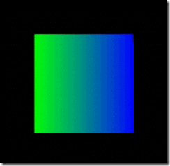
6. Compile and run the application. You should see the quad with the right side blue and the left side green and the colors should fade into each other in between.
What just happened?
In step 3, we saw another function of the manual object, namely, adding color to a vertex using three float values for red, green, and blue. Step 4 replaced the texture coordinates with color parameters—this time we wanted colors not textures. The same is true for step 5. This example wasn't really difficult or exciting, but it shows how interpolation works. This gives us a better understanding of how the vertex and fragment shader also work together.
Replacing the quad with a model
The quad, as an object for experimentation, gets a bit boring, so let's replace it with the Sinbad model.
Time for action – replacing the quad with a model
Using the previous code we will now use Sinbad instead of a quad.
1. Delete all the code for the quad; just leave the scene node creation code in place.
2. Create an instance of Sinbad.mesh, attach it to the scene node, and use the MaterialManager to set the material of the entity to MyMaterial14:
void createScene()
{
Ogre::SceneNode* node = mSceneMgr->getRootSceneNode()- >createChildSceneNode("Node1");
Ogre::Entity* ent = mSceneMgr->createEntity("Entity1","Sinbad. mesh");
ent->setMaterialName("MyMaterial14");
node->attachObject(ent);
}
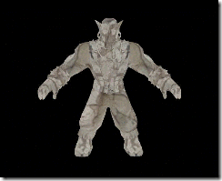
3. Compile and run the application; because MyMaterial14 uses the rock texture, Sinbad will be made out of rock.
What just happened?
Everything that has happened here should be familiar to you. We created an instance of a model, attached it to a scene node, and changed the material to MyMaterial14.
Making the model pulse on the x-axis
Up until now, we only worked with the fragment shader. Now it's time for the vertex shader.
Time for action – adding a pulse
Adding a pulse to our model is quite easy and only needs some changes to our code.
1. This time, we only need a new vertex shader because we are going to use the existing fragment shader. Create a new vertex shader named MyVertexShader5 and use it in the new material MyMaterial17, but use MyFragmentShader2 because this shader only textures our model and nothing more:
material MyMaterial17
{
technique
{
pass
{
vertex_program_ref MyVertexShader5
{
}
fragment_program_ref MyFragmentShader2
{
}
texture_unit
{
texture terr_rock6.jpg
}
}
}
}
2. The new vertex shader is the same as the ones we've seen before; just add a new parameter in the default_params block called pulseTime that gets the value from the time keyword:
vertex_program MyVertexShader5 cg
{
source Ogre3DBeginnerGuideShaders.cg
entry_point MyVertexShader5
profiles vs_1_1 arbvp1
default_params
{
param_named_auto worldViewMatrix worldviewproj_matrix
param_named_auto pulseTime time
}
}
3. We don't need to change anything in the application itself. The only thing left to do is to create the new vertex shader. MyVertexShader5 is based on MyVertexShader3. Just add a new line that multiplies the x value of the oPosition variable with (2+sin(pulseTime)):
void MyVertexShader5( uniform float pulseTime,
float4 position : POSITION,
out float4 oPosition : POSITION,
float2 uv : TEXCOORD0,
out float2 oUv : TEXCOORD0,
uniform float4x4 worldViewMatrix)
{
oPosition = mul(worldViewMatrix, position);
oPosition.x *= (2+sin(pulseTime));
oUv = uv;
}
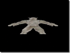
4. Compile and run the application. You should see Sinbad pulsing on the x-axis between his normal width and the threefold of his width.
What just happened?
We made the model pulse on the x-axis. We needed a second parameter for the vertex shader, which contains the current time. We used the sine of the time with two added to get a value between 1 and 3, with which we multiplied the x part of each translated vertex of the model. In action, this changes the position of each single vertex in each frame a bit, creating the effect of pulsing. Using this technique, we can practically pass any data into a shader to modify its behavior. This is the basis for a lot of effects used in games.
Summary
We learned a lot in this chapter about materials and Ogre 3D.
Specifically, we covered:
‹‹How to create new materials
‹‹How to apply textures to an entity using a material
‹‹How to create shaders and refer to them in materials
‹‹How the render pipeline works and how to modify the geometry of models using the vertex shader
In the next chapter, we are going to create post-processing effects to improve the visual quality of our scene or create completely new visual styles.
