1. 前言
一颗芯片最主要的就是CPU核了,处理CPU Core之外,还存在很多其他IP,包括Graphical、Multimedia、Memory Controller、USB Controller等等。
ARM products列出了主要产品,其中Architecture和Processors需要重点关注。
Architecture扩展的四大领域:
更具不同的应用场景将处理器分为三大配置:
|
同样也有对应的A、R、M三大类处理器:
Cortex-A、Cortex-R、Cortex-M,重点看Cortex-A系列:Cortex-A75、Cortex-A73、Cortex-A72、Cortex-A57、Cortex-A55、Cortex-A53、Cortex-A35、Cortex-A32、Cortex-A17、Cortex-A15、Cortex-A9、Cortex-A8、Cortex-A7、Cortex-A5。
其他还包括Corelink、GIC、MMU、DMA、L2 Cache、Memory、IO。
2. Cortex-A53处理器技术参考手册(ARM Cortex-A53 Processor Technical Reference Manual)
官方文档位置:https://developer.arm.com/docs/ddi0500/latest/preface
本书阅读笔记目录如下:
9 Generic Interrupt Controller CPU Interface
2 Functional Description
2.1 About the Cortex-A53 processor functions
Cortex-A53处理的的框架图:
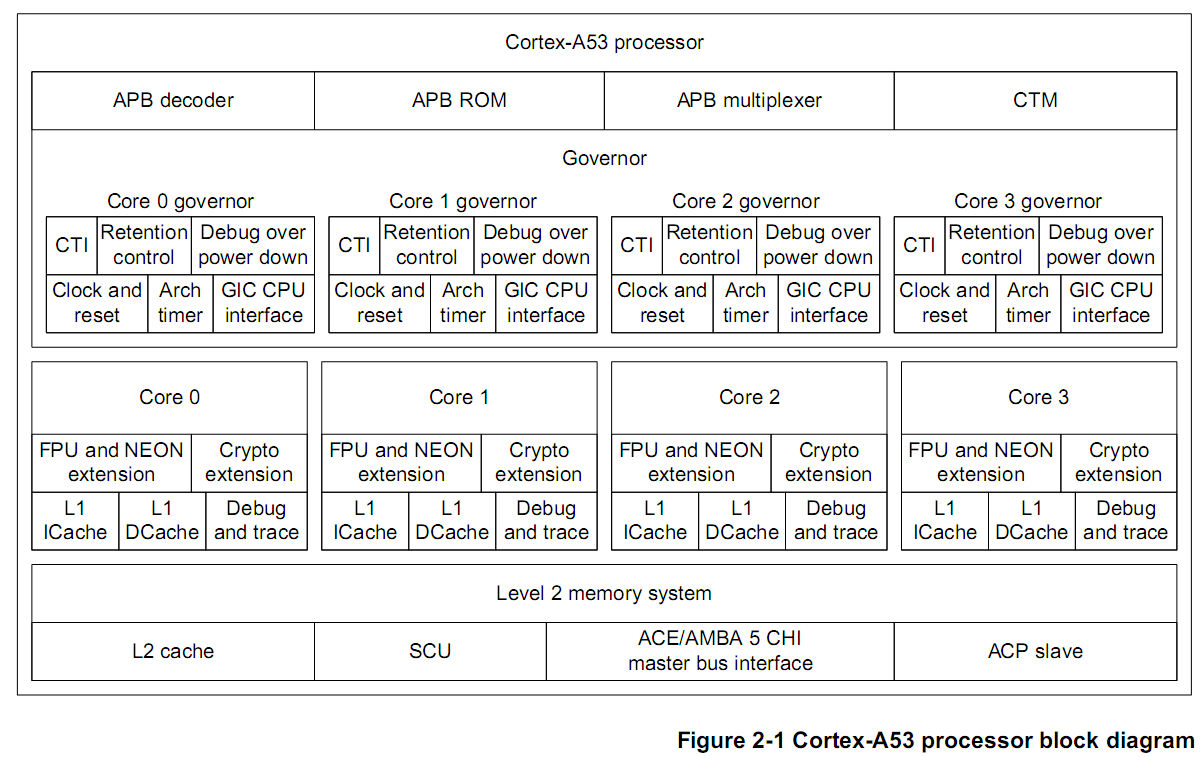
Core[n]包括
2.2 Interfaces
2.3 Clocking and resets
2.3.1 Clocks
整个A53处理器公用一个时钟输入CLKIN,所有核和SCU使用CLKIN分发的时钟。
CLKIN经过一些使能信号转换成不同频率的时钟,有的CLKIN:XXX频比是3:1,有的是1:1。
PCLKENDBG-->PCLK
ACLKENM-->ACLKM
ACLKENS-->ACLKS
SCLKEN-->SCLK
ATCLKEN-->ATCLK
CNTCLKEN-->CNTCLK
2.3.2 Input synchronization
A53包含以下5个低有效复位信号“
nCPUPORESET[CN:0]
nCORERESET[CN:0]
nPRESETDBG
nL2RESET
nMBISTRESET
这5种复位信号产生多种如下组合:
2.4 Power management
从Figure 2-1框架图中可以看出Core<n>包括L1 Cache、FPU、NEON、Crypto、Debug and trace等。核间公用的包括L2 cache、SCU等。
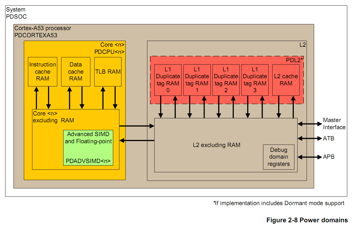
将其划分为四个Power Domain如下:
| Power Domain | Description | More |
| PDCORTEXA53 |
This includes the SCU, the optional L2 cache controller, and debug registers described as being in the |
此电源域应该是包括SCU、L2 cache除了RAM部分和debug。 |
| PDL2 | This includes the L2 data RAM, L2 tag RAM, L2 victim RAM, and the SCU duplicate tag RAM. | 主要是L2 cache和SCU里面的RAM部分。 |
| PDCPU<n> |
This includes the optional Advanced SIMD and floating-point Extension, the L1 TLB, L1 processor |
此部分是单独Core内部的。 |
| PDCPUADVSIMD<n> | This represents the Advanced SIMD and floating-point block of core n. | 仅包括某个Core内部的Advanced SIMD和FPU。 |
下图每种颜色对应一种电源域,可以看出哪些器件在上面四中电源域中的一种。
2.4.2 Power Modes
在上面介绍了四种电源域,这四种电源域可以单独被打开或者关闭。但并不是所有的组合都是合法或有效的。
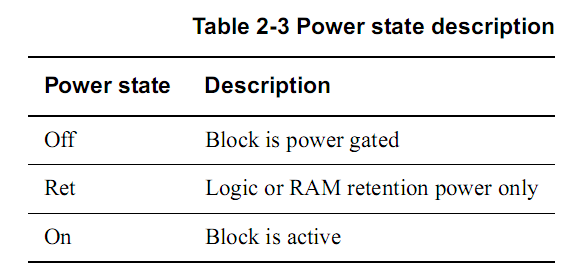
每个电源域至此后的状态有:
那么芯片支持哪几种组合的状态呢?分为两大类:处理器支持的功耗状态和核支持的功耗状态,其中核支持的功耗状态在核间是独立的。
处理器功耗状态:
Processor off所有的电源域都关闭’
L2 Cache Dormance Mode只有PDL2处于On/Ret状态。
其他都是Processor On,然后L2和Core的不同组合。

核的工作状态除了Core off,必须要在PDCORTEXA53 On和PDL2 On/Ret转改下才有意义。

基于上面的处理器功耗状态和核功耗状态的组合,有下面的功耗模式。
Normal state
处理器所有功能都可用,A53通过门控时钟和门控来关闭未用功能块。
Standby state(P42)
Standby state还包括三种情况Core WFI、Core WFE和L2 WFI。
Core WFI:通过关闭核中大部分时钟但保持核供电以进入低功耗模式。软件通过执行WFI指令使核进入WFI低功耗模式。
WFI退出条件:a reset、
Core WFE:也是通过关闭核中大部分时钟但保留核供电来达到省电,只是触发的方式不一样。软件可以通过执行WFE指令使核进入低功耗模式。
WFE退出条件:A L2 snoop request that must be serviced by the core L1 data cache
A cache or TLB maintenance operation that must be serviced by the core L1 icache/dcache/TLB/
An APB access to the debug or trace registers residing in the core power domain
L2 WFI:在所有核都进入WFI低功耗状态是,共用的L2也可以进入WFI低功耗状态。
L2 WFI退出条件:A physical IRQ or FIQ
A debug event
Powerup or Warm reset
Individual core shutdown mode
里面详细介绍了Power down、Power up一个核的流程。
Cluster shutdown mode without system driven L2 flush
Cluster shutdown mode with system driven L2 flush
Dormant mode
Dormant模式是Cluster级别的,所有的Core和L2控制逻辑都被关闭,只有L2 cache RAM处于Power up或者retain状态。
L2 cache RAM包括:L2 tag RAM、L2 data RAM和L2 victim RAM。
Retention state
2.4.4 Communication to the Power Management Controller
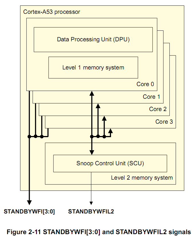
A53和系统电源管理控制器之间的通信有两种方式:分别是Core WFI、L2 WFI和Q-Channel。
STANDBYWFI[n]表示某个核处于idle和低功耗模式,电源管理控制器可以将此核的供电移除。
但是STANDBYWFIL2在所有核和L2都处于idle和低功耗模式才会触发。
Q-Channel是一个管理设备接口时钟和电源的控制器。
3 Programmers Model
3.1 About the programmers model
Exception levels:从EL0到EL3
指令集:AArch64执行态A64指令集,AArch32执行态T32和A32指令集。
还可能包含Advanced SIMD、FPU,Cryptography。
5 Memory Management Unit
5.1 About the MMU
TLB:Translation Lookaside Buffer
Cortex-A53支持两种架构AArch32(LPAE和Virtualization Extension两种地址转换)和AArch64(Long Descriptor Format地址转换)。
MMU将虚拟地址转换成物理地址,MMU提供一组虚拟地址转物理地址映射以及也表中内存属性来控制存储系统。
当地址被存取时,这些数据被加载到TLB中。
5.2 TLB organization
IPA:Intermediate Physical Address。
Micro TLB是转换表信息的第一层缓存,在每个指令或者数据侧都有一个。
Main TLB处理Micro TLB没命中的存取,它是512-entry、4-way、set-associative结构。
IPA cache RAM:保存IPA到Physical Address的映射。
5.3 TLB match process
每个TLB包含一个VA、block size、PA以及类似存储类型/存取权限的属性。
6 Level 1 Memory System
6.1 About the L1 memory system
L1包含独立的指令和数据cache,并且大小可以独立配置,8KB、16KB、32KB或64KB。
6.4 L1 Instruction memory system
L1指令cache负责提供指令流到DPU,为了提高性能和降低功耗,包括两个功能:
- 动态分支预测
- 指令缓存
程序流程预测主要包括三类:Predicted and non-predicted instructions、T32 state conditional branches、Return stack predictions。
6.5 L1 Data memory system
L1数据cache是物理寻址的cache,内部的TLB在访问cache之前就将虚拟地址转化成物理地址。
6.6 Data prefectching
7 Level 2 Memory System
7.1 About the L2 memory system
L2存储系统主要包括SCU(Snoop Control Unit)和L2 Cache。
SCU连接到Cluster中的四个核,SCU中同时保存了L1数据的备份。
L2存储系统通过AMBA 4 ACE或者AMBA 5 CHI总线和外部存储器连接,总线宽度128bit。
L2 cache大小有128KB、256KB、512KB、1MB。2MB。
7.2 Snoop Control Unit
SCP用户维护A53的核间L1数据一致性。
9 Generic Interrupt Controller CPU Interface
此部分只是关于GIC CPU Interface的概要介绍,GIC的实现细节有专门的技术参考手册介绍。
GIC CPU Interface与GIC接口,是CPU与GIC的桥梁。GIC CPU Interface和对应的GIC需要符合同样的规范,比如GICv2、GICv3、GICv4。
9.1 About the GIC CPU Interface
GIC CPU接口和外部中断分发器件集成提供了整个Cluster支持和管理中断的资源。
GIC CPU接口提供了管理中断源、中断行为、中断路由到一个或多个核的寄存器。
A53处理器GIC CPU接口实现了GICv4规范,并且和GICv3或GICv4中断分发器件接口。
GICv4架构提供如下功能:
•Two security states.
•Interrupt virtualization.
• Software-generated Interrupts (SGIs).
•Message Based Interrupts.
•System register access.
•Memory-mapped register access.
•Interrupt masking and prioritization.
•Cluster environments, including systems that contain more than eight cores.
•Wake-up events in power management environments.
在复位时将GICCDISABLE拉高,可以将GIC CPU接口关闭。
9.2 GIC programmers model
主要介绍GIC CPU接口相关寄存器,主要包括三部分:CPU Interface、Virtual Interface Control、Virtual CPU Interface。
每个CPU Interface模块在芯片内部提供A53和GIC分发器的接口。
Virtual Interface Control寄存器提供对A53处理器上软件配置,使其只被Hypervisor可见。
Virtual CPU Interface将虚拟中断转发到A53处理器,也遵守普通的GIC处理和优先级规则。
GIC相关阅读 - 《阅读GIC-500 Technical Reference Manual笔记》
10 Generic Timer
更详细的描述在ARMv8架构参考手册的G6: AArch32 System Register Descriptions
10.1 About the Generic Timer
Generic Timer根据计数递增值产生event和触发中断。
10.2 Generic Timer functional description
A53 cluster中每个核都有一系列timer相关寄存器:EL1 Non-secure physical timer、EL1 Secure physical timer、EL2 physical timer、Virtual Timer。
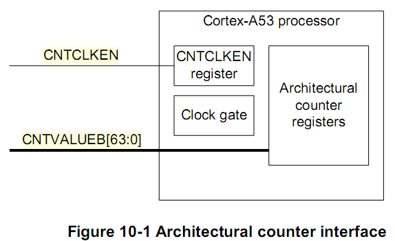
A53处理器内部并不包含system counter,system counter在SoC中。
A53处理器通过CNTVALUEB[63:0]来读取system counter的值,CNTCLKEN作为CNTVALUEB时钟的使能信号。
10.3 Generic Timer register summary
每个核内部都有一组Generic Timer寄存器,这些寄存器有根据32位和64位架构不同分为两类。
12 Performance Monitor Unit
A53的performance monitor版本是PMUv3,enable you to gather various statistics on the operation of the processor and its memory system during runtime。
PMU包括6个counters,每个counter可以对任何一种时间计数。
12.2 PMU functional description

Event interface从各种外部单元接收事件,Counters对各种事件进行计数。通过PMU register可以对PMU各种行为进行配置,对这些寄存器的配置可以通过APB接口等。
12.5 AArch32 PMU register summary
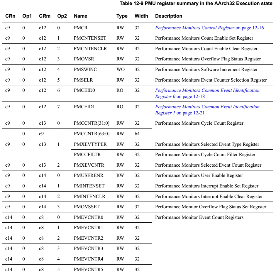
32位架构下可以通过MCR/MRC指令获取执行状态,64位对应MCRR/MRRC。
下面是PMU寄存器列表,更详细的描述在12.6 AArch32 PMU register descriptions。

12.9 Events
在对PMU基本架构和寄存器有了了解过后,再来看看都有哪些事件?
Table 12-28 PMU events给出了事件列表,主要包括L1 I、L1 D、L2 D、Exception、Branch、Bus等等。
这些事件只有在事件优化中实践一次,估计才能有具体感受。在此做个记录,知道PMU可以统计那些事件。
12.10 Interrupts
PMU产生中断然后通过触发nPMUIRQ输出。
12.11 Exporting PMU events
PMU事件有两个外部接口,一个是通过PMUEVENT,另一个是通过ETM trace。
通过Figure-14 Debug system components可以看出:
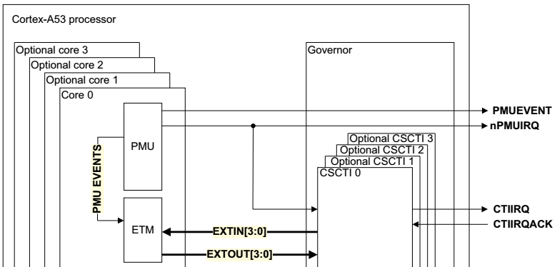
在PMU Events一节可以看出不同事件是否可以输出到PMUEVENT/Trace,以及其编号。
如何使用PMU进行性能调优呢?
- ARM官网《Performance Monitor Unit example code for ARM11 and Cortex-A/R》介绍了PMU使用步骤以及示例。
1.Disable performance counters
2.Set what each event counter will count
3.Set cycle counter tick rate
4.Reset performance counters
5.Enable performance counters
6.Call function to profile
7.Disable performance counters
8.Read out performance counters
9.Check that performance counters did not overflow
- 使用PMU进行cache命中率的测试《ARMv7 PMU(Performance Monitor Unit) 驱动(cache 命中率)》
- DS-5基于PMU进行调优