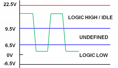
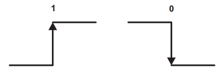
在双碳目标下,具有调光功能的LED驱动电源是重要的分支。DALI通信常用在LED的数字调光控制中,下文将通过C语言与单片机结合,解释DALI的原理及实现方法。
一、通信原理


1.6 从机回复指令结构
从机向主机回复包含1个起始位、8个数据位和两个停止位。

1.7 前向帧与后向帧时序约束
Te表示半个位的时间,即4.16.67uS;
两个前向帧时间间隔大于22个Te;
前向帧与后向帧之间时间间隔为7~22个Te;
后向帧与前向帧之间时间间隔大于22个Te;

1.8 主机与从机的握手
主机在发送指令后,在等候响应阶段,
如果收到从机发送的”0xFF“,就会认为从机接收成功;
如果在这个阶段处于空闲状态,就会认为从机没有接收成功;
二、实现方法
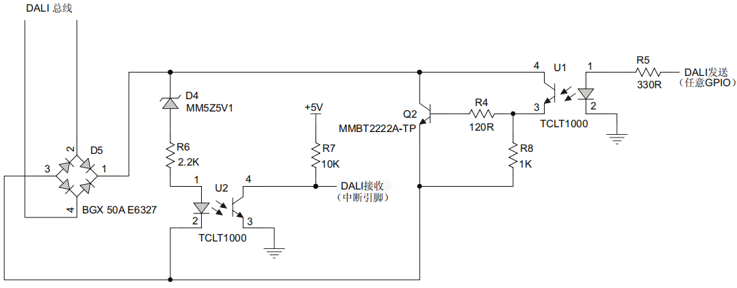
2.1 硬件原理图
下面的硬件主要是将DALI的电平信号,转为单片机能够接受的电平,下面那张是微芯公司DALI的参考通信电路。

2.1 从机接收思路及实现
本次从机的接收端,主要使用了一个边沿检测中断和一个定时器中断。

代码思路:
1)由于空闲状态,接收端的电平为高电平,产生起始信号时,需要从产生一个上升沿。于是,使用了外部下降沿触发中断,并关闭边沿触发中断;
2)检测到第一个下降沿后,定时器定时到0.75个周期,0.75个周期后读取第一位数据,并修改定时器周期为1个数据位时长。
3)第二次定时结束时读取第二位数据,依次读取后面的数据
4)当读到最后一位数据的时候,也就是LSB后的两位时,停止定时器,并初始化定时器为0.75个数据周期,然后开启边沿触发中断。
C语言程序:
  1 //配置边沿触发及中断
  2 void IO_Change_Init(void){
  3
  4     //Set the CN2 as the IO state change flag
  5     CNEN1bits.CN2IE=1;//Open the IO state interrupt
  6     CNPU1bits.CN2PUE=0;//Disable the weak up
  7
  8     IFS1bits.CNIF=0;//Clear the interrupt flag
  9     IPC4bits.CNIP=7;//Configure the interrupt level 7
 10     IEC1bits.CNIE=1;//Enable this interrupt
 11 }
 12 //检测到第一个下降沿
 13 void __attribute__ ((__interrupt__,__no_auto_psv__)) _CNInterrupt(void){
 14
 15    IFS1bits.CNIF = 0; //Clear the interrupt flag
 16
 17    //Disable the IO State Interrupt and start the Time
 18    T1CONbits.TON = 1;
 19    CNEN1bits.CN2IE = 0;
 20
 21 }
 22 //配置定时器初使周期为0.75个数据位时长
 23 void Tim1_Init(void){
 24     T1CON = 0x0020;
 25
 26     IEC0bits.T1IE = 1;
 27     IPC0bits.T1IP = 7;
 28     IFS0bits.T1IF = 0;
 29
 30     TMR1 = 0;
 31     PR1 = 390;
 32     T1CONbits.TON = 0;
 33 }
 34 //在定时器中断里面读取数据
 35 void __attribute__((__interrupt__,auto_psv,__shadow__)) _T1Interrupt(void)
 36 {
 37     IFS0bits.T1IF = 0;
 38
 39     if(LLC_DALI_Rx_Mode == 1)
 40     {
 41         switch(Timer_Num)
 42         {
 43             case 0:
 44                 Timer_Num++;
 45                 T1CONbits.TON = 0; //关闭定时器
 46                 PR1 = 520; //设置下一个定时时长为1个周期
 47                 TMR1 = 0;//初使化定时器初始值
 48                 T1CONbits.TON = 1;//开启定时器
 49                 break;
 50             case 1:
 51                 if(_RB0 == 1 )Address_temp |= (1<<7);
 52                 Timer_Num++;
 53                 break;
 54             case 2:
 55                 if(_RB0 == 1 )Address_temp |= (1<<6);
 56                 Timer_Num++;
 57                 break;
 58             case 3:
 59                 if(_RB0 == 1 )Address_temp |= (1<<5);
 60                 Timer_Num++;
 61                 break;
 62             case 4:
 63                 if(_RB0 == 1 )Address_temp |= (1<<4);
 64                 Timer_Num++;
 65                 break;
 66             case 5:
 67                 if(_RB0 == 1 )Address_temp |= (1<<3);
 68                 Timer_Num++;
 69                 break;
 70             case 6:
 71                 if(_RB0 == 1 )Address_temp |= (1<<2);
 72                 Timer_Num++;
 73                 break;
 74             case 7:
 75                 if(_RB0 == 1 )Address_temp |= (1<<1);
 76                 Timer_Num++;
 77                 break;
 78             case 8:
 79                 if(_RB0 == 1 )Address_temp |= (1<<0);
 80                 Timer_Num++;
 81                 break;
 82             case 9:
 83                 if(_RB0 == 1 )Command_temp |= (1<<7);
 84                 Timer_Num++;
 85                 break;
 86             case 10:
 87                 if(_RB0 == 1 )Command_temp |= (1<<6);
 88                 Timer_Num++;
 89                 break;
 90             case 11:
 91                 if(_RB0 == 1 )Command_temp |= (1<<5);
 92                 Timer_Num++;
 93                 break;
 94             case 12:
 95                 if(_RB0 == 1 )Command_temp |= (1<<4);
 96                 Timer_Num++;
 97                 break;
 98             case 13:
 99                 if(_RB0 == 1 )Command_temp |= (1<<3);
100                 Timer_Num++;
101                 break;
102             case 14:
103                 if(_RB0 == 1 )Command_temp |= (1<<2);
104                 Timer_Num++;
105                 break;
106             case 15:
107                 if(_RB0 == 1 )Command_temp |= (1<<1);
108                 Timer_Num++;
109                 break;
110             case 16:
111                 if(_RB0 == 1 )Command_temp |= (1<<0);
112                 Timer_Num++;
113                 break;
114             case 17:
115                 if(_RB0 == 1 )StopBit_temp |= (1<<1);
116                 Timer_Num++;
117                 break;
118             case 18:
119                 if(_RB0 == 1 )StopBit_temp |= (1<<0);
120                 Timer_Num++;
121                 break;
122             case 19:
123                    T1CONbits.TON = 0;//关闭定时器
124                    PR1 = 390;//设置下一个定时器周期为0.75个数据位时长
125                    TMR1 = 0;//定时器计数初始值置0
126                    CNEN1bits.CN2IE = 1;//开启边沿检测中断
127                    //数据获取,这里还可以添加数据包检验程序
128                    Command = Command_temp;
129                    Address = Address_temp;
130                    StopBit = StopBit_temp;
131
132                    Command_temp = 0;
133                    Address_temp = 0;
134                    StopBit_temp = 0;
135                    Timer_Num = 0;
136                 break;
137         }
138     }
139
140
141
2.2 从机思路及实现
从机的回复相对较简单,只需要在每半个数据位修改输出引脚的电平。分别发送1个起始位、8个数据位和两个停止位。
代码思路:
1)接收数据完成并定时等待8Te
2)发送一个引脚低电平,并设置下一个定时周期为Te,定时器初使值为0,并开启定时器;
3)在后面的定时器中断里面,发送起始位;
4)在后面的定时器中断里面,发送数据位;
5)在后面的定时器中断里面,发送停止位;
6)初使化发送数据计数变量,初始化定时器计数值为零,关闭定时器;
7)开启边沿触发中断;
C语言程序实现
 1   if(LLC_DALI_Tx_Mode == 1){
 2         switch(Timer_Num)
 3         {
 4             case 0:
 5                 //Send the Start Bit
 6                 _RF3 = 0;
 7                 T1CONbits.TON = 0;
 8                 PR1 = 260;
 9                 TMR1 = 0;
10                 T1CONbits.TON = 1;
11                 Timer_Num++;
12                 break;
13             case 1:
14                 _RF3 = 1;
15                 Timer_Num++;
16                 break;
17             case 2:
18                  //Send the Data Bits
19                 _RF3 = ((Transfer_Data & 0x80)>0)?0:1;
20                 Timer_Num++;
21                 break;
22             case 3:
23                 _RF3 = ((Transfer_Data & 0x80)>0)?1:0;
24                 Timer_Num++;
25                 break;
26             case 4:
27                  _RF3 = ((Transfer_Data & 0x40)>0)?0:1;
28                 Timer_Num++;
29                 break;
30             case 5:
31                 _RF3 = ((Transfer_Data & 0x40)>0)?1:0;
32                 Timer_Num++;
33                 break;
34             case 6:
35                 _RF3 = ((Transfer_Data & 0x20)>0)?0:1;
36                 Timer_Num++;
37                 break;
38             case 7:
39                 _RF3 = ((Transfer_Data & 0x20)>0)?1:0;
40                 Timer_Num++;
41                 break;
42             case 8:
43                 _RF3 = ((Transfer_Data & 0x10)>0)?0:1;
44                 Timer_Num++;
45                 break;
46             case 9:
47                 _RF3 = ((Transfer_Data & 0x10)>0)?1:0;
48                 Timer_Num++;
49                 break;
50             case 10:
51                 _RF3 = ((Transfer_Data & 0x08)>0)?0:1;
52                 Timer_Num++;
53                 break;
54             case 11:
55                 _RF3 = ((Transfer_Data & 0x08)>0)?1:0;
56                 Timer_Num++;
57                 break;
58             case 12:
59                 _RF3 = ((Transfer_Data & 0x04)>0)?0:1;
60                 Timer_Num++;
61                 break;
62             case 13:
63                 _RF3 = ((Transfer_Data & 0x04)>0)?1:0;
64                 Timer_Num++;
65                 break;
66             case 14:
67                 _RF3 = ((Transfer_Data & 0x02)>0)?0:1;
68                 Timer_Num++;
69                 break;
70             case 15:
71                 _RF3 = ((Transfer_Data & 0x02)>0)?1:0;
72                 Timer_Num++;
73                 break;
74             case 16:
75                 _RF3 = ((Transfer_Data & 0x01)>0)?0:1;
76                 Timer_Num++;
77                 break;
78             case 17:
79                 _RF3 = ((Transfer_Data & 0x01)>0)?1:0;
80                 Timer_Num++;
81                 break;
82             case 18:
83                 //Send the stop bit;
84                 T1CONbits.TON = 0;
85                 TMR1 = 0;
86                 PR1 = 260<<2;
87                 T1CONbits.TON = 1;
88                 _RF3 = 1;
89                 Timer_Num++;
90                 break;
91             case 19:
92                    T1CONbits.TON = 0;  //关闭定时器
93                    CNEN1bits.CN2IE = 1;//开启边沿检测中断
94                    TMR1 = 0;  //定时器初始值置0
95                    PR1 = 260; //定时器周期设置为Te
96                    Timer_Num = 0;//初使定时器数据位计数
97                 break;
98         }
99     }
三、测试结果
3.1 从机发送测试
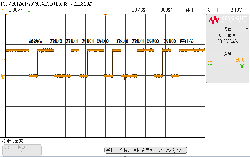
从机发送数据100,对应二进制为0b0110 0100,实际发送波形见下图:

实际发送数据为0b01100100,发送正常。
3.2 主机发送从机识别测试
主机通过上位机发送调光指令为239,从机在线调试识别出来的数据为239。接收正常。


四、小结
从机的接收程序,定时器的定时步长先是1.5个Te,然后是2个Te;
从机的发送程序,定时器的定时步长为1个Te;
从机的接收程序,边沿触发只触发依次就关闭了。
从机的发送程序,发送完毕开启边沿触发。
在定时器中断里面,修改下一个定时时长,理论上可以做到每一个定时周期都不一样,这思维可以用于实现更加复杂的功能。
注意:
1)以上代码发送和接收是独立的,没有遵循通信的时序。1.7节里面有具体时序要求,根据时序稍做修改就可以啦。
2)本次代码,没有考虑到时序有10%的误差。有待改善。
五、参考资料
【1】Digital Addressable Lighting Interface (DALI) Control Devices Protocol,PART 1-2004
【2】DALI控制装置,AN1487,Microchip
【3】数字可寻址照明接口(DALI)通信,AN1465,Microchip
【4】Digital Addressable Lighting Interface (DALI) Implementation Using MSP430 Value Line Microcontrollers,TI