netns 可以创建一个完全隔离的新网络环境,这个环境包括一个独立的网卡空间,路由表,ARP表,ip地址表,iptables等。总之,与网络有关的组件都是独立的。
创建网络空间:
# ip netns add ns1
查看网络空间:
# ip netns list
删除网络空间:
# ip netns del ns1
进入网络空间执行命令:
# ip netns exec ns1 `command`
实例一:
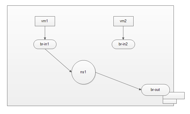
用netns连接两个隔离环境中的虚拟机,如图:
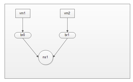
在虚拟化中有两个虚拟机网络隔离环境需要通信。
系统: centos7.2 x64
安装程序包
# yum install bridge-utils libvirt libvirt-client virt-install virt-viewer net-tools -y

# brctl addbr br0
# brctl addbr br1
# ifconfig br0 up
# ifconfig br1 up
取消默认nat网络模式
# mv /etc/libvirt/qemu/networks/default.xml /etc/libvirt/qemu/networks/default.xml_bak
# systemctl start libvirtd
创建虚拟机并连接至br0
# virt-install --name vm1 --ram 512 --vcpus=1 --disk /images/linux/cirros-0.3.5-i386-disk-1.img --network bridge=br0,model=virtio --force --import --nographics --serial=pty --console=pty

打开第二个终端创建第二个虚拟机并连接至br1

# virt-install --name vm2 --ram 512 --vcpus=1 --disk /images/linux/cirros-0.3.5-i386-disk-2.img --network bridge=br1,model=virtio --force --import --nographics --serial=pty --console=pty

# brctl show
bridge name    bridge id        STP enabled    interfaces
br0        8000.fe54007e1861    no        vnet0
br1        8000.fe5400be1885    no        vnet1
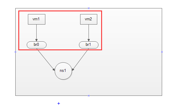
到此,虚拟机已经连接上各自的桥设备了。完成如图:
创建虚拟网络空间:

# ip netns add ns1
# ip netns list
ns1
接下来创建一张虚拟网卡,虚拟网卡分为前半段和后半段,我们将前半段添加到br0中,并将后半段添加到虚拟网络空间中,这样br0桥设备中主机就能够连接到虚拟网络空间中。
# ip link add net-in type veth peer name net-out
# ifconfig net-in up
# ifconfig net-out up
将net-in虚拟网卡添加到br0中,将net-out虚拟网卡添加到ns1中
# brctl addif br0 net-in

查看是否添加成功
# brctl show br0
bridge name    bridge id        STP enabled    interfaces
br0        8000.46c7e9d2c0fa    no            net-in
                                        vnet0
将net-out添加到ns1中,并重命名为eth0
# ip link set dev net-out name eth0 netns ns1
查看是否添加成功
# ip netns exec ns1 ifconfig -a
eth0: flags=4098<BROADCAST,MULTICAST>  mtu 1500
        ether a2:07:dc:ba:35:a2  txqueuelen 1000  (Ethernet)
        RX packets 0  bytes 0 (0.0 B)
        RX errors 0  dropped 0  overruns 0  frame 0
        TX packets 0  bytes 0 (0.0 B)
        TX errors 0  dropped 0 overruns 0  carrier 0  collisions 0

lo: flags=8<LOOPBACK>  mtu 65536
        loop  txqueuelen 0  (Local Loopback)
        RX packets 0  bytes 0 (0.0 B)
        RX errors 0  dropped 0  overruns 0  frame 0
        TX packets 0  bytes 0 (0.0 B)
        TX errors 0  dropped 0 overruns 0  carrier 0  collisions 0


# ip netns exec ns1 ifconfig lo up
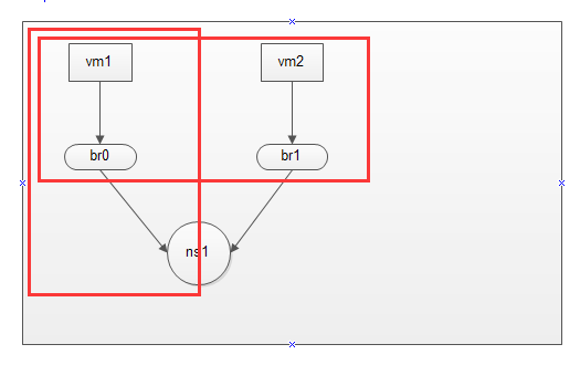
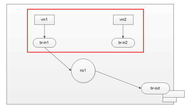
现在vm1 --> br0 --> ns1 网络做通了,完成如下图:
同理,和上面操作一样。
# ip link add net1-in type veth peer name net1-out
# ifconfig net1-in up
# ifconfig net1-out up

# brctl addif br1 net1-in

# brctl show br1
bridge name    bridge id        STP enabled    interfaces
br1        8000.1291a963b290    no        net1-in
                            vnet1

# ip link set dev net1-out name eth1 netns ns1


# ip netns exec ns1 ifconfig -a
eth0: flags=4098<BROADCAST,MULTICAST>  mtu 1500
        ether a2:07:dc:ba:35:a2  txqueuelen 1000  (Ethernet)
        RX packets 0  bytes 0 (0.0 B)
        RX errors 0  dropped 0  overruns 0  frame 0
        TX packets 0  bytes 0 (0.0 B)
        TX errors 0  dropped 0 overruns 0  carrier 0  collisions 0

eth1: flags=4098<BROADCAST,MULTICAST>  mtu 1500
        ether 02:d4:3c:7d:3b:2e  txqueuelen 1000  (Ethernet)
        RX packets 0  bytes 0 (0.0 B)
        RX errors 0  dropped 0  overruns 0  frame 0
        TX packets 0  bytes 0 (0.0 B)
        TX errors 0  dropped 0 overruns 0  carrier 0  collisions 0

lo: flags=73<UP,LOOPBACK,RUNNING>  mtu 65536
        inet 127.0.0.1  netmask 255.0.0.0
        inet6 ::1  prefixlen 128  scopeid 0x10<host>
        loop  txqueuelen 0  (Local Loopback)
        RX packets 0  bytes 0 (0.0 B)
        RX errors 0  dropped 0  overruns 0  frame 0
        TX packets 0  bytes 0 (0.0 B)
        TX errors 0  dropped 0 overruns 0  carrier 0  collisions 0
ip地址配置如下:
vm1 - eth0 : 192.168.1.2
ns1 - eth0 : 192.168.1.1
vm2 - eth0 : 172.168.10.2
ns1 - eth0 : 172.168.10.1
记住:当宿主机开启了网络转发功能,虚拟网络空间才会开启,在以上场景中,必须开启网络转发功能。
# sysctl -w net.ipv4.ip_forward=1
net.ipv4.ip_forward = 1
vm1 - eth0 网络配置如下:
# ifconfig lo up
# ifconfig eth0 192.168.1.2/24 up
# ifconfig
eth0      Link encap:Ethernet  HWaddr 52:54:00:7E:18:61
          inet addr:192.168.1.2  Bcast:192.168.1.255  Mask:255.255.255.0
          inet6 addr: fe80::5054:ff:fe7e:1861/64 Scope:Link
          UP BROADCAST RUNNING MULTICAST  MTU:1500  Metric:1
          RX packets:8 errors:0 dropped:0 overruns:0 frame:0
          TX packets:2 errors:0 dropped:0 overruns:0 carrier:0
          collisions:0 txqueuelen:1000
          RX bytes:648 (648.0 B)  TX bytes:168 (168.0 B)

lo        Link encap:Local Loopback
          inet addr:127.0.0.1  Mask:255.0.0.0
          inet6 addr: ::1/128 Scope:Host
          UP LOOPBACK RUNNING  MTU:16436  Metric:1
          RX packets:0 errors:0 dropped:0 overruns:0 frame:0
          TX packets:0 errors:0 dropped:0 overruns:0 carrier:0
          collisions:0 txqueuelen:0
          RX bytes:0 (0.0 B)  TX bytes:0 (0.0 B)
ns1 - eth0 网络配置如下:
# ip netns exec ns1 ifconfig lo up
# ip netns exec ns1 ifconfig eth0 192.168.1.1/24 up
# ip netns exec ns1 ifconfig eth0
eth0: flags=4099<UP,BROADCAST,MULTICAST>  mtu 1500
        inet 192.168.1.1  netmask 255.255.255.0  broadcast 192.168.1.255
        ether a2:07:dc:ba:35:a2  txqueuelen 1000  (Ethernet)
        RX packets 0  bytes 0 (0.0 B)
        RX errors 0  dropped 0  overruns 0  frame 0
        TX packets 0  bytes 0 (0.0 B)
        TX errors 0  dropped 0 overruns 0  carrier 0  collisions 0
vm2 - eth0 网络配置如下:
# ifconfig lo up
# ifconfig eth0 172.168.10.2/24 up
# ifconfig eth0
eth0      Link encap:Ethernet  HWaddr 52:54:00:BE:18:85
          inet addr:172.168.10.2  Bcast:172.168.255.255  Mask:255.255.0.0
          inet6 addr: fe80::5054:ff:febe:1885/64 Scope:Link
          UP BROADCAST RUNNING MULTICAST  MTU:1500  Metric:1
          RX packets:8 errors:0 dropped:0 overruns:0 frame:0
          TX packets:2 errors:0 dropped:0 overruns:0 carrier:0
          collisions:0 txqueuelen:1000
          RX bytes:648 (648.0 B)  TX bytes:168 (168.0 B)
ns1 - eth1 网络配置如下:
# ip netns exec ns1 ifconfig eth1 172.168.10.1/24 up
# ip netns exec ns1 ifconfig eth1
eth1: flags=4099<UP,BROADCAST,MULTICAST>  mtu 1500
        inet 172.168.10.1  netmask 255.255.255.0  broadcast 172.168.10.255
        ether 02:d4:3c:7d:3b:2e  txqueuelen 1000  (Ethernet)
        RX packets 0  bytes 0 (0.0 B)
        RX errors 0  dropped 0  overruns 0  frame 0
        TX packets 0  bytes 0 (0.0 B)
        TX errors 0  dropped 0 overruns 0  carrier 0  collisions 0
为虚拟机指定路由:
vm1 :
# ping 192.168.1.1 -c1
PING 192.168.1.1 (192.168.1.1): 56 data bytes
64 bytes from 192.168.1.1: seq=0 ttl=64 time=0.811 ms

--- 192.168.1.1 ping statistics ---
1 packets transmitted, 1 packets received, 0% packet loss
round-trip min/avg/max = 0.811/0.811/0.811 ms


# ip route add default via 192.168.1.1
注意:如果ping不通,请检查链路上的网卡状态是否是up状态。
vm2 :
# ping  172.168.10.1 -c1
PING 172.168.10.1 (172.168.10.1): 56 data bytes
64 bytes from 172.168.10.1: seq=0 ttl=64 time=2.385 ms

--- 172.168.10.1 ping statistics ---
1 packets transmitted, 1 packets received, 0% packet loss
round-trip min/avg/max = 2.385/2.385/2.385 ms

添加默认路由

# ip route add default via 172.168.10.1
接下来,使用ping测试。
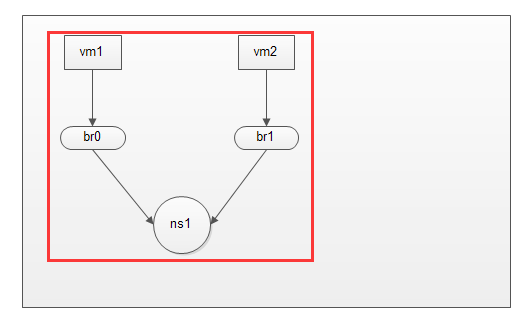
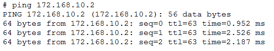
vm1 - eth0 : 192.168.1.2  --> ns1 - eth1 : 172.168.10.1

# ping 172.168.10.1 -c1
PING 172.168.10.1 (172.168.10.1): 56 data bytes
64 bytes from 172.168.10.1: seq=0 ttl=64 time=0.426 ms

--- 172.168.10.1 ping statistics ---
1 packets transmitted, 1 packets received, 0% packet loss
round-trip min/avg/max = 0.426/0.426/0.426 ms

能够达到ns1 eth1网卡,说明ns1从eth0 - 192.168.10.1 转发到了 172.168.10.1


vm1 - eth0 : 192.168.1.2  --> vm2 - eth0 : 172.168.10.2
这样,就完成了在宿主机中,两个虚拟主机隔离模式的通信。
实例二:
说明:宿主机中两组隔离模型,其中只有一组可以访问公网
接下来,在模式一的基础上进行修改:
# ip netns del ns1
删除虚拟网络空间模式,所有和虚拟网络空间有关的虚拟网卡都会被删除。
现在的模式如下:
vm1: 192.168.1.2/24
vm2: 192.168.1.2/24
ns1: 192.168.1.1/24
这里故意把vm1和vm2的ip设置为一样,方便我们进行测试。
添加虚拟网络空间
# ip netns add ns1
# ip link add net-in type veth peer name net-out
# ifconfig net-in up
# ifconfig net-out up
添加net-in到br0,添加net-out到虚拟网络空间ns1

# brctl addif br0 net-in
# ip link set dev net-out name eth0 netns ns1

为ns1启动网卡并配置ip地址

# ip netns exec ns1 ifconfig lo up
# ip netns exec ns1 ifconfig eth0 192.168.1.1 netmask 255.255.255.0 up
为vm1配置网关为192.168.1.1
创建桥设备,并将物理网卡添加到桥设备中,这里建议直接修改物理网卡配置文件
cp -a ifcfg-eno16777736 ifcfg-br-out

# vim ifcfg-eno16777736

TYPE=Ethernet
BOOTPROTO=none
DEFROUTE=yes
PEERDNS=yes
PEERROUTES=yes
IPV4_FAILURE_FATAL=no
IPV6INIT=no
NAME=eno16777736
UUID=100e462e-c0d0-4271-9b5a-1c8e47ff0d03
DEVICE=eno16777736
ONBOOT=yes
BRIDGE=br-out

# vim ifcfg-br-out

TYPE=Bridge
BOOTPROTO=none
DEFROUTE=yes
PEERDNS=yes
PEERROUTES=yes
IPV4_FAILURE_FATAL=no
IPV6INIT=no
NAME=br-out
DEVICE=br-out
ONBOOT=yes
IPADDR=10.0.0.11
NETMASK=255.255.255.0
GATEWAY=10.0.0.1
DNS1=10.0.0.1
DNS2=114.114.114.114

重启下网络
# systemctl restart network

物理网卡添加成功
# brctl show br-out
bridge name    bridge id        STP enabled    interfaces
br-out        8000.000c2923e15d    no        eno16777736
现在创建一对网卡,连接ns1和br-out
# ip link add net1-in type veth peer name net1-out
# ifconfig net1-in up
# ifconfig net1-out up

# ip link set dev net1-in name eth1 netns ns1
# brctl addif br-out net1-out
# brctl show br-out
bridge name    bridge id        STP enabled    interfaces
br-out        8000.000c2923e15d    no        eno16777736
                                        net1-out
我真实局域网的ip为10.0.0.0/24
因此添加到ns1中的eth1要配置到同网段
# ip netns exec ns1 ifconfig eth1 10.0.0.12 netmask 255.255.255.0 up
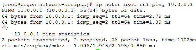
能够到达网关了。
已实现如下:
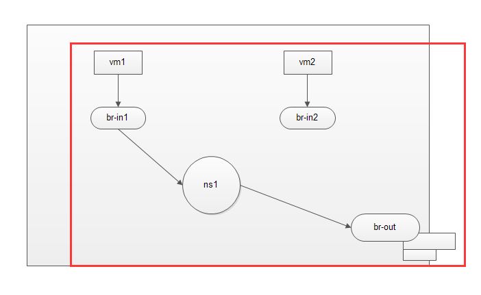
在ns1中添加源地址转换
# ip netns exec ns1 iptables -t nat -A POSTROUTING -s 192.168.1.0/24 ! -d 192.168.1.0/24 -j SNAT --to-source 10.0.0.12
# ip netns exec ns1 ip route default via 10.0.0.1
再次通过vm1 ping 公网ip
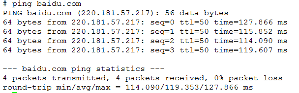
这样就实现了宿主机内部分网络中的主机可以访问公网,部分主机没有访问公网权限。
总之,网络逻辑很重要。