序言
这个是我在做FPGA界的HelloWorld——数字钟设计时随手写下的,再现了数字钟设计的过程
目标分析
- 时钟具有时分秒的显示,需6个数码管。为了减小功耗采用扫描法显示
- 按键设置时间,需要对按键进行消抖
- 时分秒即为2个60进制计数器,一个24进制计数器。

模块设计
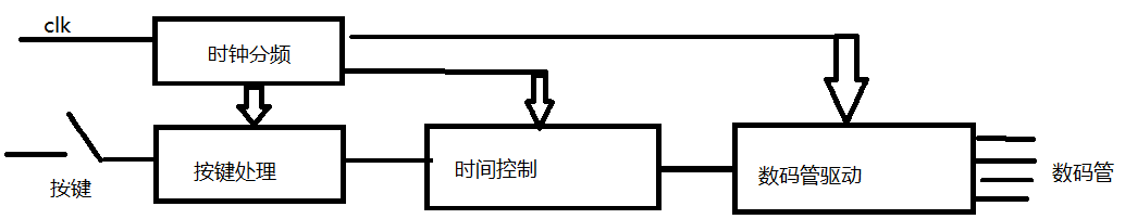
综上所述,我采用模块化设计方法进行设计,绘制框图如下。
- 时钟分频产生各个模块所需频率时钟。
- 按键处理模块对按键信号进行消抖、变长脉冲为短脉冲等处理。
- 时间控制模块产生时间信号或对时间进行设置。
- 数码管驱动模块负责对时间信号BCD码译码为数码管的段码并且扫描输出到数码管。
下面对各个模块分别详细叙述
时钟分频模块
我打算把时钟分频模块做成“数控N分频器”,通过给分频器传入数值N来对时钟信号进行N分频。得到的信号频率为原时钟信号的频率/N,占空比为1/N。
稍微考虑下其他模块所需时钟:按键处理模块100Hz ,时间控制模块1Hz,数码管驱动50Hz。而输入时钟为33.8688MHz。
我不想传入的N数值过大,我打算先对时钟进行两次:第一次调用时钟分频模块得到1Mhz,第二次得到1Khz。这样N的位数为10可以满足需求。
代码如下
library IEEE;
use IEEE.STD_LOGIC_1164.all;
use IEEE.STD_LOGIC_UNSIGNED.all;

entity ClkDiv is
	port(
	clk_i:IN STD_LOGIC;
	N_i:  IN STD_LOGIC_VECTOR(9 DOWNTO 0);
	clk_o:OUT STD_LOGIC);
end ClkDiv;

architecture behavior of ClkDiv is
signal count:STD_LOGIC_VECTOR(9 DOWNTO 0):="0000000001";
signal clk_temp:STD_LOGIC:='0';
begin
	process(clk_i)
	begin
		if(clk_i'EVENT and clk_i='1')then
			if (count=N_i)then
				count<="0000000001";
				clk_temp<='1';
			else
				count<=count+1;
				clk_temp<='0';
			end if;
		end if;
	end process;
	clk_o<=clk_temp;
end behavior;
仿真结果如下:
2分频:输出信号为f/2Hz,占空比1:2

3分频:输出信号为f/3Hz,占空比1:3

按键处理模块
去抖动根据以往的经验,按键按下弹起电平会有一小段毛刺,可能会引起电路误操作,所以要对按键进行消抖处理使变为干净的矩形信号。
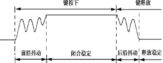
抖动时间一般为10ms,若采样时间为10ms则噪声最多采样到一次。
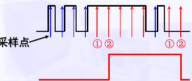
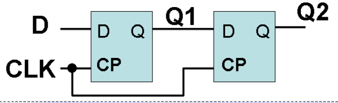
对于两级D触发器,Q1和Q2之间有一个时间延迟效果。每一次时钟上升沿就是对信号采样一次,Q1保存的是最新一次的采样,Q2保存的是上一次的采样,Q1和Q2之间有一个时间延迟,时间为时钟周期。
对于噪声信号只能采样到一次,Q1*Q2的值一定为0。
对于持续时间大于时钟周期的信号可以采样到两次,Q1的值和Q2的值相同,Q1*Q2为信号电平。这就是去抖原理。
代码如下
library IEEE;
use IEEE.STD_LOGIC_1164.all;
use IEEE.STD_LOGIC_UNSIGNED.all;

entity JitterElimination is
	port(
	key: IN STD_LOGIC;
	clk_i:IN STD_LOGIC;
	DLY_OUT:OUT STD_LOGIC);

end JitterElimination;

architecture rtl of JitterElimination is
signal D1,D2,S:STD_LOGIC;
begin
	process(clk_i)
	begin
		if (clk_i'EVENT and clk_i='1')then
			D1<=key;
			D2<=D1;
		end if;
	end process;
	S<=D1 and D2;
	DLY_OUT<=S;

end rtl;
仿真结果如下

可以看到,按键的抖动被消除了,但是可以看到按键按下电平持续时间跨过几个时钟周期。如果有必要可以使用微分电路把矩形波转换为窄脉冲波,这里不需要。
数码管驱动模块
时分秒显示需要2+2+2=6个数码管,每个数码管的显示需要8根引脚。使用扫描方式显示,只需要6+8=14根引脚,功耗比较低。
输入:时间信号BCD码有4*6=24位,用于控制扫描频率的时钟信号是1个输入信号
输出:位选信号6位,段码8位
library IEEE;
use IEEE.STD_LOGIC_1164.all;

entity LEDScan is
	port(
		CurTime_i:  IN STD_LOGIC_VECTOR(23 DOWNTO 0);
		clk_i:IN STD_LOGIC;
		Position_o:OUT STD_LOGIC_VECTOR(5 DOWNTO 0);
		Section_o: OUT STD_LOGIC_VECTOR(7 DOWNTO 0));
	function convert(BCD:STD_LOGIC_VECTOR(3 DOWNTO 0)) return STD_LOGIC_VECTOR is
		variable Section: STD_LOGIC_VECTOR(7 DOWNTO 0);
	begin
		Case BCD is
			when "0000" =>Section:="00111111"; --段码表————————————---------------------------------------------
			when "0001" =>Section:="00000110"; --0x3f,0x06,0x5b,0x4f,0x66,
			when "0010" =>Section:="01011011"; --0x6d,0x7d,0x07,0x7f,0x6f,0x77,0x7c,0x39,0x5e,0x79,0x71
			when "0011" =>Section:="01001111";
			when "0100" =>Section:="01100110";

			when "0101" =>Section:="01101101";
			when "0110" =>Section:="01111101";
			when "0111" =>Section:="00000111";
			when "1000" =>Section:="01111111";
			when "1001"	=>Section:="01101111";
			when OTHERS =>Section:="01100110";--01110001

--			when "0000" =>Section:="11000000"; --段码表{0x88,0x83,0xc6,0xa1,0x86,0x8e}----------------
--			when "0001" =>Section:="11111001"; --0xc0,0xf9,0xa4,0xb0,0x99,
--			when "0010" =>Section:="10100100"; --0x92,0x82,0xf8, 0x80,0x90,
--			when "0011" =>Section:="10110000";
--			when "0100" =>Section:="10011001";
--
--			when "0101" =>Section:="10010010";
--			when "0110" =>Section:="10000010";
--			when "0111" =>Section:="11111000";
--			when "1000" =>Section:="10000000";
--			when "1001"	=>Section:="10010000";
--			when OTHERS =>Section:="10001110";
		end case;
		return Section;
	end convert;
end LEDScan;


architecture behaviour of LEDScan is
	signal CurTimeTemp:STD_LOGIC_VECTOR(23 DOWNTO 0):="000000000000000000000000";
	signal SectionTemp,Section0,Section1,Section2,Section3,Section4,Section5:  STD_LOGIC_VECTOR(7 DOWNTO 0):="00111111";--此处应为0的段码,数码管共阴数码管-----------------------------------------------------------------------
	signal Position	:integer :=5;
begin

	process(clk_i)
	begin
		if (clk_i'EVENT and clk_i='1') then

			CurTimeTemp<=CurTime_i;
			Section0<=convert(CurTimeTemp(3 DOWNTO 0));
			Section1<=convert(CurTimeTemp(7 DOWNTO 4));
			Section2<=convert(CurTimeTemp(11 DOWNTO 8));
			Section3<=convert(CurTimeTemp(15 DOWNTO 12));
			Section4<=convert(CurTimeTemp(19 DOWNTO 16));
			Section5<=convert(CurTimeTemp(23 DOWNTO 20));

			if (Position=5)then
				Position<=0;
			else
				Position<=Position+1;
			end if;

			case Position is
				when 0 =>Section_o<=Section0;Position_o<="000001";
				when 1 =>Section_o<=Section1;Position_o<="000010";
				when 2 =>Section_o<='1'&Section2(6 downto 0);Position_o<="000100"; --添加小数点
				when 3 =>Section_o<=Section3;Position_o<="001000";
				when 4 =>Section_o<='1'&Section4(6 downto 0);Position_o<="010000";
				when 5 =>Section_o<=Section5;Position_o<="100000";
				when OTHERS=>NULL;
			end case;
		end if;
	end process;


end behaviour;
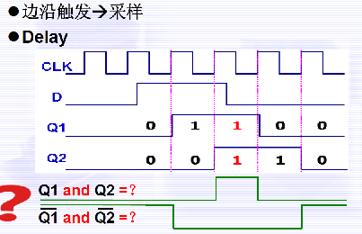
仿真结果如下图所示
我们可以看到在当前时间为23:59:59的情况下Section5里面放的是2的段码,Section4里面放的是3的段码,Section3里面放的是5的段码
在时钟的作用下,Position_o依次选中个位,Section_o输出的是选中位置的段码。
时间控制模块
我想用两个按键分别设置分钟,时钟数值。分钟增1的条件是按键按下或者秒计数器进位,时钟增1的条件是按键2按下或者分钟计数器进位。这样可以在不破坏正常运行状态的情况下,用按键对分、时进行加1操作(设置),满足了功能又没有增加设计的复杂度。
最后将计数器的值翻译为BCD码,连接到一起形成24位BCD码。
输入:按键1和按键2、1Hz时间脉冲
输出:24位BCD码
N进制计数器
library IEEE;
use ieee.std_logic_1164.all;
use ieee.std_logic_arith.all;
use ieee.std_logic_unsigned.all;
use ieee.numeric_std.all;

entity Counter is
	port(
	CountClk:in STD_LOGIC;
	N: in STD_LOGIC_VECTOR(4 downto 0);
	count:out STD_LOGIC_VECTOR(4 downto 0);
	Cout:out STD_LOGIC);
end Counter;


architecture behav of Counter is
signal count_temp: STD_LOGIC_VECTOR(4 downto 0):="00000";
signal CoutTemp:STD_LOGIC:='0';
begin
	process(CountClk)
	begin
		if (CountClk'EVENT and CountClk='1')then
			count_temp<=count_temp+1;
			CoutTemp<='0';
			if (count_temp>=N)then
				count_temp<="00000";
				CoutTemp<='1';
			end if;
		end if;
	end process;
	Cout<=CoutTemp;
	count<=count_temp;
end behav;
控制模块
library IEEE;
use ieee.std_logic_1164.all;
use ieee.std_logic_arith.all;
use ieee.std_logic_unsigned.all;
use ieee.numeric_std.all;


entity Contrl is
		port(
			MinKey_i:IN STD_LOGIC;
			HourKey_i:IN STD_LOGIC;
			clk_i:IN STD_LOGIC;
			CurrentTimeBCD_o: OUT STD_LOGIC_VECTOR(23 downto 0));
end Contrl;

architecture behavior of Contrl is
	signal h: integer range 0 to 23 := 0;	-- 秒钟个位
	signal m: integer range 0 to 59 := 0;	-- 秒钟个位
	signal s: integer range 0 to 59 := 0;	-- 秒钟个位
	signal s1: integer range 0 to 9 := 0;	-- 秒钟个位
	signal s2: integer range 0 to 5 := 0;	-- 秒钟百位
	signal m1: integer range 0 to 9 := 0;	-- 分钟个位
	signal m2: integer range 0 to 5 := 0;	-- 分钟百位
	signal h1: integer range 0 to 9 := 0;	-- 时钟个位
	signal h2: integer range 0 to 2 := 0;	-- 时钟百位
	signal CurrentTimeBCD :  STD_LOGIC_VECTOR(23 downto 0):="000000000000000000000000";
	constant N9:STD_LOGIC_VECTOR(4 downto 0):="01001";
	constant N5:STD_LOGIC_VECTOR(4 downto 0):="00101";
	constant N1:STD_LOGIC_VECTOR(4 downto 0):="00001";
	constant N23:STD_LOGIC_VECTOR(4 downto 0):="10111";
	signal CountS1:STD_LOGIC_VECTOR(4 downto 0):="00000";
	signal CountS2:STD_LOGIC_VECTOR(4 downto 0):="00000";
	signal CountH:STD_LOGIC_VECTOR(4 downto 0):="00000";
	signal CountM1:STD_LOGIC_VECTOR(4 downto 0):="00000";
	signal CountM2:STD_LOGIC_VECTOR(4 downto 0):="00000";
	signal CountH1:STD_LOGIC_VECTOR(4 downto 0):="00000";
	signal CountH2:STD_LOGIC_VECTOR(4 downto 0):="00000";


	signal KeyMTemp:STD_LOGIC:='1';
	signal KeyHTemp:STD_LOGIC:='1';

	signal CoutS1:STD_LOGIC:='0';
	signal CoutS2:STD_LOGIC:='0';
	signal CoutM1:STD_LOGIC:='0';
	signal CoutM2:STD_LOGIC:='0';

	signal CoutH:STD_LOGIC:='0';
	signal CoutH1:STD_LOGIC:='0';
	signal CoutH2:STD_LOGIC:='0';
	component Counter is
		port(
			CountClk:in STD_LOGIC;
			N: in STD_LOGIC_VECTOR(4 downto 0);
			count:out STD_LOGIC_VECTOR(4 downto 0);
			Cout:out STD_LOGIC);
	end component;


begin
	KeyMTemp<=CoutS2 xor (not MinKey_i);
	KeyHTemp<=CoutM2 xor (not HourKey_i);

	S1_Map: Counter port map(
	CountClk=> clk_i,
	N=>N9,
	count=>CountS1,
	cout=>CoutS1);

	S2_Map: Counter port map(
	CountClk=> CoutS1,
	N=>N5,
	count=>CountS2,
	cout=>CoutS2);

	M1_Map: Counter port map(
	CountClk=>KeyMTemp ,
	N=>N9,
	count=>CountM1,
	cout=>CoutM1);

	M2_Map: Counter port map(
	CountClk=> CoutM1,
	N=>N5,
	count=>CountM2,
	cout=>CoutM2);


	H1_Map: Counter port map(
	CountClk=> KeyHTemp,
	N=>N23,
	count=>CountH,
	cout=>CoutH);
	process(CountH)
	begin
	case CountH is
				when "00000" =>CountH2<="00000";CountH1<="00000";
				when "00001" =>CountH2<="00000";CountH1<="00001";
				when "00010" =>CountH2<="00000";CountH1<="00010";
				when "00011" =>CountH2<="00000";CountH1<="00011";
				when "00100"=>CountH2<="00000";CountH1<="00100";
				when "00101" =>CountH2<="00000";CountH1<="00101";
				when "00110" =>CountH2<="00000";CountH1<="00110";
				when "00111" =>CountH2<="00000";CountH1<="00111";
				when "01000" =>CountH2<="00000";CountH1<="01000";
				when "01001" =>CountH2<="00000";CountH1<="01001";

				when  "01010"=>CountH2<="00001";CountH1<="00000";
				when "01011" =>CountH2<="00001";CountH1<="00001";
				when "01100" =>CountH2<="00001";CountH1<="00010";
				when "01101" =>CountH2<="00001";CountH1<="00011";
				when "01110" =>CountH2<="00001";CountH1<="00100";
				when "01111" =>CountH2<="00001";CountH1<="00101";
				when "10000" =>CountH2<="00001";CountH1<="00110";
				when "10001" =>CountH2<="00001";CountH1<="00111";
				when "10010" =>CountH2<="00001";CountH1<="01000";
				when "10011" =>CountH2<="00001";CountH1<="01001";

				when "10100" =>CountH2<="00010";CountH1<="00000";

				when "10101" =>CountH2<="00010";CountH1<="00001";
				when "10110" =>CountH2<="00010";CountH1<="00010";
				when "10111" =>CountH2<="00010";CountH1<="00011";
				when OTHERS=>NULL;
	end case;


	--	process(HourKey_i)
	--	begin
	--		if (HourKey_i'EVENT and HourKey_i='1') then
	--			if h<23 then
	--					h<=h+1;
	--			else
	--					h<=0;
	--			end if;
	--		end if;
	--	end process;
	--
	--	process(MinKey_i)
	--	begin
	--	if (MinKey_i'EVENT and MinKey_i='1') then
	--			if  m<59 then
	--				m<=m+1;
	--			else
	--				m<=0;
	--			end if;
	--		end if;
	--	end process;


	--					if s1<9 then
	--						s1<=s1+1;
	--					else
	--						s1<=0;
	--						if s2<5 then
	--							s2<=s2+1;
	--						else
	--							s2<=0;
	--							if m1<9 then
	--								m1<=m1+1;
	--							else
	--								m1<=0;
	--								if m2<5 then
	--									m2<=m2+1;
	--								else
	--									m2<=0;
	--									if h2<2 then
	--										if h1<9 then
	--											h1<=h1+1;
	--										else
	--											h1<=0;
	--											h2<=h2+1;---可以断定这里加一
	--										end if;
	--									elsif h2>1 then
	--										if h1<3 then
	--											h1<=h1+1;
	--										else
	--											h1<=0;
	--											h2<=0;
	--										end if;
	--									end if;
	--								end if;
	--							end if;
	--						end if;
	--					end if;
	--				end if ;
	--
	--				if (MinKey_i'EVENT and MinKey_i='1') then ------可能要根据按键高电平有效还是低电平有效修改  假设按下接到地
	--					if 	m1<=9 then
	--						m1<=m1+1;
	--					else
	--						m1<=0;
	--						if m2<=5 then
	--							m2<=m2+1;
	--						else
	--							m2<=0;
	--						end if;
	--					end if;
	--				end if;
	--				if (HourKey_i'EVENT and HourKey_i='1') then  ------可能要根据按键高电平有效还是低电平有效修改
	--					if h2<2 then
	--						if h1<9 then
	--							h1<=h1+1;
	--						else
	--							h1<=0;
	--							h2<=h2+1;---可以断定这里加一
	--						end if;
	--					elsif h2>1 then
	--						if h1<3 then
	--							h1<=h1+1;
	--						else
	--							h1<=0;
	--							h2<=0;
	--						end if;
	--					end if;
	--				end if;
	--
	--

	--
	--
	--		IF(clk_i'EVENT and clk_i='1')then
	--		if (HourKey_i='0') then
	--				if h<23 then
	--						h<=h+1;
	--				else
	--						h<=0;
	--				end if;
	--			end if;
	--
	--		if ( MinKey_i='0') then
	--			if  m<59 then
	--				m<=m+1;
	--			else
	--				m<=0;
	--			end if;
	--		end if;
	--
	--				if s<59 then
	--					s<=s+1;
	--				else
	--					s<=0;
	--					if m<59 then
	--						m<=m+1;
	--					else
	--						m<=0;
	--						if h<23 then
	--							h<=h+1;
	--						else
	--							h<=0;
	--						end if;
	--					end if;
	--				end if;
	--
	--
	--
	--		end if;
	--
	--
	--

	--
	--
	--
	--		h1<=h mod 10;
	--		h2<=(h - h1)/10;
	--
	--		m1<=m mod 10;
	--		m2<=(m - m1)/10;
	--
	--		s1<=s mod 10;
	--		s2<=(s - s1)/10;
	--
	--
	--

	s1<=CONV_INTEGER(CountS1);
	s2<=CONV_INTEGER(CountS2);
	m1<=CONV_INTEGER(CountM1);
	m2<=CONV_INTEGER(CountM2);
	h1<=CONV_INTEGER(CountH1);
	h2<=CONV_INTEGER(CountH2);
	CurrentTimeBCD(3 downto 0) <= std_logic_vector(to_unsigned(s1, 4));
	CurrentTimeBCD(7 downto 4) <= std_logic_vector(to_unsigned(s2, 4));

	CurrentTimeBCD(11 downto 8) <= std_logic_vector(to_unsigned(m1, 4));
	CurrentTimeBCD(15 downto 12) <= std_logic_vector(to_unsigned(m2, 4));

	CurrentTimeBCD(19 downto 16) <= std_logic_vector(to_unsigned(h1, 4));
	CurrentTimeBCD(23 downto 20) <= std_logic_vector(to_unsigned(h2, 4));
	end process;


	CurrentTimeBCD_o<=CurrentTimeBCD;
end behavior;
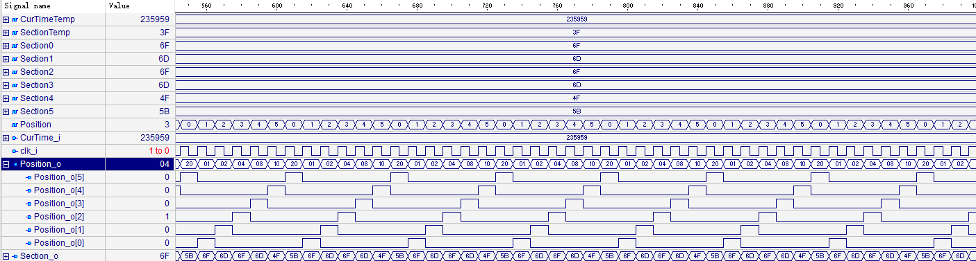
仿真结果如下
小时

分钟

秒钟

下图中输出CurrentTimeBCD_o旁边的数值105238表示带有时间信息的BCD码表示的时间10点52分38秒
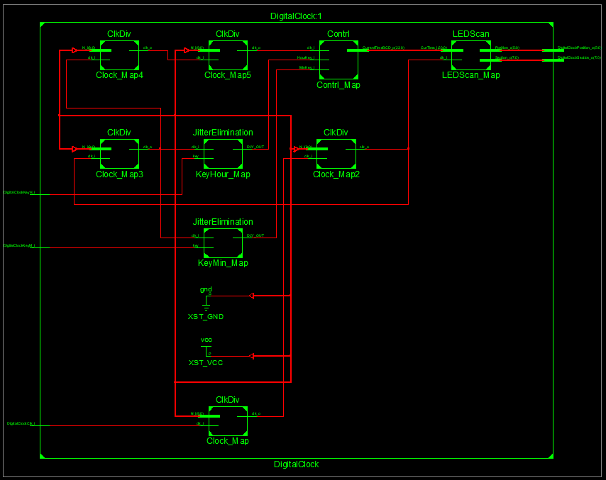
顶层模块
顶层模块就是把上面各个模块根据下图用线连接起来。下图为简洁只画了一个按键
稍微分析端口:
输入:按键1、按键2、时钟输入
输出:6位的位选信号、8位的段码信号
代码如下
library IEEE;
use IEEE.STD_LOGIC_1164.all;

entity DigitalClock is
	port(
		DigitalClockClk_i:IN STD_LOGIC;
		DigitalClockKeyM_i:IN STD_LOGIC;
		DigitalClockKeyH_i:IN STD_LOGIC;

		DigitalClockPosition_o:OUT STD_LOGIC_VECTOR(5 DOWNTO 0);
		DigitalClockSection_o: OUT STD_LOGIC_VECTOR(7 DOWNTO 0));

end DigitalClock;

architecture rtl of DigitalClock is

	component ClkDiv is
		port(
			clk_i:IN STD_LOGIC;
			N_i:  IN STD_LOGIC_VECTOR(9 DOWNTO 0);
			clk_o:OUT STD_LOGIC);
	end component;

	component JitterElimination is
		port(
			key: IN STD_LOGIC;
			clk_i:IN STD_LOGIC;
			DLY_OUT:OUT STD_LOGIC);

	end component;

	component LEDScan is
		port(
			CurTime_i:  IN STD_LOGIC_VECTOR(23 DOWNTO 0);
			clk_i:IN STD_LOGIC;
			Position_o:OUT STD_LOGIC_VECTOR(5 DOWNTO 0);
			Section_o: OUT STD_LOGIC_VECTOR(7 DOWNTO 0));
	end component;

	component Contrl is
		port(
			MinKey_i:IN STD_LOGIC;
			HourKey_i:IN STD_LOGIC;
			clk_i:IN STD_LOGIC;
			CurrentTimeBCD_o: OUT STD_LOGIC_VECTOR(23 downto 0));
	end component;
	signal N1: STD_LOGIC_VECTOR(9 DOWNTO 0):="0000100010";
	signal Clk1M: STD_LOGIC:='0';

	signal N2: STD_LOGIC_VECTOR(9 DOWNTO 0):="1111101000";
	signal Clk1k: STD_LOGIC:='0';

	signal N3: STD_LOGIC_VECTOR(9 DOWNTO 0):="0000001010";
	signal Clk100Hz: STD_LOGIC:='0';

	signal N4: STD_LOGIC_VECTOR(9 DOWNTO 0):="0000000010";
	signal Clk50Hz: STD_LOGIC:='0';

	signal N5: STD_LOGIC_VECTOR(9 DOWNTO 0):="0000110010";
	signal Clk1Hz: STD_LOGIC:='0';

	signal K1:STD_LOGIC:='1';--未按下
	signal K2:STD_LOGIC:='1';--未按下

	signal BCD:STD_LOGIC_VECTOR(23 downto 0):="000000000000000000000000";

begin

	Clock_Map: ClkDiv port map(
			clk_i=>DigitalClockClk_i,
			N_i=>N1,
			clk_o=>Clk1M);

	Clock_Map2: ClkDiv port map(
			clk_i=>Clk1M,
			N_i=>N2,
			clk_o=>Clk1k);

	Clock_Map3: ClkDiv port map(
			clk_i=>Clk1k,
			N_i=>N3,
			clk_o=>Clk100Hz);

	Clock_Map4: ClkDiv port map(
			clk_i=>Clk100Hz,
			N_i=>N4,
			clk_o=>Clk50Hz);

	Clock_Map5: ClkDiv port map(
			clk_i=>Clk50Hz,
			N_i=>N5,
			clk_o=>Clk1Hz);

	KeyMin_Map:JitterElimination port map(
			key=>DigitalClockKeyM_i,
			clk_i=>Clk100Hz,
			DLY_OUT=>K1);
	KeyHour_Map:JitterElimination port map(
			key=>DigitalClockKeyH_i,
			clk_i=>Clk100Hz,
			DLY_OUT=>K2);
	Contrl_Map: Contrl port map(
			MinKey_i=>K1,
			HourKey_i=>K2,
			clk_i=>Clk1Hz,
			CurrentTimeBCD_o=>BCD);

	LEDScan_Map: LEDScan port map(
			CurTime_i=>BCD,
			clk_i=>Clk1k,
			Position_o=>DigitalClockPosition_o,
			Section_o=>DigitalClockSection_o);

end rtl;
由于33.8688Mhz太大,软件仿真时间会比较慢,所以我没有把软件仿真图放出来。等过些时候到FPGA板子上验证
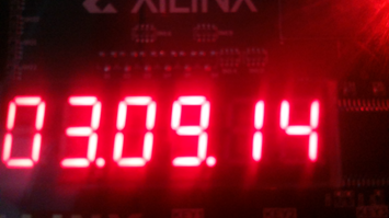
实验结果:符合设计预期结果,时分秒显示、按键都正常。
误差分析
由于1Mhz的时钟是由33.8688Mhz经过34分频生成的,所以每秒会有0.1078s的误差,也就是说1s过后此数字钟觉得时间过了1.1078s。分频方面我欠考虑了,如果想要提高精度要在分频方面思考。
生成原理图
尾声
新司机上路,各位系好安全带