网络拓扑图:

需求:通过在核心交换机上部署VRRP + MSTP技术,实现网关冗余,核心SW1作为vlan 10的主网关,SW 2作为vlan 20的网关
一、交换机配置VLNA和Trunk接口:
SW3配置:
<SW3>system-view
[SW3]undo info-center enable
[SW3]sysname SW3
[SW3]vlan batch 10 20
[SW3]interface gig0/0/3
[SW3-GigabitEthernet0/0/3]port link-type access
[SW3-GigabitEthernet0/0/3]port default vlan 10
[SW3-GigabitEthernet0/0/3]inter gig0/0/4
[SW3-GigabitEthernet0/0/4]port link-type access
[SW3-GigabitEthernet0/0/4]port default vlan 20
[SW3-GigabitEthernet0/0/4]quit

[SW3]port-group group-member gig0/0/1 to gig0/0/2        #加入端口组
[SW3-port-group]port link-type trunk     #端口类型为trunk
[SW3-port-group]port trunk allow-pass vlan all        #允许所有vlan通过
SW1:
<SW1>system-view
[SW1]undo info-center enable
[SW1]sysname SW1
[SW1]vlan batch 10 20 30
[SW1]port-group group-member gig0/0/1 to gig0/0/2        #加入端口组
[SW1-port-group]port link-type trunk        #更改端口类型为trunk
[SW1-port-group]port trunk allow-pass vlan all        #允许所有vlan通过
[SW1-port-group]quit

[SW1]interface GigabitEthernet 0/0/3        #进入G0/0/3接口
[SW1-GigabitEthernet0/0/3]port link-type access         #端口类型access
[SW1-GigabitEthernet0/0/3]port default vlan 30    #划分至vlan 30
[SW1-GigabitEthernet0/0/3]quit        #退出
SW2:
<SW2>system-view
[SW2]undo info-center enable
[SW2]sysname SW1
[SW2]vlan batch 10 20 30
[SW2]port-group group-member gig0/0/1 to gig0/0/2        #加入端口组
[SW2-port-group]port link-type trunk        #更改端口类型为trunk
[SW2-port-group]port trunk allow-pass vlan all        #允许所有vlan通过
[SW2-port-group]quit

[SW2]interface GigabitEthernet 0/0/3        #进入G0/0/3接口
[SW2-GigabitEthernet0/0/3]port link-type access         #端口类型access
[SW2-GigabitEthernet0/0/3]port default vlan 30    #划分至vlan 30
[SW2-GigabitEthernet0/0/3]quit        #退出
二、配置VRRP:
SW1:
[SW1]interface Vlanif 10        #进入vlanif10接口
[SW1-Vlanif10]ip address 192.168.10.254 24        #配置vlan 10接口地址
[SW1-Vlanif10]vrrp vrid 1 virtual-ip 192.168.10.1        #配置vlan 10的网关ip
[SW1-Vlanif10]vrrp vrid 1 priority 105         #将vlan 10网关的优先级设置为105,使SW 1成为vlan 10的主网关,优先级默认是100

[SW1-Vlanif10]vrrp vrid 1 track interface GigabitEthernet0/0/1 reduced 80        # #追踪G0/0/1接口,如果端口发生故障,将VRRP优先级减80
[SW1-Vlanif10]vrrp vrid 1 track interface GigabitEthernet0/0/2 reduced 80
[SW1-Vlanif10]vrrp vrid 1 track interface GigabitEthernet0/0/3 reduced 80
[SW1-Vlanif10]quit


[SW1]interface vlanif 20        #进入vlanif 20接口
[SW1-Vlanif20]ip address 192.168.20.254 24        #配置vlan 20接口地址
[SW1-Vlanif20]vrrp vrid 2 virtual-ip 192.168.20.1        #配置vlan 20的网关ip

[SW1-Vlanif20]vrrp vrid 2 track interface GigabitEthernet 0/0/1 reduced 90        #追踪G0/0/1接口,如果端口发生故障,将VRRP优先级减90
[SW1-Vlanif20]vrrp vrid 2 track interface GigabitEthernet 0/0/2 reduced 90
[SW1-Vlanif20]vrrp vrid 2 track interface GigabitEthernet 0/0/3 reduced 90
SW2:
[SW2]interface Vlanif 10        #进入vlanif10接口
[SW2-Vlanif10]ip address 192.168.10.253 24        #配置vlan 10接口地址
[SW2-Vlanif10]vrrp vrid 1 virtual-ip 192.168.10.1        #配置vlan 10的网关ip

[SW2-Vlanif10]vrrp vrid 1 track interface GigabitEthernet0/0/1 reduced 80        #追踪G0/0/1接口,如果发生故障,将VRRP优先级减80
[SW2-Vlanif10]vrrp vrid 1 track interface GigabitEthernet0/0/2 reduced 80
[SW2-Vlanif10]vrrp vrid 1 track interface GigabitEthernet0/0/3 reduced 80
[SW2-Vlanif10]quit


[SW2]interface vlanif 20        #进入vlanif 20接口
[SW2-Vlanif20]ip address 192.168.20.253 24        #配置vlan 20接口地址
[SW2-Vlanif20]vrrp vrid 2 virtual-ip 192.168.20.1        #配置vlan 20的网关ip
[SW2-Vlanif20]vrrp vrid 2 priority 108        #将vlan 20网关优先级设置为108,使SW 2成为vlan 20的主网关

[SW2-Vlanif20]vrrp vrid 2 track interface GigabitEthernet0/0/1 reduced 90        #追踪G0/0/1接口,如果发生故障,将VRRP优先级减90
[SW2-Vlanif20]vrrp vrid 2 track interface GigabitEthernet0/0/2 reduced 90
[SW2-Vlanif20]vrrp vrid 2 track interface GigabitEthernet0/0/3 reduced 90
[SW2-Vlanif20]quit        #退出
配置完VRRP后,我们再分别使用PC去ping各自的网关地址,如下:
三、配置MSTP:
SW1、SW2、SW3都需配置:
[SW1]stp region-configuration         #STP区域设置
[SW1-mst-region]region-name kang        #创建区域名kang
[SW1-mst-region]instance 1 vlan 10        #创建实例1并绑定vlan 10
[SW1-mst-region]instance 2 vlan 20        #创建实例2并绑定vlan 20
[SW1-mst-region]active region-configuration        #激活配置
上面配置完成后,默认所有vlan都在MSTP的实例0中,还需要更改MSTP实例的优先级:
SW1:
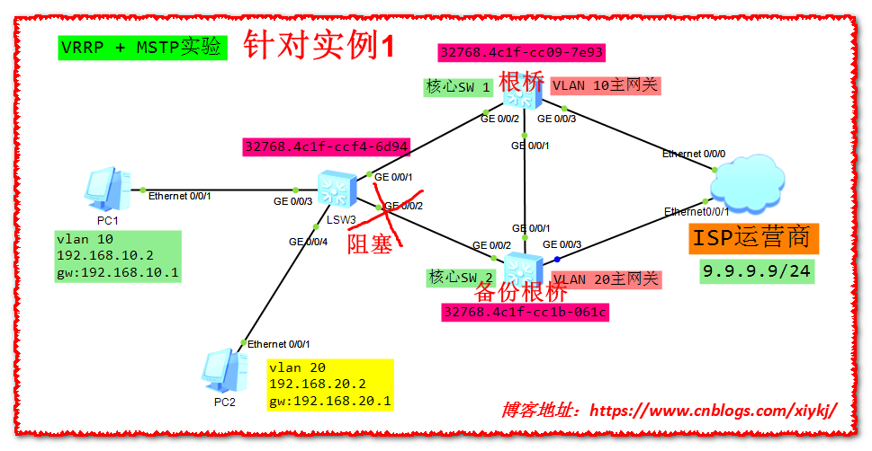
[SW1]stp instance 1 root primary         #针对实例1将SW 1设置为根桥
[SW1]stp instance 2 root secondary        #针对实例2将SW 1设置为备份根桥
针对实例1将堵塞SW3的G0/0/2端口
SW2:
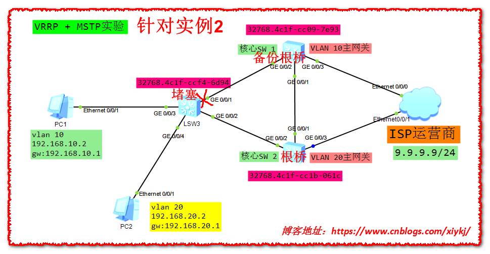
[SW2]stp instance 2 root primary         #针对实例2将SW 2设置为根桥
[SW2]stp instance 1 root secondary        #针对实例1将SW 2设置为备份根桥
针对实例2将堵塞SW3的G0/0/1端口