-
DT.IMG布局
|
hdr |
zImage |
Ramdisk.img |
DT.img |
其中DT.img由DTBTOOL打包所有编译生成的dtb生成;布局如下:
|
DT header |
dt_entry_0 |
dt_entry_1 |
dt_entry_2 |
…… |
其中dt_entry_x对应是某棵DeviceTree编译输出的***.dtb。
-
Bootloader 加载DviceTree
函数 int boot_linux_from_mmc(void);
Bootloader
正常启动时把zImage、ramdisk.img以及某个dt_entry_x(dt.img中包含多个条目)分别从存储器(这里以eMMC为例)中读取到RAM中的具体位置。
具体加载哪个dt_entry_x,有bootloader根据基板信息(platform_id/target_id/soc_version)等按照某个策略找到最匹配的。
-
调用boot_linux();
-
|
boot_linux((void *)hdr->kernel_addr, (void *)hdr->tags_addr, (const char *)hdr->cmdline, board_machtype(), (void *)hdr->ramdisk_addr, hdr->ramdisk_size); |
|
其中参数: kernel_addr : 是zImage在RAM中的地址; tags_addr : 是dt_entry在RAM中的地址; cmdline : 是编译zImage时打包进去的,; 如下: [mkbooting —kernel$KERNEL ramdisk ./booting/ramdisk $BOARD_CFG.img —cmdline "console=ttyHSL0,115200,n8, androidboot.console=ttyHSL0 androidboot.hardware=qcom user_debug=31 msm_rtb.filter=0x37" --base 0x0000 0000—pagesize2048—ramdisk_offset 0x0200 0000 --tags_offset 0x01E0 0000 –dt ./booting/dt_$BOARD_CFG.img –output $BOOTIMG] machtype 目前在高通平台没有使用 ramdisk 是ramdisk在RAM中的地址 ramdisk_size 是ramdisk的大小 |
-
调用update_device_tree();函数把commandline/ramdisk/ramdisk_size等信息更新到devicetree中的对应节点中。
|
update_device_tree( (void *)tags, (const char *)final_cmdline, ramdisk, ramdisk_size ); |
|
/chosen/bootargs ßfinal_cmdline /chosen/linux,initrd-start ßramdisk /chosen/linux,initrd-end ßramdisk+ramdisk_size 注释:这里的final_cmdline,有boot_linux中的cmdline和lk动态配置的commandline组合而成; 比如说pwr_reason¥lcd信息等。 |
-
调用entry(0, machtype, (unsigned*)tags_phys);启动内核!
向内核传递的信息只有machtype和(unsigned*)tags_phys;其中machtype为零、tags_phys为对应的devicetree(dtb)在RAM中的地址。
-
Kernel展开DTB
-
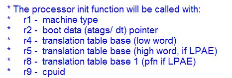
内核通过DeviceTree识别特定的machine(DT_MACHINE_START)
Kernel的函数在Head.S中的ENTRY(stext),此时的寄存器r1,r2分别存储着machtype和devicetree(dtb)的地址;
-
|
|
-
并调用kernel如下
|
str r1,[r5] @Save machine type str r2,[r6] @Save atags pointer b start_kernel |
|
此时r1,r2的值存储到r[5],r[6];也就是_machine_arch_type、_atags_pointer中,以便在C代码空间访问。 |
-
进入main.c中的start_kernel()函数,调用setup_arch()函数
|
|

进入setup.c中的setup_arch()函数,调用setup_machine_fdt()函数
|
|
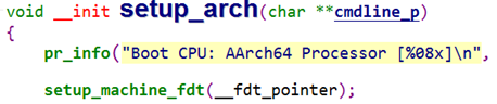
进入devtree.c中的setup_machine_fdt()函数,在mdesc(即machine_desc)的table中搜索与DT数据最匹配的machine。设备树根节点的compatible属性跟mdesc的table数组相比较决定最匹配的machine。找到最匹配的machine后,setup_machine_fdt()返回machine_desc数组的基地址,否则返回null。
|
/** * setup_machine_fdt - Machine setup when an dtb was passed to the kernel * @dt_phys: physical address of dt blob * If a dtb was passed to the kernel in r2, then use it to choose the * correct machine_desc and to setup the system. */ const struct machine_desc * __init setup_machine_fdt(unsigned int dt_phys) { const struct machine_desc *mdesc, *mdesc_best = NULL; #ifdef CONIG_FARCH_MULTIPLATFORM DT_MACHINE_START(GENERIC_DT, "Generic DT based system") MACHINE_END mdesc_best = &__mach_desc_GENERIC_DT; #endif if (!dt_phys || !early_init_dt_verify(phys_to_virt(dt_phys))) return NULL; mdesc = of_flat_dt_match_machine(mdesc_best, arch_get_next_mach); if (!mdesc) { const char *prop; int size; unsigned long dt_root; early_print(" Error: unrecognized/unsupported " "device tree compatible list: [ "); dt_root = of_get_flat_dt_root(); prop = of_get_flat_dt_prop(dt_root, "compatible", &size); while (size > 0) { early_print("'%s' ", prop); size -= strlen(prop) + 1; prop += strlen(prop) + 1; } early_print("] "); dump_machine_table(); /* does not return */ } /* We really don't want to do this, but sometimes firmware provides buggy data */ if (mdesc->dt_fixup) mdesc->dt_fixup(); early_init_dt_scan_nodes(); /* Change machine number to match the mdesc we're using */ __machine_arch_type = mdesc->nr; return mdesc; } |
-
设备加载流程
上述3得到基地址后会初始化板级信息
|
以msm8953为例: #include <linux/kernel.h> #include <asm/mach/arch.h> #include "board-dt.h"
static const char *msm8953_dt_match[] __initconst = { "qcom,msm8953", "qcom,apq8053", NULL }; static void __init msm8953_init(void) { board_dt_populate(NULL); } DT_MACHINE_START(MSM8953_DT, "Qualcomm Technologies, Inc. MSM 8953 (Flattened Device Tree)") .init_machine = msm8953_init, .dt_compat = msm8953_dt_match, MACHINE_END |
-
在start_kernel()开启新的线程kernel_init(),并根据devicetree创建设备。
start_kernel(void)—>kernel_init(void *unused)—>kernel_init_freeable()—>do_basic_setup()—>do_initcalls();do_initcalls()完成各个等级的初始化工作,涉及devicetree初始化工作如下:
|
static int __init customize_machine(void) { of_clk_init(NULL); /* * Traverses flattened DeviceTree - registering platform devices * (if any) complete with their resources */ of_platform_populate(NULL, of_default_bus_match_table, NULL, NULL); if (machine_desc->init_machine) machine_desc->init_machine(); return 0; } arch_initcall(customize_machine); |
也就是回调具体的DT_MACHINE中的 init_machine,以msm8953为例就是 msm8953_init。
|
msm8953_init()函数: static void __init msm8953_init(void) { board_dt_populate(NULL); } |
|
void __init board_dt_populate(struct of_dev_auxdata *adata) { of_platform_populate(NULL, of_default_bus_match_table, NULL, NULL);
/* Explicitly parent the /soc devices to the root node to preserve * the kernel ABI (sysfs structure, etc) until userspace is updated */ of_platform_populate(of_find_node_by_path("/soc"), of_default_bus_match_table, adata, NULL); } |
|
of_platform_populate 递归完成device的创建工作。 |
在linux设备模型里, 假设它的所有设备是连接在bus controller上的子设备.e.g. i2c_client 是i2c_master的子设备;唯一没有特定父设备类型的模型就是platform_device.
调用of_platform_populate(NULL, of_default_bus_match_table, NULL, NULL)完成根设备节点创建。调用of_platform_populate(of_find_node_by_path("/soc"),of_default_bus_match_table, adata, NULL);完成/soc下相关节点设备的创建。
-
Linux下的i2c驱动
-
设备模型
由总线(bus_type)+设备(device)+驱动(device_driver)组成,在该模型下,所有的设备通过总线连接起来,即使有些设备没有连接到一根物理总线上,linux为其设置了一个内部的、虚拟的platform总线,用以维持
总线、驱动、设备的关系。
对于实现一个Linux下的设备驱动,可以分为两大步:
-
设备注册
-
驱动注册
当然还有一些细节问题:
-
驱动的probe函数
-
驱动和设备是怎么绑定的
-
-
i2c设备驱动的几个数据结构
-
i2c_adapter:
每一个i2c_adapter对应一个物理上的i2c控制器,在i2c总线驱动probe函数中动态创建。通过i2c_adapter注册到i2c_core。
-
-
|
/* * i2c_adapter is the structure used to identify a physical i2c bus along * with the access algorithms necessary to access it. */ struct i2c_adapter { struct module *owner; unsigned int class; /* classes to allow probing for */ const struct i2c_algorithm *algo; /* the algorithm to access the bus */ void *algo_data;
/* data fields that are valid for all devices */ struct rt_mutex bus_lock;
int timeout; /* in jiffies */ int retries; struct device dev; /* the adapter device */
int nr; char name[48]; struct completion dev_released;
struct mutex userspace_clients_lock; struct list_head userspace_clients;
struct i2c_bus_recovery_info *bus_recovery_info; }; |
-
i2c_algorithm:
i2c_algorithm中的关键函数master_xfer(),以i2c_msg为单位产生i2c访问需要的信号,不同平台所对应的master_xfer()是不同的,需要根据所用平台的硬件特性实现自己的xxx_xfer()方法以填充i2c_algorithm的master_xfer指针;
|
/** * struct i2c_algorithm - represent I2C transfer method * @master_xfer: Issue a set of i2c transactions to the given I2C adapter * defined by the msgs array, with num messages available to transfer via * the adapter specified by adap. * @smbus_xfer: Issue smbus transactions to the given I2C adapter. If this * is not present, then the bus layer will try and convert the SMBus calls * into I2C transfers instead. * @functionality: Return the flags that this algorithm/adapter pair supports * from the I2C_FUNC_* flags. * * The following structs are for those who like to implement new bus drivers: * i2c_algorithm is the interface to a class of hardware solutions which can * be addressed using the same bus algorithms - i.e. bit-banging or the PCF8584 * to name two of the most common. * * The return codes from the @master_xfer field should indicate the type of * error code that occured during the transfer, as documented in the kernel * Documentation file Documentation/i2c/fault-codes. */ struct i2c_algorithm { /* If an adapter algorithm can't do I2C-level access, set master_xfer to NULL. If an adapter algorithm can do SMBus access, set smbus_xfer. If set to NULL, the SMBus protocol is simulated using common I2C messages */ /* master_xfer should return the number of messages successfully processed, or a negative value on error */ int (*master_xfer)(struct i2c_adapter *adap, struct i2c_msg *msgs, int num); int (*smbus_xfer) (struct i2c_adapter *adap, u16 addr, unsigned short flags, char read_write, u8 command, int size, union i2c_smbus_data *data) /* To determine what the adapter supports */ u32 (*functionality) (struct i2c_adapter *); }; |
-
i2c_client:
代表一个挂载到i2c总线上的i2c从设备,包含该设备所需要的数据:
该i2c从设备所依附的i2c控制器:strut i2c_adapter *adapter
该i2c从设备的驱动程序:struct i2c_driver *driver
该i2c从设备的访问地址addr
该i2c从设备的名称name
|
/** * struct i2c_client - represent an I2C slave device * @flags: I2C_CLIENT_TEN indicates the device uses a ten bit chip address; * I2C_CLIENT_PEC indicates it uses SMBus Packet Error Checking * @addr: Address used on the I2C bus connected to the parent adapter. * @name: Indicates the type of the device, usually a chip name that's * generic enough to hide second-sourcing and compatible revisions. * @adapter: manages the bus segment hosting this I2C device * @dev: Driver model device node for the slave. * @irq: indicates the IRQ generated by this device (if any) * @detected: member of an i2c_driver.clients list or i2c-core's * userspace_devices list * * An i2c_client identifies a single device (i.e. chip) connected to an * i2c bus. The behaviour exposed to Linux is defined by the driver * managing the device. */ struct i2c_client { unsigned short flags; /* div., see below */ unsigned short addr; /* chip address - NOTE: 7bit */ /* addresses are stored in the */ /* _LOWER_ 7 bits */ char name[I2C_NAME_SIZE]; struct i2c_adapter *adapter; /* the adapter we sit on */ struct device dev; /* the device structure */ int irq; /* irq issued by device */ struct list_head detected; }; |
-
i2c总线驱动
-
功能划分
从硬件功能上可划分为:i2c控制器和i2c外设(从设备)。每个i2c控制器总线上都可以挂载多个i2c外设。Linux中对i2c控制器和外设分开管理:通过i2c-msm-qup.c文件完成i2c控制器的设备注册和驱动注册;通过i2c-core.c为具体的i2c外设提供了统一的设备注册接口和驱动注册接口,它分离了设备驱动和硬件控制的实现细节。
需要注意的是:设备与驱动的对应关系是多对一的;即如果设备类型是一样的,会共用同一套驱动。
-
设备注册
将i2c控制器设备注册为platform设备,为每一个控制器定义一个struct platform_device数据结构,并且把.name都设置为"i2c_qup"。后面会通过名字进行匹配驱动的。然后是调用platform_device_register()函数,将设备注册到platform bus上。
-
|
static struct of_device_id i2c_qup_dt_match[] = { { .compatible = "qcom,i2c-qup", }, {} };
static struct platform_driver qup_i2c_driver = { .probe = qup_i2c_probe, .remove = qup_i2c_remove, .driver = { .name = "i2c_qup", .owner = THIS_MODULE, .pm = &i2c_qup_dev_pm_ops, .of_match_table = i2c_qup_dt_match, }, }; |
设备注册完成后其直观的表现就是在文件系统下出现:sys/bus/platform/devices/xxx.o
通过platform_device_register()函数进行注册的过程,就是对platform_device这个数据结构的更改,逐步完成.dev.parent/.dev.kobj/.dev.bus的赋值,然后将.dev.kobj加入到platform_busàkobj的链表上。
-
驱动注册步骤和设备注册类似,也是为驱动定义了一个数据结构:
|
static struct of_device_id i2c_qup_dt_match[] = { { .compatible = "qcom,i2c-qup", }, {} };
static struct platform_driver qup_i2c_driver = { .probe = qup_i2c_probe, .remove = qup_i2c_remove, .driver = { .name = "i2c_qup", .owner = THIS_MODULE, .pm = &i2c_qup_dev_pm_ops, .of_match_table = i2c_qup_dt_match, }, };
/* QUP may be needed to bring up other drivers */ int __init qup_i2c_init_driver(void) { static bool initialized;
if (initialized) return 0; else initialized = true;
return platform_driver_register(&qup_i2c_driver); } EXPORT_SYMBOL(qup_i2c_init_driver); arch_initcall(qup_i2c_init_driver);
static void __exit qup_i2c_exit_driver(void) { platform_driver_unregister(&qup_i2c_driver); } module_exit(qup_i2c_exit_driver); |
-
设备与驱动匹配
match过程:
i2c_core.c:i2c_add_driver()—>i2c_register_driver()—>i2c_bus_type—>i2c_device_match()—>of_driver_match_device(),用驱动的信息与device的node处匹配,如果相同,则匹配,匹配上之后运行driver_register调用
driver_probe_device(dd.c中)进行设备与驱动的绑定。
-
probe绑定过程
初始化.probe和.remove函数,然后调用i2c_add_driver进行注册,主要调用函数流程:
i2c_add_driver—>i2c_register_driver—>bus_add_driver—>driver_attach—>driver_probe_device—>really_probe(里面讲设备的驱动指针指向驱动,如果匹配成功,执行dev—>bus—>probe即设备驱动里的probe函数)—>driver_bound(绑定)
需要注意的是driver_attach,这个函数遍历了总线上(platform_bus_type)的所有设备,寻找与驱动匹配的设备,并把满足条件的设备结构体上的驱动指针指向驱动,从而完成了驱动和设备的匹配(_driver_attach函数完成)
如果匹配到设备,这是就需要执行platform_bus_type的probe函数,最终会调用驱动的probe函数。