Introduction
The performance of the RI estimation is defined in TS36.101 Section 9.5.1.1 is as follows:
-
the ratio of the throughput obtained when transmitting based on UE reported RI and that obtained when transmitting with fixed rank 2 shall be >= 1 (Test 1)
-
the ratio of the throughput obtained when transmitting based on UE reported RI and that obtained when transmitting with fixed rank 1 shall be >= 1.05 (Test 2)
This example tests that these requirements are met.
Simulation Configuration
The example is executed for a simulation length of 10 frames at an SNR of 0.0dB. The fixed RI value is configured to be 2, therefore simulating TS36.101 Section 9.5.1.1 Test 1. A large number of NFrames should be used to produce meaningful results. The variable FixedRI controls which of the performance requirements described in the introduction are tested: FixedRI=2 corresponds to Test 1 and FixedRI=1 corresponds to Test 2. Note that a target SNR of 20.0dB rather than 0.0dB applies for Test 2.
NFrames = 10;
SNRdB = 0.0;
FixedRI = 2;
Channel Estimator Configuration
The channel estimator is configured with a structure cec. The variable perfectChanEstimator controls channel estimator behavior. Valid values are true or false. When set to true a perfect channel estimator is used otherwise an imperfect estimate of the channel is used, based on the values of received pilot signals. In this example, we enable the perfect channel estimator.
% Configure channel estimator
cec.PilotAverage = 'UserDefined';   % Type of pilot symbol averaging
cec.FreqWindow = 9;                 % Frequency window size in REs
cec.TimeWindow = 9;                 % Time window size in REs
cec.InterpType = 'Cubic';           % 2D interpolation type
cec.InterpWindow = 'Centered';      % Interpolation window type
cec.InterpWinSize = 1;              % Interpolation window size

% Channel estimator behavior
perfectChanEstimator = true;
Set RI and CQI/PMI Delays
Initialize RI and CQI/PMI reporting delays in subframes; the RI delay is 9 subframes rather than 8 subframes in accordance with Note 5 of TS36.101 Table 9.5.1.1-1. Note that the feedback of the RI, CQI and PMI is assumed to be perfect, with the values being fed back in buffers rather than being fed back in an uplink transmissions.
riDelay = 9;     % subframes
cqipmiDelay = 8; % subframes
Codebook Subset Restriction Bitmaps
In order to control the PMI selection which underlies the rank selection, codebook subset restriction bitmaps are used as described in TS36.213 Section 7.2. codebookSubsetRI1 configures the codebook subset restriction to the two precoders for rank 1, used for FixedRI=1. codebookSubsetRI2 configures the codebook subset restriction to the single precoder of rank 2, used for FixedRI=2. codebookSubsetUEReported is the union of these codebook subset restrictions and allows the rank to be selected dynamically in the case of UE reported RI.
codebookSubsetRI1 = '000011';
codebookSubsetRI2 = '010000';
codebookSubsetUEReported = '010011';
ystem Processing
The main processing is split into two phases, configured via the riConfig loop variable. These phases implement the two measurements required in the performance test defined in TS36.101 Section 9.5.1.1 :
-
Fixed RI. The first phase (
riConfig=1) performs PDSCH transmission and reception where the rank is set to a fixed value (either 1 or 2, selected by the variableFixedRIabove). The final throughput is recorded.
-
UE reported RI. In the second phase (
riConfig=2), the number of transmission layers is selected on the basis of UE reported RI, with the RI being updated every 5 subframes. The final throughput is recorded. The throughput ratio (measuredGamma) between the fixed RI phase and the UE reported phase is calculated and checked against the specified performance requirement.
The processing is performed on a subframe by subframe basis using the following steps:
-
Select RI. The current RI is read from the oldest value in the RI buffer
riBuffer. The current RI is used to configure the number of transmission layers and codewords for the PDSCH.
-
Select CQI/PMI. The current CQI and PMI are read from the oldest values in the CQI and PMI buffers
cqiBufferandpmiBuffer. The current PMI is used to configure the precoding for the PDSCH. Note that for RI=2, there are two CQI values, one for each codeword; for RI=1 there is one CQI value for the single codeword.
-
Select MCS according to CQI. The Modulation and Coding Scheme (MCS) index corresponding to the CQI is selected for each codeword by means of a lookup table defined in TS36.101 Table A.4-1 CSI RMC RC.2 FDD (MCS.2).
-
Determine Transport Block Size and modulation order. The MCS index for each codeword is passed to the lteMCS function which calculates the corresponding Transport Block Size (TBS) index and modulation order; the lteTBS function is then used to calculate the TBS for each codeword from the TBS index and the number of resource blocks allocated to the PDSCH.
-
Transmit and receive waveform. Transport block data is generated for one or two codewords as appropriate and passed to lteRMCDLTool to create a transmitted downlink waveform. This waveform is then passed through a fading channel and AWGN noise is added. The received signal is synchronized and OFDM demodulated and channel estimation is performed.
-
Measure PDSCH throughput. The PDSCH and DL-SCH are decoded and the CRC pass/fail for each codeword is recorded to determine the data throughput.
-
Update RI. If an RI update is scheduled in this subframe, use the channel estimate to update the RI with the lteRISelect function. The updated RI value is recorded in the RI buffer. The codebook subset restriction bitmap ensures that the reported RI will remain fixed for the fixed RI phase but will be dynamically selected for the UE reported RI phase. If an RI update is not scheduled in this subframe, the previous RI value is reused.
-
Update CQI/PMI. If a CQI/PMI update is scheduled in this subframe, use the channel estimate to update the CQI and PMI with the lteCQISelect and ltePMISelect functions. The updated CQI and PMI values are recorded in the CQI and PMI buffers. If a CQI/PMI update is not scheduled in this subframe, the previous CQI and PMI values are reused.
Plot Results
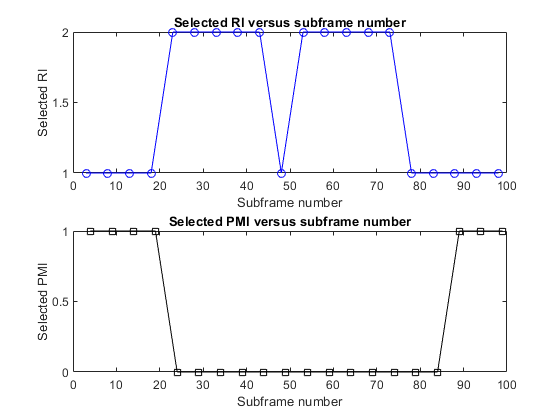
Two figures are produced. The first figure has two subplots: the first subplot shows the reported RI for each subframe; the second subplot shows the reported PMI for each subframe. The second figure also has two subplots: the first subplot shows the estimated SINR for each subframe; the second subplot shows the reported CQI for each subframe. These plots illustrate how the RI, PMI and CQI vary over time due to the fading channel.

Reference,
1. TS 36.101
2. MathWorks